
.035 Welding Wire Is a Diameter, Not a Complete Selection
Choose and set up .035 welding wire by process, classification, polarity, gas, feeder parts and the machine or wire manufacturer’s parameter chart.
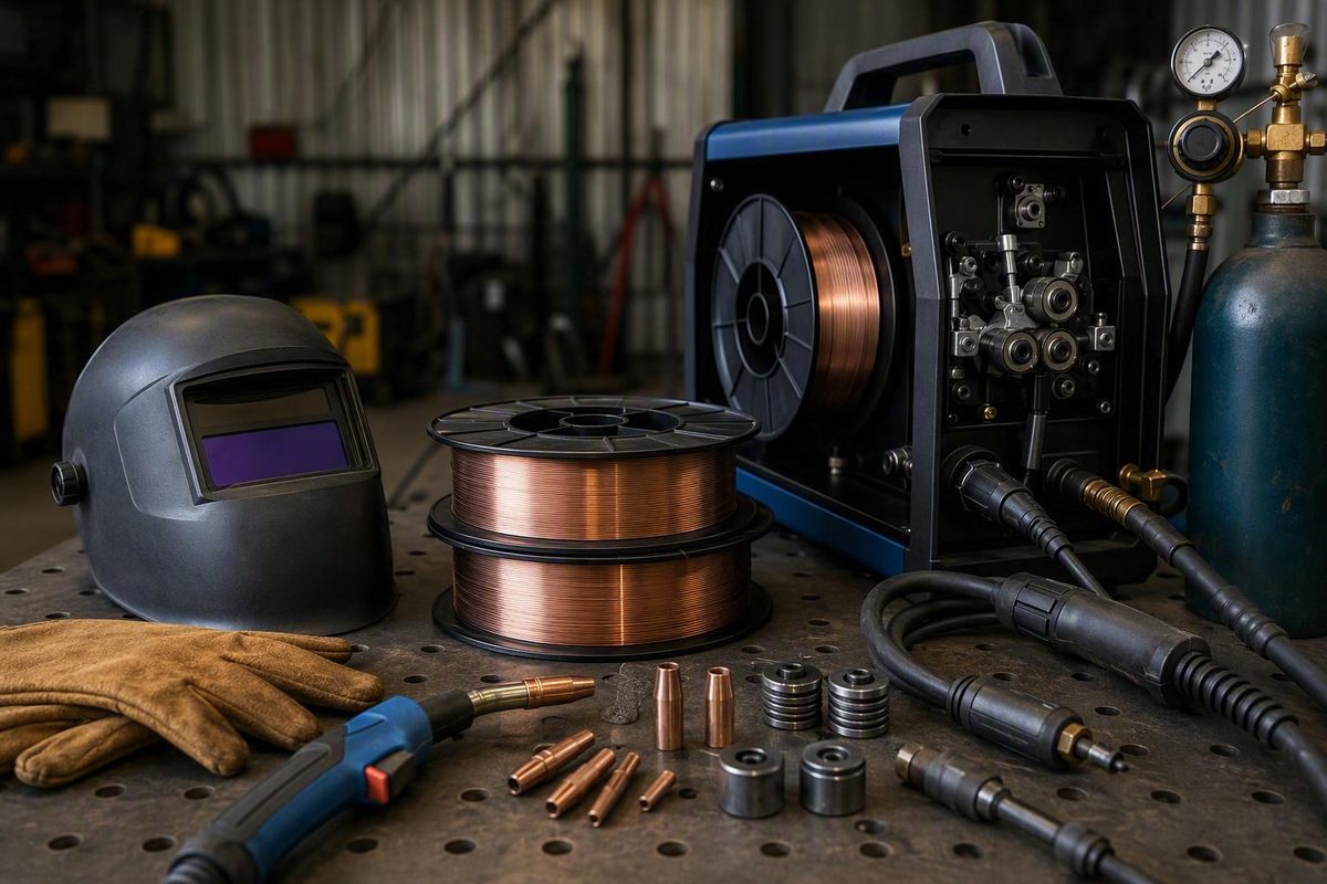
.035 welding wire is 0.035 inch (0.9 mm) in diameter. That dimension alone does not tell you whether the wire is solid, metal-cored, gas-shielded flux-cored or self-shielded flux-cored—or whether it suits the base metal and required weld.
For ordinary carbon-steel work, the common choice is often either .035 ER70S-6 solid wire with shielding gas or .035 E71T-11 self-shielded flux-cored wire. They are not interchangeable setups.
| .035-inch example | Process | External gas | Published polarity |
|---|---|---|---|
| ER70S-6 solid wire | GMAW/MIG | Yes | DCEP (DC+) |
| E71T-11 self-shielded wire | FCAW-S | No | DCEN (DC−) for the cited NR-211-MP product |
Lincoln’s ER70S-6 SuperArc L-56 data lists .035-inch packages, DC+ polarity and several compatible shielding gases, including 100% CO2 and argon/CO2 blends. It also supports short-circuit, globular, axial-spray and pulsed-spray transfer modes (Lincoln Electric). By contrast, Lincoln’s .035-inch NR-211-MP is an E71T-11 self-shielded flux-cored wire with published DC− operating data (Lincoln Electric). Always follow the label and datasheet for the exact wire rather than applying either example to every .035 product.
When .035 wire makes sense
For solid steel wire, Miller gives .035 inch a general working range of 50–180 amps. Its neighboring guidance lists .030 inch at 40–145 amps and .045 inch at 75–250 amps (Miller Electric). This makes .035 a useful middle diameter when a machine’s output, feeder and gun all support it.
That range is a selection guide, not a universal setting. A specific Lincoln ER70S-6 datasheet, for example, publishes these .035-inch procedure points:
- Short-circuit with 100% CO2: 100–250 inches per minute (ipm), 18–22 volts and approximately 80–175 amps.
- Spray transfer with 90% argon/10% CO2: 375–600 ipm, 23–30 volts and approximately 195–275 amps.
Those values belong to that wire, gas, polarity, transfer mode and listed contact-tip-to-work distance—not every spool marked .035. Use your machine’s door chart or manual first, then the exact wire datasheet. For a broader diameter comparison, see the solid MIG welding wire size chart.
Do not select .035 solely from plate thickness. Joint design, root opening, position, travel speed, transfer mode, available amperage and required deposition rate all affect the decision. Very thin sheet may be easier to control with a smaller solid wire, while a low-output machine may not reach the operating range needed for a particular joint.
Set up the machine before changing settings
Work through these checks in order:
- Identify the complete wire. Record classification, alloy, solid or cored construction, diameter and manufacturer—not just “.035.” If choosing carbon-steel solid wire, this MIG solid-wire guide explains the additional machine and spool checks.
- Confirm the power source range. Make sure the welder can deliver the voltage, amperage and wire-feed speed specified for the intended joint and transfer mode.
- Fit the feed path. Use a drive-roll groove, inlet guide, liner and .035 contact tip approved for 0.035-inch wire. Verify the spool physically fits the hub.
- Set polarity from the wire documentation. The examples above demonstrate why “MIG polarity” is not enough: the solid ER70S-6 example uses DC+, while the self-shielded E71T-11 example uses DC−.
- Connect the specified gas, if required. Solid wire needs its documented external shielding gas. Self-shielded wire does not become solid-wire MIG merely because both products have the same diameter.
- Start from the machine chart or wire datasheet. Match material, thickness, joint, position, gas and transfer mode. Run a representative coupon before welding the part.
For one product-specific FCAW-S example, Lincoln publishes .035 NR-211-MP settings from 50 to 275 ipm, 14–21 volts and approximately 30–155 amps, with a 1/2- to 5/8-inch contact-tip-to-work distance. The same datasheet limits that product’s maximum plate thickness to 5/16 inch (Lincoln Electric). That limit and those settings must not be generalized to other E71T-11 wires or to gas-shielded flux core.
Diagnose the symptom instead of chasing one knob
Wire stubs into the work: Check whether voltage is too low for the selected wire-feed speed, but first verify polarity, work-cable contact and unobstructed feeding. Miller advises increasing voltage when the arc stubs into the workpiece (Miller Electric).
Wire burns back to the tip: Check for erratic feeding, excessive voltage relative to wire-feed speed, an oversized or worn tip, liner restrictions and inconsistent gun position. Miller’s guidance says to reduce voltage when the arc is erratic and burns at the tip (Miller Electric).
Porosity with solid wire: Confirm gas is on, flow is appropriate, the nozzle and diffuser are clear, hoses and fittings do not leak, and drafts are not stripping the shield. Also remove oil, paint, rust and moisture from the joint area.
Birdnesting or surging: With power isolated according to the manual, inspect the spool brake, drive-roll groove and pressure, inlet alignment, liner, contact tip and gun-cable bends. Increasing drive pressure can hide rather than solve a restriction.
A stable-looking bead is not proof of penetration, fusion or acceptance. Critical or code work requires the specified filler, qualified procedure and required inspection or testing. Lincoln’s NR-211-MP sheet explicitly warns that test results should not be treated as expected results in a particular weldment and tells users to confirm suitability through qualification testing or other appropriate means (Lincoln Electric).
Do not overlook fume control
Wire choice changes the process, but it does not remove welding hazards. OSHA says exposure depends partly on the welding process, base and filler metals, location, work practices, air movement and ventilation controls. It recommends keeping local-exhaust capture close to the plume source and notes that respiratory protection may be required when work practices and ventilation do not reduce exposure to safe levels (OSHA). Use the required helmet shade, safety glasses, flame-resistant protection and gloves, and follow the machine manual and site hot-work rules.