
Choose the Right Solid Wire for the Metal, Machine, and Job
Even when a machine accepts.035-inch wire, it may not hold the spool, feed the alloy reliably or provide the output the joint requires.
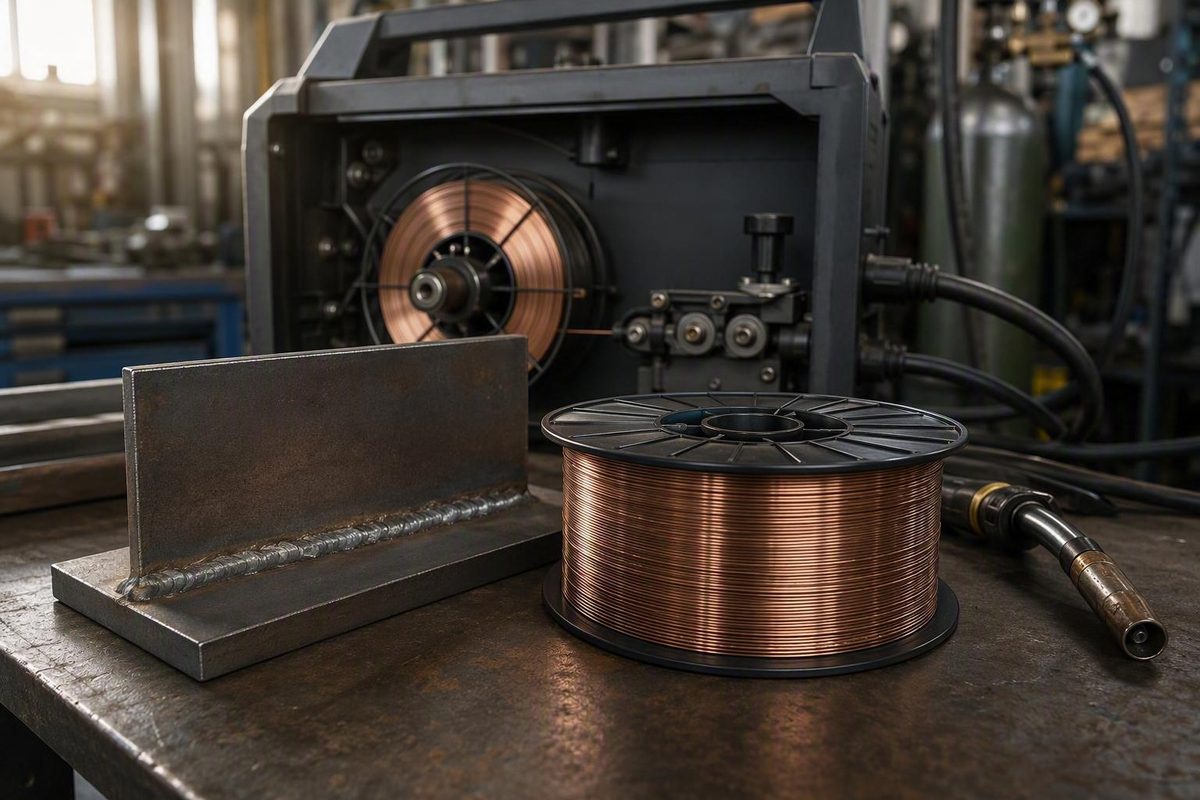
Buying MIG solid welding wire is not simply a matter of choosing a familiar classification or the largest spool that fits the budget. The wire, base metal, shielding gas, polarity, power source, gun, feeder, welding position, and work environment form one system. A mismatch can cause poor feeding, an unstable arc, porosity, burn-through, lack of fusion, or avoidable rework.
Use this selection order:
- Identify the base metal and required weld properties.
- Assess surface condition, material thickness, and joint design.
- Consider welding position and environmental conditions.
- Confirm the machine’s output and supported operating modes.
- Select a broad wire-diameter category.
- Verify shielding gas and polarity.
- Audit the complete feed path and spool fit.
- Choose a package size that matches consumption and storage conditions.
For a quick buying decision, use this summary:
| Job context | Likely starting point | Verify before buying |
|---|---|---|
| Thin, clean indoor carbon-steel sheet | Smaller-diameter ER70S solid wire | Exact classification, low-end machine control, gas, polarity, fit-up |
| General indoor mild-steel fabrication | ER70S-3 or ER70S-6 in a machine-supported diameter | Surface condition, required properties, joint design, feeder components |
| Stainless steel | Stainless filler matched to the identified alloy | Base alloy, service requirements, procedure, shielding gas |
| Aluminum | Aluminum filler matched to the identified alloy | Feed system, gun arrangement, gas, liner and drive components |
| Windy field repair | Consider suitable self-shielded flux-cored wire | Classification, polarity, position rating, base-metal compatibility |
| Higher-deposition production work | Evaluate larger solid wire, gas-shielded flux core, or metal core | Machine output, duty cycle, transfer mode, procedure, total job cost |
This is a screening guide, not a universal procedure. Product documentation, equipment manuals, applicable procedures, and site requirements control the final setup.
What solid MIG welding wire is—and what it needs to work
Solid MIG wire is a continuous consumable electrode. A feeder pushes it from a spool through the gun and contact tip. At the workpiece, the wire establishes the arc, melts, and becomes deposited filler metal in the joint.
The word solid describes the wire’s construction. It is a continuous metal strand without an internal flux or metal-powder core. By contrast, cored wire has a metal sheath surrounding flux ingredients, metal powder, or a combination of materials, as explained in ESAB’s comparison of solid and cored welding wire.
Ordinary solid-wire gas metal arc welding, or GMAW, requires externally supplied shielding gas. The gas flows through the gun and nozzle and surrounds the arc and molten weld pool. Solid wire has no internal shielding system that can replace this gas if coverage is lost.
Mild-steel solid wire is commonly copper plated. According to Miller’s solid-wire overview, the plating helps limit oxidation, supports electrical conductivity, and can help extend contact-tip life. That does not mean every solid wire for every alloy has the same coating; the product description and manufacturer documentation control.
Several consumable categories are easy to confuse:
- Solid GMAW wire is a solid metal strand that normally requires external shielding gas.
- Self-shielded flux-cored wire, used for FCAW-S, contains ingredients that generate shielding during welding and does not require an external gas cylinder when operated as specified.
- Gas-shielded flux-cored wire, used for FCAW-G, contains flux but still requires external shielding gas.
- Metal-cored wire is tubular and contains primarily metallic powders or alloying ingredients. It is not the same consumable as solid wire or conventional flux-cored wire.
“Gasless MIG wire” is therefore an imprecise shopping term. It usually refers to a particular self-shielded flux-cored product, not solid wire, every flux-cored product, or every tubular wire.
Solid wire is commonly selected for controlled indoor work where smooth appearance, little or no slag, relatively low spatter, and limited cleanup are priorities. It can be especially useful for sheet metal and appearance-sensitive fabrication. Those advantages do not make it universally superior. Outdoor exposure, joint access, welding position, production requirements, surface condition, equipment capability, and required weld properties may favor another process.
Match the wire classification to the base metal
Start with the actual base-metal alloy—not the welder brand, spool price, or a retailer’s broad “MIG wire” label. Carbon-steel, stainless-steel, and aluminum fillers are not interchangeable merely because all can be supplied as continuous solid wire.
A classification communicates information about a consumable’s intended composition or deposited-weld properties. It does not independently prove that the filler is suitable for a particular joint. Base-metal chemistry, required strength, service conditions, design requirements, and any governing welding procedure still matter.
ER70S-6 for carbon and mild steel
ER70S-6 was the most frequently represented mild-steel solid-wire classification in the supplied retail sample, which included ER70S-6 and ER70S-3 products in several diameters and package sizes. That is a dated observation about one retailer’s mild-steel wire collection, not evidence of total market share.
Instructional references commonly interpret ER70S-6 as follows:
- ER: electrode or rod
- 70: 70 ksi minimum tensile strength for deposited weld metal
- S: solid wire
- 6: a chemistry or deoxidizer designation
The applicable specification and manufacturer datasheet remain authoritative for exact requirements. A third-party guide to MIG wire classifications associates solid carbon-steel wire with AWS A5.18 and provides this common instructional decoding.
ER70S-6 is generally described as containing more deoxidizing elements than ER70S-3. That can make it more tolerant of some less-than-pristine carbon-steel surfaces and mill conditions. It does not mean that oily, painted, heavily rusted, galvanized, wet, or unidentified coated steel is automatically ready to weld.
Deoxidizers function within the welding process; they are not a substitute for appropriate preparation. Identify coatings and contamination, then prepare the material as required by the job, consumable documentation, equipment instructions, and applicable procedure.
ER70S-3 for cleaner carbon steel
ER70S-3 is generally associated with new or clean carbon steel and applications that do not require the higher deoxidizer content associated with ER70S-6. It is not inherently inferior.
If the base metal, surface condition, required deposited-weld properties, or applicable procedure calls for ER70S-3, choosing ER70S-6 merely because it is easier to find is not a sound substitution method.
For either classification, verify:
- The complete classification on the spool and package
- The specification stated by the manufacturer
- Base-metal compatibility
- Required shielding gas and polarity
- Position or operating-mode limitations
- Mechanical-property and chemistry data
- Compliance with any applicable welding procedure
Stainless-steel wire
ER308L is one example of stainless-steel MIG wire. It is not a universal filler for every material casually described as stainless.
Identify the base alloy before purchasing filler. Then use the consumable manufacturer’s compatibility data and any applicable procedure to determine whether ER308L or another classification is appropriate.
Aluminum wire
ER4043 and ER5356 are examples of aluminum filler classifications, but they are not universally interchangeable. Selection must be based on the identified base alloy, the application, required weld properties, manufacturer guidance, and any applicable procedure.
Aluminum wire is softer than carbon-steel wire and can be more difficult to push through a conventional feed path. Depending on the equipment, it may require a spool gun or another purpose-designed arrangement.
Other steel classifications
Other solid steel classifications are commercially available. For example, one retail collection lists ER70S-6 alongside ER80S-D2 solid steel wire. That listing establishes availability only; it does not make ER80S-D2 a substitute for ER70S-6.
Use another classification only when base-metal compatibility, required mechanical properties, manufacturer data, and the applicable procedure support it.
Purchase checkpoint: Confirm the exact classification on the spool, packaging, manufacturer datasheet, and any governing procedure. Do not rely solely on a retailer category, search result, or product title.
Choose a wire diameter without relying on a universal thickness chart
Common solid-wire diameters include .023 or .024, .030, .035, and .045 inch. These sizes provide useful starting categories, but none has a universal minimum or maximum material thickness. A commercial guide to common MIG wire sizes associates these diameters with progressively heavier applications while also directing users to machine-specific guidance.
Published thickness charts can conflict because they do not always state their assumptions. A chart may omit the base-metal alloy, joint design, root gap, transfer mode, shielding gas, welding position, machine output, number of passes, or required weld quality. Different charts may therefore assign different ranges to the same wire without describing equivalent conditions.
The dependable general relationship is:
- Smaller wire can provide lower deposition and finer control on thin material.
- Larger wire can support higher deposition on heavier work when the machine and complete setup can run it correctly.
.023- and .024-inch wire
This is a common starting category for thin sheet, automotive bodywork, patch panels, and work where heat and puddle control are important.
Small wire does not guarantee freedom from burn-through. Actual material thickness, fit-up, joint gap, travel speed, voltage, wire-feed speed, and technique remain critical. The tradeoff is lower potential deposition and a more limited operating range for demanding joints.
.030-inch wire
It often suits smaller MIG machines and mixed shop work that moves between sheet and moderately heavier material.
“General purpose” does not mean universal. A large fillet, demanding groove weld, poor fit-up, or high-production application may exceed what the selected machine and .030-inch setup can deliver efficiently.
.035-inch wire
A .035-inch wire is often considered for heavier fabrication and structural-type shop work when machine output, gun capacity, gas, feed components, and operating parameters are adequate.
It can provide more deposition than a smaller wire within a suitable operating range. If the power source cannot sustain the required output, or the joint requires different preparation, a larger wire can leave the setup poorly balanced.
.045-inch wire
It normally requires suitable feeder components, gun capacity, duty cycle, machine output, and operating parameters.
Do not buy it merely because a drive roll has a .045 groove. Confirm that the power source, feeder, gun, liner, contact tips, shielding gas, and intended operating mode all support the application.
Why material thickness is not enough
Diameter selection should account for:
- Base-metal type and alloy
- Actual thickness at the joint
- Joint type, included angle, root face, and gap
- Fillet size or required deposited volume
- Welding position
- Desired deposition and travel speed
- Transfer mode
- Shielding gas
- Machine output and duty cycle
- Gun and feeder capacity
- Consumable manufacturer recommendations
- Number of passes
- Applicable welding procedure
Position matters because puddle behavior changes with gravity. A relatively smaller wire may improve control in vertical, horizontal, or overhead work, while flat-position production may permit a larger wire and higher deposition. This is general guidance, not a rule; the transfer mode, consumable classification, machine, procedure, and operator technique can change the answer.
Oversized wire can make thin-material control more difficult, especially if the machine cannot operate it smoothly at the required low output. Conversely, undersized wire or inadequate machine output can contribute to insufficient fusion or penetration on a demanding joint. Wire diameter cannot correct insufficient power, unsuitable fit-up, or inadequate joint preparation.
Use this workflow:
- Identify the metal, thickness, joint geometry, position, and required weld.
- Check the welder’s supported diameters and output range.
- Choose a broad category: thin-sheet, general-purpose, heavier-fabrication, or industrial.
- Confirm the consumable manufacturer’s operating data.
- Install all diameter- and material-compatible feed components.
- Make test welds on representative scrap when the work and procedure permit.
- Inspect the result and adjust before welding the finished part.
Confirm shielding gas, polarity, and welding environment
Solid MIG wire depends on the correct electrical polarity and an effective external shielding-gas envelope. Never assume that settings used with another wire classification or process remain correct.
One listed .035-inch ER70S-6 product specifies direct-current electrode positive, or DCEP, also called reverse polarity. The same listing permits carbon dioxide or an argon/carbon-dioxide mixture, but these are product-specific requirements rather than permission to use the arrangement with every solid wire. See the product’s gas, polarity, and spool specifications.
For mild-steel solid wire, a blend of 75% argon and 25% carbon dioxide is commonly cited. Miller’s solid-wire and flux-cored comparison identifies this as a common solid-wire shielding-gas combination.
Some ER70S-6 products also permit straight carbon dioxide. Verify that option against:
- The exact consumable datasheet
- The welder’s capabilities
- The intended transfer mode
- The manufacturer’s parameter guidance
- Any applicable welding procedure
A 75/25 blend and straight carbon dioxide should not be treated as behaviorally identical. Gas choice changes the usable operating setup and arc behavior. If the machine chart provides separate rows for the two gases, use the correct row rather than carrying settings across unchanged.
Outdoor use and drafts
External shielding gas is vulnerable to air movement. Solid wire is therefore best suited to controlled conditions unless effective wind protection and an approved procedure are available.
Before welding, check that:
- The cylinder contains the specified gas.
- The regulator or flowmeter is appropriate for the equipment.
- Connections and hoses are secure and undamaged.
- The gun nozzle and diffuser are unobstructed.
- Gas flow is set according to equipment guidance.
- Stickout and nozzle-to-work distance are appropriate.
- Fans and drafts are not stripping away the gas envelope.
- The workpiece has been prepared as required.
If porosity appears, do not respond by increasing gas flow blindly. First screen for an empty cylinder, leaks, damaged hoses, nozzle blockage, excessive stickout, poor gun position, contamination, or air movement. If the cause remains unresolved—especially on safety-critical work—stop and consult equipment documentation, technical support, or a qualified welding professional.
Polarity and gas requirements must not be copied from self-shielded or gas-shielded flux-cored wire. A self-shielded classification may require different polarity, while gas-shielded flux core still requires a cylinder. The exact classification and product documentation control.
Audit the welder, gun, feed path, and spool before buying
Matching the advertised wire diameter is not enough to establish compatibility. A machine may accept .035-inch wire yet be unable to hold the selected spool, feed the alloy reliably, or provide the output required for the intended joint.
Pre-purchase machine and spool checklist
Confirm:
- Supported wire materials and classifications
- Supported wire-diameter range
- Output range and duty cycle for the intended work
- Available polarity connections
- Spool-weight capacity
- Maximum spool diameter and width
- Feeder-compartment clearance
- Hub dimensions and adapter requirements
- Spindle and retaining hardware
- Brake or spool-tension arrangement
- Gun connector and feeder configuration
Spool weight alone does not establish fit.
For example, one listed .035-inch ER70S-6 package is described as an 11-pound spool measuring 8 by 2 inches with a 2-inch hub. Those are specifications for that product, not universal dimensions for every shop-size spool. Measure the compartment or consult the machine manual before buying.
Feed-path checklist
The entire path from spool to contact tip must suit the wire:
- Drive roll: Use the groove size and roll style specified for the wire diameter and material.
- Roll orientation: Reposition a multi-groove roll if required to expose the correct groove.
- Drive pressure: Follow the feeder instructions; excessive pressure can deform soft wire or conceal another feed restriction.
- Guides: Check alignment and condition.
- Liner: Confirm its type, supported size range, condition, and length.
- Gun: Verify amperage rating, duty cycle, cable length, and material compatibility.
- Contact tip: Install the specified size for the wire and application.
- Nozzle and diffuser: Keep them clean and correctly assembled.
- Feeder configuration: Determine whether the system is push-only, spool-gun, push-pull, or another design.
Aluminum requires particular attention because its soft wire can feed poorly through an unsuitable arrangement. Depending on the machine, gun length, and manufacturer instructions, a spool gun or another purpose-designed feed system may be appropriate.
Before purchasing, consult:
- The welder manual
- The gun and feeder documentation
- The wire manufacturer’s datasheet and packaging
- Manufacturer technical support if compatibility remains unclear
Mount it in the direction specified by the machine manufacturer, secure the retainer, and set spool tension according to the feeder instructions.
Compare solid wire with self-shielded and gas-shielded flux core
Solid GMAW, self-shielded FCAW, and gas-shielded FCAW are different process-consumable combinations. Treating all flux-cored wire as “gasless” can result in incorrect polarity, missing shielding gas, unsuitable settings, or the wrong consumable for the work.
| Factor | Solid GMAW wire | Self-shielded FCAW | Gas-shielded FCAW |
|---|---|---|---|
| Construction | Solid metal strand | Tubular wire containing flux ingredients | Tubular wire containing flux ingredients |
| Shielding | External gas | Shielding generated by the specified wire | External gas plus flux system |
| Typical environment | Controlled indoor work | Portable or outdoor work where external gas coverage is impractical | Controlled shop or protected field work |
| Slag | Little or none | Generally present | Generally present |
| Cleanup | Usually limited | Slag removal and possible spatter cleanup | Slag removal between passes and after welding |
| Thin material | Commonly suitable with the correct setup | Product-dependent | Product-dependent |
| Out-of-position use | Depends on transfer mode and setup | Can be favorable with a suitable classification | Often favorable with a suitable classification |
| Production potential | Broadly useful; setup-dependent | Classification- and application-dependent | Some products support high deposition |
| External gas cylinder | Required | Not required for a suitable self-shielded product | Required |
Solid wire is commonly favored for indoor sheet metal, smooth-looking beads, appearance-sensitive fabrication, and work where slag removal would add unnecessary labor. With a stable setup, it can provide relatively low spatter and limited post-weld cleanup.
Suitable self-shielded flux-cored wire can be more practical for outdoor repairs and portable work because it does not depend on externally supplied gas coverage. That does not make every self-shielded product windproof, all-position, or suitable for every base metal.
Gas-shielded flux-cored wire uses both flux ingredients and external shielding gas. Some products can provide useful puddle support for vertical or overhead work and can suit thicker or higher-deposition applications. The exact wire classification, position rating, gas, polarity, and operating range must be verified.
Some cored wires can provide higher deposition, stronger sidewall penetration, or improved out-of-position puddle support. Those outcomes depend on the specific consumable, joint, equipment, transfer characteristics, and operating parameters. Universal productivity percentages are not dependable without defined test conditions.
Scenario-based decision matrix
| Job scenario | Likely starting direction | Why | What to verify |
|---|---|---|---|
| Thin indoor sheet | Solid wire | Fine control, little slag, limited cleanup | Diameter, low-end machine control, fit-up, burn-through risk |
| Appearance-sensitive fabrication | Solid wire | Smooth appearance and minimal slag | Surface preparation, gas coverage, finishing requirements |
| Windy field repair | Suitable self-shielded FCAW | Does not depend on an external gas envelope | Classification, polarity, position, base-metal suitability |
| Thicker production work | Evaluate gas-shielded FCAW, metal core, or larger solid wire | Potential deposition and productivity advantages | Output, duty cycle, procedure, total cost |
| Vertical or overhead welding | Suitable FCAW product or controlled solid-wire mode | Some cored products provide puddle support | Position rating, transfer mode, approved parameters |
| Gas cylinders are impractical | Suitable self-shielded FCAW | No external shielding-gas cylinder | Product restrictions, polarity, application limits |
Neither solid nor cored wire excuses poor preparation. Surface condition, filler classification, required weld quality, and the applicable procedure still control.
Compare total job cost, not only spool price
The lowest price per pound is not necessarily the lowest finished-weld cost. Compare:
- Wire price per pound
- Shielding-gas consumption
- Deposition and usable operating rate
- Travel speed
- Slag removal between passes
- Spatter cleanup
- Labor and handling time
- Equipment conversion costs
- Rework and defect risk
- Unused wire left in storage
- Required inspection or procedure qualification
Solid wire may reduce cleanup. A cored product may improve deposition or puddle support in a particular joint. A self-shielded product may eliminate cylinder handling in the field. The economic choice is the process that completes the required weld reliably with the least total burden—not simply the cheapest spool.
Set voltage and wire-feed speed from the exact setup
There is no universal voltage and wire-feed-speed chart for MIG solid welding wire. Correct settings depend on:
- Wire classification and diameter
- Base-metal type and thickness
- Joint design and fit-up
- Welding position
- Shielding gas
- Transfer mode
- Machine output and operating characteristics
- Gun configuration
- Travel speed, stickout, and technique
Solid-wire and flux-core charts are not interchangeable. They can assume different polarities, shielding methods, electrical characteristics, and operating ranges.
In constant-voltage wire welding, wire-feed speed is closely related to welding current, while voltage affects arc characteristics. The controls still function as an interacting pair. A significant wire-feed-speed change may require a corresponding voltage adjustment to restore stable operation.
Start with information tied to the actual equipment and consumable:
- The chart inside the welder’s side panel
- The user manual
- Wire packaging
- The consumable datasheet
- The equipment or consumable manufacturer’s website
- The applicable welding procedure
Do not copy an isolated setting from a generic chart. Even examples using the same nominal material thickness may differ because they assume different wire diameters, gases, machines, joints, transfer modes, or techniques.
Use a cautious tuning sequence:
- Confirm the exact wire classification and diameter.
- Verify polarity.
- Connect the specified shielding gas.
- Install compatible drive rolls, liner, gun components, and contact tip.
- Prepare representative scrap with similar material, thickness, joint, and orientation.
- Select the manufacturer’s starting voltage and wire-feed speed.
- Make a test weld where the work and procedure permit.
- Observe feeding, arc stability, puddle behavior, bead profile, and visible defects.
- Make small adjustments rather than changing several variables simultaneously.
- Recheck stickout, travel angle, travel speed, connections, and gas coverage before assuming the controls are the sole cause.
Changing from .030 to .035 inch is not merely a consumable swap. Recheck the drive-roll groove, contact tip, liner, voltage, wire-feed speed, gun capacity, and duty-cycle demands.
If the required weld exceeds the machine’s capability, the appropriate response may be another machine, a revised joint design, multiple passes under an applicable procedure, or a different welding process.
For code-governed or safety-critical work, generic article settings are not sufficient. Use the applicable procedure, inspection requirements, equipment documentation, and governing project requirements.
Choose a package size, maintain the wire, and diagnose common problems
Solid MIG wire is available in package formats ranging from hobby spools to industrial bulk systems. The supplied retail evidence includes 2-pound hobby spools, approximately 10- to 12.5-pound shop packages, and 33- to 45-pound industrial spools. These are market examples, not guaranteed feeder capacities.
Commercial listings also include 550-pound bulk drums, which require a purpose-designed delivery system rather than a conventional spool compartment.
Choosing package size
Choose package size according to:
- Consumption rate
- Frequency of use
- Feeder capacity
- Spool dimensions and hub design
- Handling requirements
- Storage conditions
- Likelihood that the wire will remain unused for an extended period
- Cost per usable pound rather than purchased pound
A small spool is often practical for intermittent work or infrequently used alloys. A larger spool makes sense when consumption is predictable, the feeder is compatible, and the wire can be kept in suitable condition. A bulk drum is a production-system decision, not merely an oversized substitute for a standard spool.
Retail prices, stock indicators, ratings, discounts, badges, and shipping offers are dated shopping information. They do not establish classification compliance, weld quality, feed consistency, or value. When comparing offers, check:
- Exact classification
- Wire diameter
- Net wire weight
- Spool diameter and width
- Hub dimensions and adapter requirements
- Manufacturer documentation
- Seller identity and return terms
- Current price per pound
- Compatibility with the machine and intended procedure
Storage and feed-path maintenance
Keep wire clean and dry and follow the consumable manufacturer’s storage instructions. Do not load visibly corroded, contaminated, kinked, or damaged wire and expect the liner or contact tip to correct it.
Maintain the:
- Drive rolls and guides
- Spool spindle and brake
- Gun liner
- Contact tips
- Gas diffuser
- Nozzle
- Gun cable
- Feeder connections
- Work lead and welding circuit
Do not use excessive drive-roll pressure as a substitute for finding feed resistance. If feeding becomes inconsistent, inspect the complete path and follow the feeder manufacturer’s adjustment procedure.
Preliminary porosity screening
These checks are a starting screen, not a definitive diagnostic sequence:
- Look for wind, fans, open doors, or drafts.
- Verify the cylinder valve and gas supply.
- Check regulator or flowmeter operation.
- Inspect connections and hoses.
- Check the nozzle and diffuser for blockage.
- Confirm gas flow against equipment guidance.
- Recheck stickout and gun position.
- Inspect the workpiece for moisture, oil, paint, rust, or unidentified coatings.
- Confirm the specified gas and polarity.
- Make a controlled test weld before changing several parameters.
Stop and seek qualified help if the defect persists, the cause is uncertain, or the weld is safety-critical.
Preliminary feeding screening
For erratic feeding, burnback, or bird-nesting, check:
- Spool mounting direction
- Spool tension and overrun
- Drive-roll groove size and orientation
- Roll style for the wire material
- Drive pressure
- Guide alignment
- Liner type, size, and condition
- Contact-tip size and condition
- Wire cleanliness, winding, and damage
- Gun-cable bends and other feed-path obstructions
Excess spatter, an unstable arc, burnback, porosity, or lack of fusion can have several interacting causes. Do not diagnose the entire system from one symptom.
Use the protective equipment and ventilation required by the equipment documentation and workplace rules, and follow the specified practices for cylinders and electrical equipment. Identify coatings or contamination before welding. Welder Facts’ terms and safety notice states that welding involves electrical current, fumes, and ultraviolet radiation and that equipment manuals and site rules override general article guidance.
Frequently asked questions
Can solid MIG welding wire be used without shielding gas?
Not in ordinary solid-wire GMAW. Solid wire has no internal flux system to generate shielding, so it requires externally supplied gas around the arc and molten weld pool.
If external gas is impractical, evaluate a suitable self-shielded flux-cored classification. Do not assume every flux-cored wire is self-shielded; gas-shielded FCAW still requires external gas. Changing processes may also require different polarity, feed components, and parameters.
Is ER70S-6 or ER70S-3 better for mild steel?
Neither is universally better. ER70S-6 is generally associated with higher deoxidizer content and greater tolerance of some less-than-pristine carbon-steel surfaces. ER70S-3 is generally associated with new or clean carbon steel.
That distinction does not make contaminated material acceptable. Choose between them using the identified base metal, surface condition, required deposited-weld properties, manufacturer data, and applicable procedure.
Can I use straight CO2 with ER70S-6 instead of a 75/25 argon-CO2 blend?
Some ER70S-6 products permit both straight carbon dioxide and argon/carbon-dioxide mixtures. Verify the option for the exact spool, machine, transfer mode, and application.
Do not carry voltage and wire-feed-speed settings across automatically. Straight carbon dioxide and a 75/25 blend do not behave identically. Use gas-specific starting values from the consumable and equipment manufacturers.
What must I change when switching from .030 to .035-inch MIG wire?
Inspect the complete diameter-dependent setup:
- Activate or install the correct drive-roll groove.
- Install a .035-compatible contact tip.
- Confirm that the liner supports .035-inch wire.
- Check guides and roll alignment.
- Reset spool tension and drive pressure as instructed.
- Verify gun and power-source capacity.
- Select new manufacturer-recommended voltage and wire-feed-speed values.
- Make a representative test weld where appropriate.
Also confirm that the new spool’s outside diameter, width, and hub fit the feeder. Wire-diameter compatibility does not prove package compatibility.
Is solid MIG wire suitable for outdoor welding?
Only when effective external shielding-gas coverage can be maintained and the applicable procedure permits it. Wind and drafts can displace the shielding gas and contribute to porosity.
Wind screens and controlled positioning may help, but simply increasing gas flow is not a reliable cure. If the environment cannot be controlled, a suitable self-shielded flux-cored wire may be more practical. Verify its classification, polarity, position limits, and base-metal compatibility before changing processes.
Before purchasing or loading MIG solid welding wire:
- Match the filler classification to the actual base metal.
- Treat diameter guidance as a starting category, not a hard thickness limit.
- Confirm shielding gas and polarity for the exact consumable.
- Audit the machine, gun, liner, rolls, tip, feeder, and spool dimensions.
- Begin with manufacturer-provided settings.
- Test on representative scrap when the work and procedure permit.
- Use solid wire only where shielding-gas coverage can be maintained.
- Choose package size according to consumption, storage, handling, and feeder capacity.
The best MIG solid welding wire is the one compatible with the complete job and equipment—not automatically the cheapest wire, the most familiar classification, or the largest spool.