
How to Match Wire Diameter to the Weld, Machine, and Position
Narrows supported diameters by classification and amperage, then checks fit, position, feed system, machine capacity, and a test coupon.
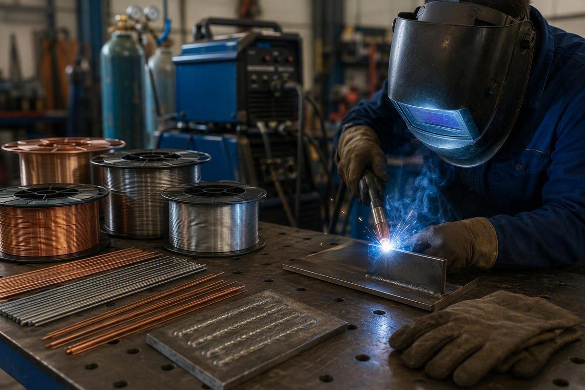
By Cole Brandt Updated September 2, 2026. Welder Facts identifies Brandt as a CWI-certified welder with two decades of structural, pipe, and fabrication-shop experience; these credentials are publisher-reported. About Welder Facts.
Related: Which MIG Solid Welding Wire Fits Your Job and Machine?.
Quick answer: wire diameter is a starting point, not a fixed thickness rule
For common solid-steel MIG welding, smaller wire usually gives the operator finer control on very thin sheet. Larger wire generally supports higher amperage and greater deposition when thicker work or larger welds require more filler metal.
That is a tradeoff, not a rule assigning one wire diameter to one material thickness. Operating ranges overlap substantially, so several diameters may be workable at the same current. No diameter guarantees penetration, heat control, or weld quality by itself.
Choose among the workable sizes by considering:
- Welding process and exact wire classification
- Base-metal alloy and thickness
- Required amperage
- Joint type, preparation, and fit-up
- Welding position
- Required deposition rate
- Transfer mode
- Shielding gas
- Welder, feeder, gun, and consumable-path capacity
- Operator control and production requirements
This article focuses primarily on common solid-steel MIG wire. Flux-cored wire is addressed separately because self-shielded and gas-shielded products have their own classifications, polarity requirements, positional capabilities, and parameter windows. Large structural wire and welding cable also require distinct selection methods. TIG filler selection is outside this chart’s scope; do not apply MIG amperage ranges or feed-rate formulas to TIG filler rod.
Precedence matters: follow the selected wire’s data sheet, equipment manuals, approved welding procedure specification (WPS), applicable code requirements, and site rules. Welder Facts’ terms specifically state that equipment manuals and site rules override its articles and that welding guidance assumes appropriate personal protective equipment and ventilation. Read the site terms.
Solid-steel MIG wire size chart by amperage
The following is a starter chart for solid-steel MIG wire only. It does not apply unchanged to flux-cored wire, aluminum, stainless steel, silicon bronze, or TIG filler.
| Solid-wire diameter | Starting amperage range | Suggested feed multiplier | Feed-rate formula |
|---|---|---|---|
| 0.023 in | 30–130 A | 3.5 in per amp | Amps × 3.5 = IPM |
| 0.030 in | 40–145 A | 2 in per amp | Amps × 2 = IPM |
| 0.035 in | 50–180 A | 1.6 in per amp | Amps × 1.6 = IPM |
| 0.045 in | 75–250 A | 1 in per amp | Amps × 1 = IPM |
These amperage ranges and multipliers are Miller’s starting guidance for welding steel with solid wire. The multipliers are suggested only when a machine manual or weld specification is unavailable; they are not universal settings or absolute product limits. The same guide describes approximately one amp per 0.001 inch of steel thickness as a preliminary rule of thumb, not a standard or guaranteed formula. See Miller’s solid-wire parameter guide.
The overlap is intentional. At a given estimated current, multiple diameters may fall within the published ranges, but they are not operationally identical. The cited starting multipliers call for a higher linear feed speed with smaller wire. Equal-current and equal-deposition comparisons, however, are not necessarily identical across wire products and transfer conditions.
Diameter also affects filler delivery, feeder-speed requirements, contact-tip and drive-roll setup, puddle behavior, and operator control. Amperage therefore narrows the choices without always identifying one uniquely correct size.
Worked example: 1/8-inch mild steel
One-eighth inch equals 0.125 inch. Applying the rough solid-steel MIG estimate:
0.125 inch × 1 amp per 0.001 inch ≈ 125 A
At 125 A, each diameter in the chart is nominally within its published starting range:
- 0.023 inch: 30–130 A
- 0.030 inch: 40–145 A
- 0.035 inch: 50–180 A
- 0.045 inch: 75–250 A
Using the suggested feed multipliers produces these initial calculations:
| Wire diameter | Calculation at 125 A | Approximate starting feed speed |
|---|---|---|
| 0.023 in | 125 × 3.5 | 438 IPM |
| 0.030 in | 125 × 2 | 250 IPM |
| 0.035 in | 125 × 1.6 | 200 IPM |
| 0.045 in | 125 × 1 | 125 IPM |
Miller’s published calculation gives 437.5 IPM for 0.023-inch wire, rounded here to 438 IPM, along with 250, 200, and 125 IPM for the other three diameters. These are starting calculations, not guaranteed settings. Review the worked parameter method.
This example demonstrates why thickness alone does not identify one correct welding wire size. All four pass the first amperage screen, but the practical choice still depends on the job.
Choose toward the smaller end when fine control is the priority and the feeder can deliver the required speed consistently. Choose toward the larger end when the approved procedure and equipment can use that wire’s supported current and deposition capacity—and when the position permits control of the resulting puddle.
For everyday work on 1/8-inch steel, 0.030- or 0.035-inch wire may provide a practical middle ground. That remains subject to the consumable data sheet, machine chart, joint, transfer mode, shielding gas, position, and procedure.
A seven-step method for choosing wire diameter
When multiple diameters fit the current range, use a process that eliminates unsuitable combinations before fine-tuning settings.
1. Identify the process and exact wire classification
Begin with what is actually being fed through the gun:
- Solid wire used with shielding gas
- Self-shielded flux-cored wire
- Gas-shielded flux-cored wire
- Metal-cored wire
- Another process-specific consumable
Do not sort these products by nominal diameter alone. Two wires marked 0.035 inch can have different polarity, shielding-gas, stick-out, position, and operating requirements. Record the complete classification and product name from the spool before consulting a chart.
2. Identify the base-metal alloy and thickness
The numerical chart above supports solid wire on steel. Do not generalize it to aluminum, stainless steel, silicon bronze, or another alloy.
Measure the thinnest member that the arc can damage, not merely the thickest piece in the assembly. Surface condition, coatings, joint preparation, and whether the weld is single- or multipass also affect the choice.
3. Estimate the required amperage
Use sources in this order:
- Approved WPS, where applicable
- Consumable manufacturer’s data sheet
- Power-source or feeder setup chart
- Tested shop procedure
- The thickness rule of thumb as a preliminary solid-steel MIG estimate
The estimate is a screening tool. If two or three diameters contain the estimated current, continue through the remaining steps rather than assuming the middle size is automatically correct.
4. Inspect the joint type and fit-up
A tight, consistently prepared joint can favor smaller filler when control is more valuable than deposition. A wider gap may benefit from a supported setup that supplies filler faster, but only if the base material, current, position, and procedure can tolerate it.
Also consider whether the joint is a butt, lap, fillet, or groove; whether the root is open; and whether access restricts the gun angle. Diameter cannot compensate for unacceptable fit-up or poor joint preparation.
5. Check the welding position
A large, fluid puddle that is productive in the flat position can become difficult to hold vertically or overhead. The exact wire classification must permit the intended position; diameter alone does not establish positional capability.
When position makes puddle control difficult, the answer may be a smaller supported diameter, another classification, a revised technique, or a procedure change—not merely lower voltage.
6. Check the entire machine and feed path
Before buying or loading the wire, verify:
- Power source output range
- Duty cycle at the intended current
- Feeder speed and torque capacity
- Correct drive-roll type and groove
- Compatible liner
- Correct contact-tip size
- Gun and cable rating
- Spool and hub compatibility
- Available polarity connections
- Shielding-gas compatibility and delivery capacity
A wire that fits an amperage chart is not usable if the feeder cannot deliver it reliably or the gun and power source cannot support the required output.
7. Test the complete combination
Run a coupon that reproduces the production conditions:
- Actual alloy and thickness
- Joint design and preparation
- Representative gap
- Welding position
- Wire product and diameter
- Polarity and shielding gas
- Stick-out and gun angle
- Expected travel conditions
- Machine and feed-system configuration
Inspect the result using the acceptance criteria required for the work.
Concise decision tree
Use this sequence:
- Which process and classification? Separate solid MIG, FCAW-S, and FCAW-G.
- Which alloy and thickness? Use only a chart that matches them.
- What current does the WPS, data sheet, or machine chart call for?
- Which supported diameters include that current?
- Does fit-up favor finer control or greater filler delivery?
- Does the classification allow the required position?
- Can the machine, feeder, gun, liner, tip, and drive rolls support it?
- Does a representative coupon meet the required result?
If the answer at any stage is no, move to another supported diameter, consumable classification, process, or equipment setup.
Thin sheet, everyday fabrication, and imperfect fit-up
Thinner metal does not always require the smallest wire available, but smaller solid wire is commonly easier to use on very thin sheet. It generally requires less output to melt and lets the operator meter filler in smaller increments, which can make a small puddle easier to control.
In one application-specific demonstration, Weld.com recommends 0.025-inch rather than 0.035-inch MIG wire for 22-gauge sheet described as approximately 0.030 inch thick. The visible source does not document the alloy, shielding gas, joint design, complete settings, travel speed, or test method, and the embedded video could not be reviewed from the supplied page. Treat the recommendation as a bounded example, not a general limit. View the Weld.com Facebook post.
Fit-up modifies the decision. As practical rather than standards-based guidance, Kevin Caron suggests approximately 0.024-inch MIG wire for a tight joint, 0.030 inch where a gap must be filled, and 0.035–0.040 inch for a large gap. His reasoning is that increasing diameter can deliver more filler, and he also advises changing the contact tip and machine setup when changing diameter. See Caron’s fit-up-based guidance.
That does not mean a wider gap automatically justifies larger wire. If the machine cannot run it smoothly, the joint is out of position, the procedure excludes it, or the thin edges cannot tolerate the setup, a larger diameter can compound the problem. Correcting fit-up or changing joint preparation may be better than trying to fill an excessive opening with more wire.
Why claims about “more heat” can conflict
Wire-size comparisons must state what is held constant:
- Equal wire-feed speed: larger wire feeds more cross-sectional metal per minute.
- Equal estimated amperage: different diameters can require different feed rates and can exhibit different melting or transfer behavior.
- Equal deposition and travel speed: smaller wire generally needs a higher linear feed speed, changing current density and other arc conditions.
An Airgas article attributed collectively to its editorial staff argues that, when deposition and travel rate are held constant, larger solid wire can have lower current density and may reduce over-penetration when crossing gaps. Its selected 1/8-inch fillet example compares 0.035-, 0.045-, and 0.052-inch wires. The article does not provide controlled test methods or a complete reproducible procedure, so it presents a plausible counterargument rather than proof that larger wire is generally superior on thin material. Review the equal-deposition argument.
For beginners and operators who mainly weld very thin sheet, a smaller diameter supported by the machine will often be easier to control. Larger solid wire can work in some thin-material applications, but it requires a deliberately matched combination of feed rate, voltage, travel speed, transfer behavior, fit-up, and technique.
Solid MIG versus flux-cored wire sizing
Do not copy the solid-steel MIG amperage chart directly to flux-cored wire. Cored products have classification-specific operating windows and cannot be grouped safely by diameter alone.
Solid wire is generally associated with relatively clean metal in an indoor or controlled shop environment and requires an external shielding-gas supply. Flux-cored products are commonly considered for repair, construction, thicker material, heavy-duty work, or outdoor conditions. However, “flux core” includes two distinct categories:
- Self-shielded flux core (FCAW-S): obtains shielding from the consumable and does not use an external gas supply.
- Gas-shielded flux core (FCAW-G): requires a compatible external shielding gas.
Do not assume these categories share polarity, gas requirements, positional capability, stick-out, or parameter ranges.
For self-shielded wire specifically, an affiliate-supported WeldGuru comparison associates 0.030 inch with thinner material and lower-powered machines, while 0.035 inch is associated with higher deposition and greater gap-filling ability. The publisher also says the difference may be modest for many users and that wire quality can matter as much as the nominal 0.005-inch size change. These are product-dependent tendencies, not universal operating or thickness limits. Read the qualified comparison.
Before selecting any flux-cored wire, verify on its data sheet:
- Exact classification and intended application
- Required polarity
- Whether shielding gas is required
- Compatible gas composition, if applicable
- Supported machine and wire diameter
- Material-thickness range
- Permitted welding positions
- Voltage and wire-feed window
- Required stick-out
- Single- or multipass limitations
- Mechanical-property and code requirements
A correctly classified, well-feeding 0.030-inch product may be a better choice than an unsuitable 0.035-inch product, and vice versa.
What must change when the wire diameter changes
Loading a different wire size is not merely a spool change. Check:
- Contact-tip size
- Drive-roll groove size and roll type
- Liner compatibility
- Feeder speed and torque capacity
- Gun and cable current rating
- Spool and hub support
- Polarity
- Product-specified stick-out
- Shielding-gas compatibility
- Output amperage and voltage range
- Power-source duty cycle
Manufacturer guidance for larger wire specifically emphasizes feeder torque, correctly sized gun and liner components, gas delivery, output, and duty cycle. Practical wire-change guidance also calls for matching the MIG contact tip to the new diameter. See Miller’s equipment considerations.
The contact tip must be intended for the selected wire diameter and product. Confirm the applicable tip, liner, drive-roll, and feeder requirements from the equipment and consumable manufacturers instead of assuming the existing path is compatible.
How wire-feed speed and voltage interact
In conventional constant-voltage MIG welding, wire-feed speed strongly affects amperage and deposition. Increasing feed speed presents wire to the arc faster, and the system responds with more current to melt it. Voltage primarily influences arc behavior and bead profile, including bead height and width.
Miller’s basic tuning guidance says an arc that repeatedly stubs into the work may need more voltage. An erratic arc that burns back toward the contact tip may indicate too much voltage. The guide also identifies appropriate penetration, a reasonably flat profile, suitable bead width, and sound toe tie-in as useful indicators. These are setup cues, not universal acceptance criteria.
Do not diagnose from one symptom alone.
Record successful settings only after testing the actual wire product, machine, joint, shielding gas, and position. A saved number from a different spool classification or gun setup may not reproduce the same arc.
When 1/16-inch and larger wire makes sense
Wire measuring 1/16 inch and larger is commonly described as large-diameter welding wire, although the threshold varies by application. In structural and heavy fabrication, its main advantage is deposition: it can fill deep grooves and large fillets faster when the joint and process require substantial weld metal.
The tradeoffs can include higher amperage, a larger and more fluid puddle, greater feeder-torque demand, compatible gun and liner requirements, sufficient machine duty cycle, and greater shielding-gas delivery in gas-shielded applications. Wire above 1/16 inch also often reduces out-of-position capability, although the exact classification determines the actual limit.
Examples cited in structural fabrication include 5/64-inch gas-shielded flux-cored wire, 3/32-inch self-shielded flux-cored wire for large and thick flat-position outdoor groove welds, and 5/64-inch self-shielded wire where more vertical capability may be needed. These examples concern particular process categories and applications; they are not interchangeable product recommendations or universal settings. See Miller’s large-wire examples and qualifications.
Before moving to large wire, verify:
- Exact classification
- Permitted position
- Required polarity
- Feeder torque and speed capacity
- Drive-roll groove and type
- Contact-tip and liner size
- Gun current capacity
- Shielding-gas type and delivery, if used
- Available output amperage
- Power-source and gun duty cycle
- WPS and code acceptance
- Coupon or procedure-test results
Diagnose symptoms without blaming diameter alone
A wire can be too large or too small for a particular setup, but the same symptoms can come from settings, hardware, contamination, fit-up, shielding, or technique.
| Symptom | How diameter might contribute | Other checks to make |
|---|---|---|
| Burn-through on thin sheet | Excessive filler delivery or a hard-to-control puddle may contribute | Voltage, wire-feed speed, travel speed, dwell time, joint gap, tack spacing, stick-out, gun angle, and technique |
| Poor fusion | The diameter may not operate well within the machine’s usable range | Actual amperage, travel speed, joint preparation, work angle, shielding, transfer behavior, contamination, and classification |
| Excessive spatter | Wire and operating range may be mismatched | Voltage, polarity, shielding gas, contamination, stick-out, circuit condition, and transfer stability |
| Arc stubbing | Feed rate may be too high for the voltage and arc conditions | Voltage, contact-tip compatibility, feed restriction, stick-out, and electrical connections |
| Burnback toward the tip | Feed may be interrupted or voltage may be excessive | Contact-tip condition, feed path, gun-cable bends, voltage, and stick-out |
| Unstable feeding | Diameter may not match the feed system | Tip size, drive-roll groove and type, liner compatibility, feeder capacity, and wire condition |
| Puddle difficult to control | The setup may be supplying more metal than the operator can manage | Position, voltage, travel speed, joint volume, gas, transfer mode, technique, and classification |
Burn-through
Do not respond automatically by installing smaller wire. First determine whether excessive voltage or feed, slow travel, a large joint gap, prolonged dwell, or technique is concentrating too much energy in the thin edge. A smaller supported diameter may improve control, but only as part of a matched setup.
Poor fusion
Larger wire is not an automatic cure. If the machine cannot run it in a stable and appropriate range, fusion may get worse rather than better. Verify amperage, travel speed, work and travel angle, joint preparation, shielding, classification, and whether the arc reaches the intended root and sidewalls.
Spatter and erratic arc
Check shielding-gas type and compatibility, voltage, polarity, surface contamination, wire condition, stick-out, and the electrical circuit. Diameter is only one variable. ESAB’s selection guidance recommends assessing weld soundness, puddle fluidity, bead shape, edge wetting, and spatter together rather than treating one observation as conclusive. Review ESAB’s MIG wire selection factors.
Feeding problems
Prioritize supported mechanical checks:
- Confirm that the wire and contact tip are compatible.
- Confirm the drive-roll groove and roll type.
- Check liner compatibility and condition.
- Confirm the feeder has sufficient capacity for the wire.
- Inspect the wire for rust, dirt, moisture, oil, or damage.
- Consult the equipment manual before changing feed-system adjustments.
Store wire clean and dry, protected from moisture, dust, oil, and other contamination. Changing voltage cannot correct a wire that is physically binding in the feed path.
After correcting obvious faults, stop experimenting on the production joint. Use a representative coupon, change one variable at a time, and evaluate the complete result.
Do not confuse consumable wire diameter with welding-cable gauge
Consumable electrode diameter and welding-cable gauge describe different components:
- 0.030 or 0.035 inch describes the diameter of consumable wire fed into the arc.
- 2 AWG, 1/0 AWG, or 4/0 AWG describes the conductor size of welding leads.
They are selected for different reasons and are not interchangeable sizing systems.
Welding cable is selected using welding current, the combined length of the electrode and work leads, duty cycle, ambient temperature, conductor properties, and insulation rating. Total circuit length means both leads together, not only the electrode lead. Longer circuits generally require larger conductors to control resistance and voltage drop. See IEWC’s welding-cable selection factors.
In the American Wire Gauge system, a lower gauge number denotes a thicker conductor. Sizes then progress beyond 1 AWG to 1/0, 2/0, 3/0, and 4/0, with 4/0 larger than 1/0.
As a bounded example, IEWC’s arc-welding table is based on a 4-volt drop and 60% duty cycle. Under those assumptions, it lists 4 AWG for 100 A at 100 feet, 1/0 AWG for 200 A at 200 feet, and 4/0 AWG for 300 A at 250 feet. Cable selection changes with circuit length, duty cycle, temperature, conductor, and insulation. Review the chart and its stated assumptions.
Do not use those examples outside their stated conditions, and never use a cable-gauge table to select consumable MIG or flux-cored wire.
Frequently asked questions
What MIG wire size is best for 1/8-inch steel?
There is no single size that is automatically best. As the worked example shows, several common solid-wire diameters can pass the preliminary amperage screen for 1/8-inch steel.
For general fabrication, 0.030- or 0.035-inch wire often provides a practical balance. Smaller wire can favor fine control, while larger wire can favor deposition when the machine, position, and procedure support it. Confirm the selection against the wire data sheet, machine chart, joint, shielding gas, transfer mode, and a representative test coupon.
Is 0.030- or 0.035-inch wire better for thin metal?
For solid MIG welding on very thin sheet, 0.030-inch wire will often be easier to control than 0.035-inch wire. That is a tendency, not a guarantee, and some especially thin applications may use an even smaller supported diameter.
For self-shielded flux core, keep the comparison separate. Product-specific guidance commonly associates 0.030 inch with thinner material and lower-powered machines and 0.035 inch with greater deposition and gap filling. Check the exact product’s permitted thickness, polarity, position, and parameter range.
Can I use the same chart for solid MIG and flux-core wire?
No. The chart in this article applies only to solid-steel MIG wire as starting guidance. Self-shielded and gas-shielded flux-cored products have classification-specific polarity, shielding-gas, stick-out, position, and operating requirements.
Use the flux-cored wire manufacturer’s data sheet and the equipment manual. Do not transfer solid-wire amperage ranges or feed multipliers without product documentation.
Do I need a new contact tip and drive rolls when changing wire size?
You normally need a contact tip intended for the new diameter. You must also verify that the drive-roll groove is the correct size and that the roll type suits the wire construction.
Depending on the change, you may also need a different liner or drive-roll set. Check feeder capacity, gun rating, spool support, polarity, and machine capacity before welding. Do not assume an existing feed path supports a new diameter merely because the wire can be pushed through it by hand.
Can different wire diameters produce the same weld size?
Yes. Different diameters can sometimes produce the same weld size when wire-feed and travel speeds are adjusted to provide the required deposition and joint fill.
They may not produce the same arc behavior, current density, puddle control, positional usability, or operator experience. Equal feed speed, equal amperage, and equal deposition are different comparisons. The acceptable combination must still meet the WPS, classification limits, machine capacity, and required weld quality.
The practical selection sequence is straightforward: identify the process and exact wire classification, estimate the required amperage, choose a supported diameter, account for joint fit and welding position, confirm every feed-system component and the machine’s capacity, then validate the complete setup on a representative coupon.
A welding wire size chart narrows the choices. The product data sheet, equipment manual, approved WPS, applicable code, site rules, and actual weld conditions make the final decision.