
How to Choose a Sound Welding Approach for Stainless Steel
Many common 300-series austenitic grades are welded without routine preheat, while some ferritic and martensitic grades require grade-specific thermal controls.
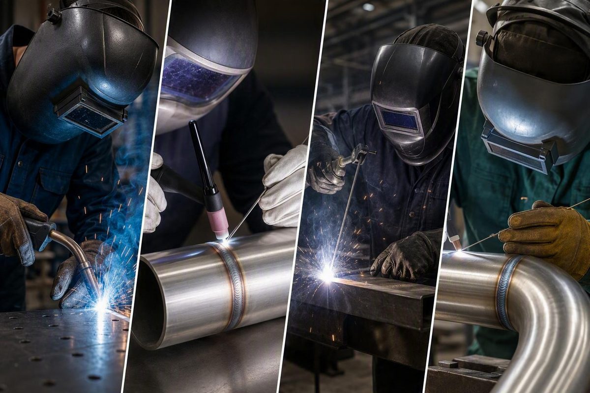
The short answer: Yes, but stainless is not carbon steel
Yes. Most stainless steels can be welded with familiar arc-welding processes, including:
- MIG, formally gas metal arc welding (GMAW)
- TIG, formally gas tungsten arc welding (GTAW)
- Stick, formally shielded metal arc welding (SMAW)
- Flux-cored arc welding (FCAW)
The important qualification is that stainless steel is a family of alloys, not one material with one universal welding procedure. The right approach depends on the alloy grade, material thickness, joint design, access, required appearance, mechanical demands, corrosion exposure and service temperature.
Stainless also behaves differently under the arc than ordinary carbon steel. Its lower thermal conductivity keeps heat concentrated near the weld, while its higher thermal expansion produces greater movement as the joint heats and cools. This combination makes distortion, changing fit-up and warping especially important concerns. It can also contribute to burn-through on thin sheet and high residual stress in restrained joints. Practical stainless-welding guidance identifies these thermal differences as major reasons not to treat stainless like carbon steel.
A weld can fuse without delivering the result the job requires. Poor alloy identification, unsuitable filler, excessive heat, inadequate shielding or contamination may contribute to:
- Burn-through and unacceptable distortion
- Hot or cold cracking
- Porosity or lack of fusion
- Heavy oxidation, heat tint or sugaring
- Embedded iron contamination
- Reduced corrosion performance
- Rust appearing after fabrication
The useful question is therefore not merely, “Can stainless steel be welded?” It is, “Which procedure will preserve the required mechanical and corrosion properties in this alloy and service environment?”
A sound workflow begins with the material and service requirements—not with a favorite process or generic machine-setting chart.
Identify the stainless grade before choosing a procedure
Stainless steel is a family of iron-based alloys. Differences in composition and microstructure affect cracking behavior, filler compatibility, corrosion performance and the possible need for thermal treatment.
Three broad families appear frequently in general fabrication:
- Austenitic stainless steels: This family includes widely used 300-series grades such as 304, 304L, 316 and 316L. These grades are common in tanks, tubing, sheet products and general corrosion-resistant fabrication.
- Ferritic stainless steels: These chromium-containing alloys have different thermal and metallurgical behavior from austenitic grades. Excessive heat or an unsuitable thermal cycle can adversely affect the weld area.
- Martensitic stainless steels: These grades can harden during cooling and may be particularly sensitive to cracking. Some applications require controlled preheat, interpass conditions, cooling or post-weld heat treatment.
They should not be forced into procedures written for familiar 300-series material.
Many common 300-series austenitic grades are routinely welded without preheat. That does not mean every austenitic application can skip it, or that the same practice applies to ferritic or martensitic grades. The alloy, thickness, restraint, filler, hydrogen control and applicable procedure all matter. A stainless welding procedure guide distinguishes the principal alloy families and their different thermal-control needs.
Establish the grade from traceable information
Do not identify an unknown stainless alloy by appearance alone. Use traceable material documentation or a qualified material-identification method appropriate to the job. Depending on the component and the governing quality system, useful information may include:
- Material markings and traceable stock labels
- Purchase records or mill documentation
- Drawings, bills of material or maintenance records
- Results supplied through an approved material-identification program
- Engineering or metallurgical evaluation of an unidentified installed component
This information is not a do-it-yourself identification formula. The required method and level of traceability depend on the consequences of selecting the wrong material.
Before choosing a procedure, establish as much of the following as the job requires:
- Both base-metal grades
- Whether either material has a low-carbon or stabilized designation
- Product form and thickness
- Previous heat treatment, if relevant
- Required strength and toughness
- Operating temperature
- Exposure to water, chlorides, chemicals or cleaning agents
- Whether the joint is structural, pressure-retaining, sanitary or code-governed
- Required inspection and surface restoration
Knowing only that a component is “stainless” is not enough to select filler or thermal controls confidently. Superficially similar grades may have different corrosion requirements, strength levels and responses to welding.
If the alloy is unknown, unusually sensitive or part of a critical system, stop and obtain qualified material identification and an appropriate procedure. Guessing can create a bead that looks acceptable while leaving unsuitable weld-metal chemistry or a damaged heat-affected zone.
TIG, MIG, stick, or flux-cored: choosing the process
No welding process is universally best for stainless steel. Process selection is a tradeoff among heat control, deposition rate, access, portability, cleanup, operator ability and required finish.
| Process | Heat control | Speed and deposition | Thin-material suitability | Appearance and cleanup | Portability and access | Operator demands | Common fit |
|---|---|---|---|---|---|---|---|
| TIG/GTAW | Close control of the arc and separate filler addition | Generally slower for manual deposition | Often well suited to thin or precise work | Can produce a narrow, controlled bead with little spatter; surface restoration may still be required | Requires torch access, reliable gas coverage and often two-hand coordination | High coordination and consistency required | Precision sheet, tubing, roots, small components and appearance-sensitive fabrication |
| MIG/GMAW | Controlled through voltage, wire feed, travel and transfer mode; pulse adds another control option | Faster deposition and readily adapted to repeated production | Suitable when transfer mode, equipment and procedure are configured for the material | Spatter and cleanup depend on transfer mode and setup | Convenient in shop production but dependent on shielding-gas coverage | Continuous wire delivery does not eliminate the need for stainless-specific setup | Repeated fabrication, longer joints, production work and automation |
| Stick/SMAW | Less fine control on thin sheet than TIG | Moderate; electrode changes interrupt work | Generally less convenient on thin sheet because of heat and burn-through risk | Slag must be removed between passes and after welding | Portable and useful where external shielding gas is impractical | Requires arc-length, travel and slag-control skill | Repair, field work and medium or thicker sections |
| Flux-cored/FCAW | Depends on wire, shielding arrangement and procedure | Continuous wire supports useful deposition | Application-dependent rather than a default thin-sheet choice | Slag and fumes require management; cleanup depends on the consumable | Equipment and shielding requirements vary by wire | Correct wire classification and technique are essential | Fabrication where a qualified stainless flux-cored procedure fits the access and production requirements |
TIG for control and finish
TIG is commonly selected for thin, precise or appearance-sensitive stainless work. The tungsten electrode creates the arc while filler, when needed, is added separately. This allows the operator to control arc placement, heat and filler addition independently.
That control is useful on thin sheet, small tubing, edge joints and parts with tight dimensional tolerances.
The tradeoffs are speed and skill. Manual TIG generally requires greater coordination and is less productive for long, repetitive fill passes. It should not automatically be described as stronger than MIG. Weld strength depends on joint design, penetration, filler, defects, metallurgy and compliance with the applicable procedure—not on the process name alone.
MIG for production and repeatability
MIG continuously feeds a consumable wire electrode. It is commonly chosen for faster deposition, repeated fabrication and automation. Although broad comparisons sometimes label MIG as a thick-material process, properly configured GMAW can also be used on thin stainless.
Transfer mode is central to that capability. Stainless MIG may use short-circuit, spray or pulsed transfer where the equipment, wire and procedure permit. Pulsed MIG can provide spray-type transfer at a lower average current, helping reduce spatter and melt-through risk in suitable thin-material applications. Lincoln Electric’s stainless MIG guidance distinguishes these transfer modes and their setup requirements.
Pulsed MIG is not a cure for poor fit-up or incorrect settings. The power source must support the required program, and wire classification, gas, contact-tip-to-work distance, travel and joint design still have to work together.
Stick for portability and repair
Stick welding is viable for stainless-to-stainless joints and for some stainless-to-carbon-steel combinations. Flux on the electrode supplies shielding and leaves slag over the deposit.
Its limitations become more obvious on thin sheet. The process can put too much heat into a small section, increasing burn-through and distortion risk. Starts, stops and slag removal also make it less convenient for small cosmetic work. It is generally a better candidate for medium or thicker material under an appropriate electrode and procedure.
Flux-cored welding
Stainless flux-cored consumables provide another option. FCAW should be evaluated according to wire classification, shielding requirements, welding position, mechanical properties, corrosion requirements and manufacturer instructions.
Prepare the joint without contaminating the stainless
Joint preparation is part of the welding procedure, not housekeeping performed after the important decisions. Stainless needs clean surfaces, controlled fit-up and protection from carbon-steel contamination.
Pre-weld checklist
Before striking an arc, confirm:
- [ ] Grade: Both base metals are identified to the level required by the job.
- [ ] Service: Strength, corrosion, temperature, sanitary and inspection requirements are understood.
- [ ] Joint design: Groove, root opening, land, backing and access suit the process and required penetration.
- [ ] Fit-up: Gaps and alignment are within the applicable procedure.
- [ ] Accessibility: The torch, gun or electrode can be positioned without compromising shielding or technique.
- [ ] Movement control: Clamps, fixtures, tack sequence and welding sequence account for thermal expansion.
- [ ] Surface condition: Oil, grease, dirt, paint, moisture, burrs and oxides have been removed.
- [ ] Tools: Brushes, abrasives, files and grinding equipment are dedicated to stainless or verified free of carbon-steel residue.
- [ ] Consumables: Filler classification, condition and storage are suitable.
- [ ] Shielding: Gas, delivery system and any required root-side protection have been confirmed.
- [ ] Electrical setup: Polarity and machine configuration match the process and consumable.
- [ ] Heat strategy: Tack pattern, sequence and any procedural preheat or interpass controls are ready.
- [ ] Safety: Extraction, screens, PPE and fire controls are in place.
Clean immediately before welding
Remove grease, cutting fluids, marking compounds, dirt, paint, moisture and loose oxide from the weld area. Clean beyond the groove so contamination is not drawn into the pool during manipulation.
Use only cleaners allowed by the documented shop procedure, material requirements and workplace rules. Allow volatile products to dissipate before welding, and never weld over an unidentified coating or solvent residue.
Burrs, heavy scale and existing oxide can interfere with fit-up and shielding. On previously welded or heat-tinted surfaces, prepare the area according to the requirements of the next welding operation and the component’s corrosion specification.
Separate stainless tools from carbon-steel tools
A brush can have stainless bristles and still be unsuitable if it was previously used on carbon steel. Grinders, flap discs, wire wheels, files, blasting media, clamps and dirty fabrication tables can all transfer iron particles onto stainless.
Clearly marked stainless-only tools and segregated work areas reduce this risk. Fabrication guidance recommends separating stainless preparation tools from equipment contaminated by carbon steel.
Tool separation controls one contamination source. It does not compensate for unsuitable filler, excessive oxidation, poor shielding or an inappropriate thermal cycle.
Plan fit-up, tacks and restraint together
Because stainless expands substantially when heated, small fit-up errors can become larger during welding. Establish the required root opening and alignment before tacking. Use enough tacks to stabilize the joint, but avoid oversized tacks that add unnecessary heat or obstruct the final weld.
Fixtures should hold the assembly accurately without creating excessive restraint. The right balance depends on the geometry, thickness, alloy and procedure.
Clean and inspect tacks before incorporating them into the weld. Defective or heavily oxidized tacks should not simply be buried under later passes.
Select filler, shielding gas, and electrical setup by application
Filler and shielding choices determine more than bead appearance. They influence weld-metal composition, cracking resistance, mechanical properties and corrosion performance.
Start with compatibility, not exact matching as an absolute rule
For matching stainless alloys, filler with a compatible and broadly similar composition is a sensible starting principle. It is not a universal rule.
Common bounded examples include:
- 308L-type filler for several common 300-series applications, particularly compatible 304-family work
- 316L-type filler for compatible 316 applications
- 309-type or E309L consumables for some austenitic-stainless-to-carbon-steel joints
These examples do not replace a filler-selection table, consumable manufacturer recommendation or welding procedure specification. Final selection depends on:
- Both base-metal compositions
- Dilution from each side of the joint
- Expected weld-metal microstructure
- Cracking resistance
- Strength and toughness requirements
- Corrosion exposure
- Service temperature
- Heat treatment
- Code or customer requirements
Mixed stainless grades and dissimilar-metal joints may call for an over-alloyed filler rather than a nominal match to either side.
Match MIG shielding gas to the transfer mode
There is no universal stainless MIG gas. A blend that supports one transfer mode may perform poorly or produce unsuitable weld chemistry in another.
Process-specific examples include argon with 1% or 2% oxygen for the cited spray-transfer applications, a blend of 90% helium, 7.5% argon and 2.5% carbon dioxide for the cited short-circuit guidance, and argon with 1% oxygen for the cited pulsed process. The same guidance warns that carbon dioxide can affect corrosion resistance in multipass short-circuit welds. These mixtures are transfer-mode-specific examples, not universal prescriptions. Lincoln Electric documents the mixtures and their respective applications.
Select gas from the approved procedure or current wire and equipment documentation. Confirm that it supports the intended transfer mode and required corrosion performance. Do not copy a familiar carbon-steel MIG blend onto stainless without verification.
Verify polarity and machine configuration
For the stainless GMAW applications covered by the supplied technical guidance, direct current electrode positive (DCEP) is used in most cases. Stainless GTAW is commonly described using direct current electrode negative (DCEN). These are process-specific starting principles, not permission to ignore the consumable label, machine manual or welding procedure.
Before welding, verify:
- Polarity
- Wire-feed roll type and pressure
- Liner and contact-tip compatibility
- Tungsten type and preparation for TIG
- Gas connections and delivery integrity
- Inductance, pulse program or arc-control functions where applicable
- Electrode classification and permissible current for stick
- Machine duty cycle
Universal amperage, voltage, wire-feed, gas-flow and electrode-size recommendations are inappropriate here. Settings depend on the joint, material thickness, position, transfer mode, equipment and procedure. Use a verified starting schedule, test on representative material and qualify the result where required.
Control heat to limit distortion, burn-through, and cracking
Heat control is not simply a matter of turning down amperage. Total heat input and its effects are influenced by current, voltage, travel speed, arc length, bead size, sequencing, joint geometry and time between passes.
Stainless steel’s low thermal conductivity concentrates heat around the weld instead of carrying it away quickly. Its comparatively high thermal expansion also causes substantial movement. The result can include:
- Localized overheating
- Shrinkage and angular distortion
- Buckling or oil-canning in sheet
- Changing root gaps
- Burn-through
- High residual stress
- Grade-dependent cracking
- Heavy oxidation and reduced corrosion performance
A practical heat-control workflow
-
Start with a suitable joint design. Avoid depositing more weld metal than the joint requires. Excessive groove volume increases welding time, heat and shrinkage.
-
Establish accurate fit-up. An inconsistent gap forces the welder to dwell, add filler or bridge openings, complicating heat control.
-
Secure the work. Use fixtures and clamps that maintain alignment while allowing the planned welding sequence.
-
Plan the tacks. Distribute tacks to hold the gap and limit cumulative movement. Treat them as part of the finished joint if they will remain.
-
Choose a process suited to the thickness and access. TIG offers close manual control. Properly configured pulsed MIG can reduce average current while retaining a useful transfer mode.
-
Use an intentional sequence. Where the procedure permits, balanced sections, alternating sides or moving around the assembly may distribute shrinkage better than completing one long weld from end to end.
-
Avoid unnecessary dwelling and oversized beads. More weld metal is not automatically more strength. It may simply add heat and distortion.
-
Monitor interpass conditions when required. Do not begin another pass merely because the surface looks ready. Follow the specified interpass controls for the alloy and joint.
-
Allow controlled cooling. Do not improvise rapid quenching or forced cooling unless the approved procedure permits it. Cooling conditions can affect residual stress and grade-dependent cracking.
-
Inspect before continuing. Watch for movement, oxidation, cracking, incomplete cleaning and deteriorating gas coverage between passes.
Preheat and postheat are grade-dependent
Many familiar 300-series austenitic stainless welds do not routinely require preheat. Some martensitic and ferritic grades may require tightly controlled preheat, interpass temperature, cooling or post-weld treatment.
“Stainless does not need preheat” is therefore no safer as a blanket statement than “stainless always needs preheat.” Apply the identified grade’s documented procedure.
Discoloration is process information
Heat tint forms where hot stainless reacts with the atmosphere. Severe oxidation or root-side sugaring can indicate excessive heating or inadequate protection and may impair corrosion performance.
Do not judge acceptability solely from color in an online photograph. Permissible tint and the required response depend on the application.
Where corrosion performance matters, surface restoration is a separate production step. The acceptable method must come from the applicable corrosion specification or documented shop procedure; it cannot be selected from appearance alone. Welding is not necessarily complete merely because the arc has stopped.
Welding stainless steel to mild or carbon steel
Austenitic stainless steel can be welded to carbon or low-alloy steel using TIG, MIG, stick and other full-fusion processes under an appropriate procedure. The main challenge is managing dilution and the different behavior of the two base metals.
When the weld pool melts both materials, the final weld-metal chemistry is not simply the chemistry printed on the filler package. Carbon steel dilutes the stainless filler, potentially reducing alloy content and changing cracking behavior.
For a bounded example, when joining 304 austenitic stainless to carbon steel for ambient-temperature service, 309-type filler is commonly preferred over 308-type filler because it better accommodates dilution. The British Stainless Steel Association presents this recommendation as conditional on the metals and service, not as a universal answer for every stainless-to-steel joint.
Filler selection changes when the stainless family, low-alloy steel chemistry, strength requirement, heat treatment, corrosive environment or operating temperature changes.
Decide preheat from the steel side as well
Preheat for a dissimilar joint may be driven by the carbon or low-alloy steel rather than by the austenitic stainless. Consider:
- Carbon content and hardenability
- Steel grade
- Section thickness
- Joint restraint
- Hydrogen control
- Ambient and base-metal conditions
- Filler requirements
- Applicable code
Do not apply one preheat rule to every mild-steel-to-stainless joint. Equally, do not assume that the absence of preheat on ordinary 304 fabrication means the carbon-steel side never needs it.
Remove zinc before welding galvanized material
If the carbon-steel component is galvanized, remove zinc near the joint as required by the approved procedure so it does not enter the fusion zone. Molten zinc can contribute to embrittlement and may compromise the joint or nearby corrosion performance.
Coating removal before welding and coating restoration afterward are separate requirements. The completed joint needs a suitable protective system restored in accordance with the job specification. Removing zinc without restoring protection leaves exposed carbon steel vulnerable.
Account for galvanic corrosion
In a wet or aggressive environment, stainless steel and carbon steel can form a galvanic couple, with the carbon-steel component generally more vulnerable. A sound protective coating extending across the weld and adjacent steel can help interrupt the corrosion cell, provided the coating remains intact.
Detail the assembly to avoid water traps, crevices and coating discontinuities. Material selection and corrosion protection for marine, chemical or persistently wet service deserve engineering review.
The same dissimilar-welding guidance identifies zinc removal, coating restoration, galvanic corrosion and elevated-temperature expansion differences as procedure-dependent concerns. It also warns that long-term hot service can change filler and joint requirements. Treat elevated-temperature stainless-to-carbon-steel work as an engineering and procedure-qualification case.
Diagnose discoloration, rust, cracking, and poor weld behavior
Troubleshooting should begin with the symptom and the complete procedure. Changing amperage without examining grade, gas, filler and fit-up can conceal one problem while creating another.
Distortion or burn-through
Investigate:
- Excessive total heat input
- Slow travel or unnecessary dwelling
- Process and transfer-mode suitability
- Oversized welds
- Poor or inconsistent fit-up
- Insufficient tack support
- Unbalanced welding sequence
- Inappropriate restraint
- Material thinner than assumed
- Repeated repairs in the same area
On thin work, replacing one long continuous weld with an approved balanced sequence may help. A different process or suitable pulsed program may also be appropriate. Do not compensate for a large gap by repeatedly washing the edges with the arc.
Cracking
Investigate:
- Whether the stainless family and exact grade were correctly identified
- Filler compatibility and dilution
- Required preheat, postheat or controlled cooling
- Excessive restraint
- Hydrogen or moisture sources
- Heat input and bead shape
- Arc strikes or defective tacks
- Service-related cracking rather than fabrication cracking
Do not simply weld over a crack. Establish its full extent, remove it by an approved method and correct the cause before repair.
Blackening, severe discoloration or sugaring
Investigate:
- Inadequate shielding-gas coverage
- Drafts or leaks
- Incorrect gas selection
- Excessive torch angle or arc length
- Contaminated gas lines or components
- Excessive heat and slow travel
- Loss of required root-side protection
- Shielding practices that do not protect the weld and adjacent hot metal as required
Color alone is not a universal pass/fail test.
Rust after welding
Investigate:
- Carbon-steel brushes, abrasives or work surfaces
- Embedded iron from nearby grinding
- Excessive heat tint or oxidation
- Unsuitable filler
- Incomplete post-weld cleaning or restoration
- Damage during handling or installation
- Exposure more aggressive than the alloy was selected to withstand
Shared tools are a common and preventable contamination source. Stainless-welding guidance warns that transferred carbon-steel residue can cause later rust even when the base stainless was originally corrosion resistant. Kloeckner Metals identifies dedicated tools and clean preparation as controls against contamination-related rust.
Porosity or an unstable weld pool
Check:
- Oil, moisture, paint and oxide
- Wet or damaged consumables
- Gas-cylinder contents
- Gas leaks, restrictions and delivery stability
- Drafts disrupting the shield
- Torch or gun angle
- Arc length and stickout
- Polarity
- Drive-roll pressure and wire feeding
- Work connection and cable condition
- Whether the gas suits the transfer mode
An attractive bead does not prove adequate penetration, fusion, mechanical integrity or restored corrosion resistance. Visual inspection is one part of acceptance, not the whole decision.
Defects in structural, pressure, sanitary, marine, high-temperature or corrosion-critical work call for procedure review and evaluation by appropriately qualified personnel. Required examination may include methods beyond visual inspection.
Treat stainless-welding safety as part of the procedure
Stainless-welding safety is not an accessory to production. Welding can generate hazardous chromium-containing fumes, intense ultraviolet radiation, hot metal, noise and electrical hazards. Stainless must not be treated as safe merely because finished stainless products are associated with clean or sanitary applications. ESAB’s stainless-welding safety guidance identifies chromium-containing fumes, ultraviolet radiation and electric shock as hazards requiring control.
Control fumes at the source
Use ventilation or local exhaust extraction appropriate to the process, work area and exposure assessment. Keep fumes out of the breathing zone and avoid placing the head directly in the plume. Extraction must be arranged under the site’s approved procedure so that it captures emissions without compromising required shielding.
Confined, enclosed or poorly ventilated spaces require a task-specific hazard assessment and controls.
Respirator selection cannot be made safely from a generic article. Ventilation, work positioning, process selection and respiratory protection should be integrated rather than treated as interchangeable shortcuts.
Protect the welder and nearby personnel
Use protection selected for the process, exposure and task, including:
- An appropriate welding helmet and filter shade
- Safety glasses under the helmet
- Flame-resistant body, hand and foot protection
- Hearing protection where required
- Protection from grinding and chipping debris
- Protection from contact with live electrical components and damp conditions
- Screens or barriers for nearby personnel
- Fire prevention and hot-work controls
Cover exposed skin and control access around the arc. Ultraviolet radiation can affect nearby people even when they are not looking directly at the weld. Manufacturer safety guidance calls for fume controls, electrical precautions and suitable eye, ear and body protection; site requirements determine the specific equipment and control measures. Follow the current safety documentation for the process and workplace.
Read the current power-source, feeder, torch and consumable instructions before use. Review safety data sheets and follow site rules, hot-work permits and applicable welding requirements. Welder Facts’ terms state that its articles are informational and that equipment manuals and site rules take precedence.
Structural, pressure-retaining, sanitary, marine, elevated-temperature and code-governed work should use a qualified welding procedure and appropriate oversight. The same boundary applies when the alloy is unknown or corrosion failure could harm people, equipment or the environment.
Frequently asked questions
Can stainless steel be MIG welded?
Yes. Stainless can be MIG welded with compatible wire, shielding gas selected for the intended transfer mode and a suitable GMAW procedure. Short-circuit, spray and pulsed transfer may be available depending on the equipment and application.
Do not copy generic carbon-steel gas or settings charts. Verify the wire, gas, polarity, transfer mode and machine program against current manufacturer documentation and the applicable procedure.
Can stainless steel be stick welded?
Yes. SMAW can join stainless to stainless and can make some stainless-to-carbon-steel joints with the correct electrode and procedure.
Stick is often practical for field repairs and medium or thicker sections. It is generally less convenient on thin sheet because of burn-through risk and the need for slag removal.
Does stainless steel need to be preheated before welding?
Not always. Many common 300-series austenitic grades are welded without routine preheat, while some ferritic and martensitic grades require grade-specific thermal controls.
Dissimilar joints may also require preheat because of the carbon or low-alloy steel. Determine the requirement from the identified materials and approved procedure, not from a blanket rule for stainless.
Can stainless steel be welded to mild steel?
Yes. Austenitic stainless can be joined to mild or carbon steel with suitable fusion-welding processes.
For a common 304-stainless-to-carbon-steel joint in ambient service, 309-type filler is often preferred over 308-type filler to accommodate dilution. Other alloys, coatings, environments and service temperatures can require a different solution.
Why can stainless steel rust after it has been welded?
Possible causes include transferred iron, embedded grinding debris, severe oxidation, inadequate shielding, unsuitable filler, incomplete surface restoration or exposure beyond the selected alloy’s corrosion capability.
Diagnose the cause before polishing away the stain. Cosmetic cleaning alone may leave contamination, unsuitable weld metal or damaging oxidation in place.
Choose the procedure before striking the arc
Stainless steel is weldable, but it is not forgiving of guesswork. Identify the alloy and service conditions first, choose a suitable process and compatible filler, use process-specific shielding, keep the joint and tools clean, control heat and protect both the welder and the finished surface.
Generic settings cannot replace current equipment instructions, consumable data, applicable codes or a qualified procedure. When the alloy is unknown—or the weld is structural, pressure-retaining, sanitary, marine, high-temperature, corrosion-critical or otherwise safety-critical—obtain qualified technical oversight before welding.