
How to Set Up a MIG Welder for Stainless Steel Without Guessing
One cited setup pairs helium-rich tri-mix with short-circuit, argon plus 1-2% oxygen with spray, and argon plus 1% oxygen with pulsed transfer.
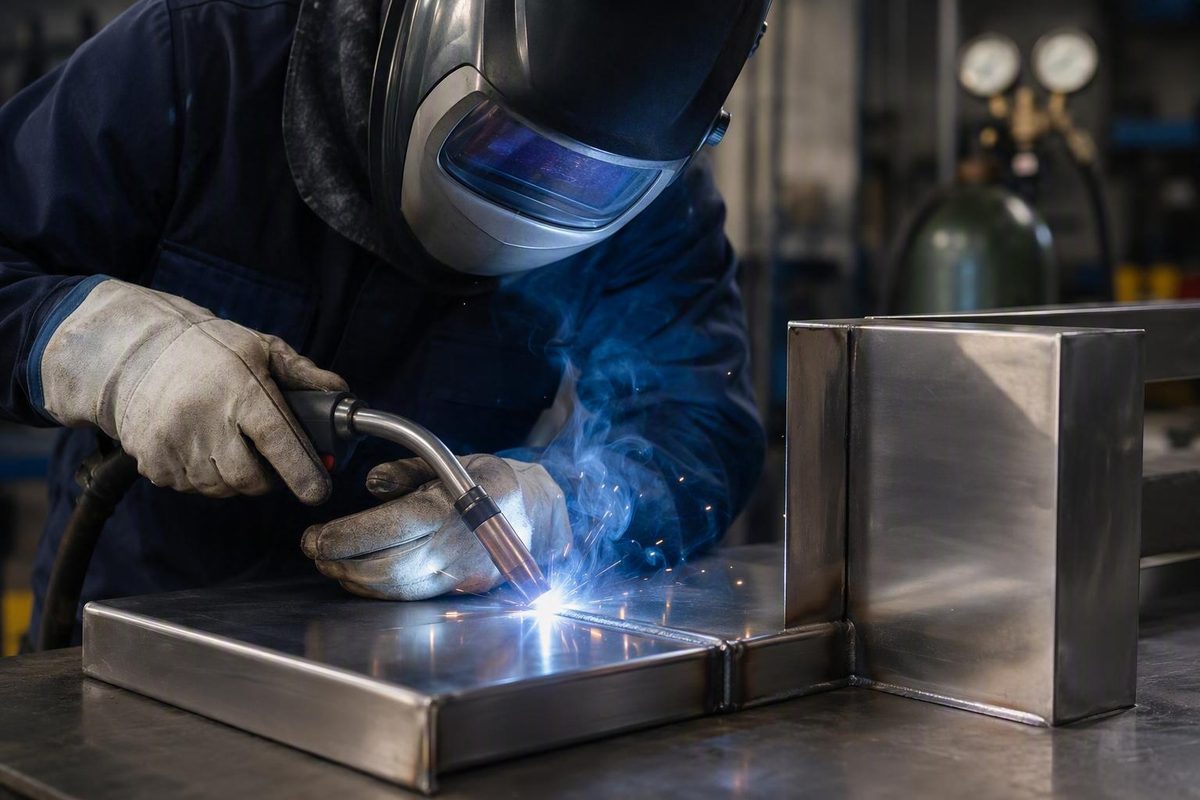
MIG welding stainless steel is not a matter of loading any stainless wire, connecting the gas used for mild steel, and copying a settings chart. A reliable setup depends on the identified alloy, filler classification, transfer mode, shielding gas, polarity, feed system, joint preparation, welding position, and intended service.
This guide focuses on gas-shielded, solid-wire MIG/GMAW for common 300-series austenitic stainless steels, especially 304 and 316. It provides a practical setup and tuning sequence, not a qualified welding procedure specification.
Can You MIG Weld Stainless Steel—and When Is MIG the Right Process?
Yes. Stainless steel can be welded with solid-wire MIG when the machine, filler wire, shielding gas, polarity, transfer mode, and procedure suit the alloy and joint.
MIG—formally gas metal arc welding, or GMAW—uses a continuously fed consumable wire electrode. The wire carries current, establishes the arc, and becomes filler metal as it melts. Shielding gas delivered through the gun protects the weld area from the surrounding atmosphere. TIG/GTAW instead uses a non-consumable tungsten electrode and may use separately added filler; this comparison explains the basic process distinction.
For solid-wire stainless MIG, the machine and feeder should provide:
- Adjustable voltage and wire-feed speed
- Stable feeding at the selected wire diameter
- A shielding-gas connection and controllable delivery
- The polarity required by the selected wire
- Enough usable output for the intended transfer mode
- Sound cables, connectors, gun components, and work-lead connections
Pulse controls can broaden the useful operating range, but they are not mandatory for every stainless joint. A conventional machine can weld stainless when its output, wire, gas, transfer mode, and joint requirements are compatible.
This guidance should not be applied unchanged to duplex, ferritic, martensitic, precipitation-hardening, or specialty stainless steels.
MIG or TIG?
Strength and suitability depend on the base metal, filler, joint design, procedure, execution, and acceptance criteria.
In general:
- Choose MIG when productivity matters. Continuously fed wire suits longer runs, repeated joints, and production work.
- Consider TIG when precision and appearance dominate. TIG often provides finer manual control on thin, intricate, or finish-sensitive work.
- Consider pulsed MIG when productivity and heat control both matter. A compatible pulse program can make spray-like transfer useful on thinner or positional work.
- Account for access. A MIG gun may be convenient in one joint and too bulky in another.
- Account for operator capability. Familiarity with the equipment and transfer mode can matter more than a broad process comparison.
Commercial process comparisons commonly characterize MIG as faster and TIG as slower but more precise. These are tendencies rather than hard limits; thickness, production rate, appearance, equipment, and operator skill all affect the choice.
Use this decision framework:
- Material: Is the exact stainless grade known?
- Thickness and joint: What fit-up, root condition, access, and welding position must be handled?
- Production: Is the priority speed, one-off control, or repeatability?
- Appearance: Is spatter or bead cleanup acceptable?
- Equipment: Can the machine support the necessary polarity, gas, wire, and transfer mode?
- Operator: Which process can be controlled consistently?
- Qualification: Does the work require an approved procedure or formal inspection?
This article concerns gas-shielded, solid-wire MIG/GMAW. It does not cover self-shielded flux-cored welding and should not be read as a general endorsement of “gasless MIG” for stainless.
Identify the Stainless and Build the Correct Wire-Feed Setup
Filler selection begins with alloy identification. Check reliable markings, drawings, purchasing records, material certificates, or an appropriate identification method before choosing wire.
Consider:
- Both base-metal grades
- Whether the joint is stainless-to-stainless or dissimilar metal
- Dilution from each base metal
- Joint design and number of passes
- Required mechanical properties
- Service temperature
- Corrosive exposure
- The applicable specification or approved procedure
ER308-, ER309-, and ER316-family wires are not universal substitutes. As one bounded example, YesWelder identifies ER308 or ER308L for 308 stainless and also lists ER308 for grades 301, 302, 304, and 305. The same commercial guide discourages the usual 75% argon/25% CO2 mild-steel blend for the stainless application it discusses. Treat these as starting points to verify, not as a complete filler or gas specification; the guidance is explicitly centered on common 300-series austenitic stainless.
For 316, dissimilar-metal joints, unknown stainless, or corrosion-critical service, do not extrapolate from the 304 example. Verify the exact wire classification through current wire-manufacturer data, the applicable filler-metal specification, or an approved WPS.
Confirm polarity
For most solid-wire stainless applications covered here, use DCEP: direct-current electrode positive.
That means:
- The MIG gun or electrode connection is positive
- The work lead is negative
Check the machine’s connection diagram rather than relying on where the leads were attached for a previous job. The required arrangement is determined by the selected wire and equipment instructions.
Inspect the complete feed path
Before striking an arc, inspect the feed path from spool to contact tip:
- Confirm the wire classification and diameter.
- Install the correct contact-tip size.
- Check the tip for wear, blockage, or an enlarged bore.
- Confirm that the liner is clean, correctly sized, and not kinked.
- Check inlet and outlet guide alignment.
- Install the roll type specified by the wire and feeder manufacturer.
- Apply only enough roll pressure for reliable feeding.
- Set spool drag so the spool stops without unnecessarily resisting normal feed.
- Straighten tight gun-cable loops.
- Jog the wire and verify smooth, consistent delivery.
Do not respond to every feed problem by tightening the rolls. First inspect the liner, tip, guides, cable routing, spool drag, and roll selection.
If they do not grip stainless wire reliably, V-knurled rolls are one manufacturer recommendation. That same guidance favors stainless-dedicated liners, rolls, and preparation tools, but the wire and feeder manufacturers’ instructions should determine the final configuration.
Where practical, reserve a stainless liner, contact tips, guides, drive components, brushes, and abrasives for stainless work. At minimum, inspect and clean components previously exposed to carbon-steel wire or grinding debris.
Choose Shielding Gas by Transfer Mode, Not by Habit
No supplied source establishes one shielding-gas blend as correct for every stainless alloy, wire, transfer mode, machine, thickness, joint, and position. Select the transfer mode and gas together, then verify the combination against current wire data and equipment instructions.
| Transfer mode | Cited gas example | Intended role | Verification warning |
|---|---|---|---|
| Manual short-circuit | 90% helium, 7.5% argon, 2.5% CO2 | Helium-rich tri-mix for short-circuit stainless transfer | Confirm compatibility with the wire, machine, joint, and service |
| Conventional spray | Argon with 1–2% oxygen | Argon-rich gas supporting spray transfer in cited applications | Do not assume approval for every wire or power source |
| Pulsed transfer | Argon with 1% oxygen | Argon-rich example for pulsed spray-like transfer | Use the machine’s compatible pulse program |
| Application-dependent option | 98% argon, 2% CO2 | Low-CO2 stainless option | Not established as suitable for every mode or service |
Lincoln Electric pairs the helium-rich tri-mix with short-circuit transfer, argon with 1–2% oxygen with conventional spray, and argon with 1% oxygen with pulsed transfer. It also warns that CO2 can affect corrosion resistance in multipass short-circuit welds, although an argon-CO2 blend may be used in some single-pass work. These are mode-specific examples, not one universal gas prescription.
The 98% argon/2% CO2 option is identified in Miller’s stainless guidance, which also recommends keeping carbon dioxide below 5% for the applications it discusses. The selected blend still must match the process and consumable.
This matters especially with pulsed or synergic machines.
The common mild-steel argon/CO2 blend is not a preferred default for the 300-series application covered here.
Gas composition is only part of the system
Even the correct cylinder contents cannot compensate for poor delivery. Gas performance depends on:
- Actual composition
- Regulator and flowmeter compatibility
- Hose and fitting condition
- Nozzle and diffuser cleanliness
- Nozzle-to-work position
- Gun angle and stickout
- Drafts and local air movement
- Joint geometry
- Flow setting and turbulence
Do not treat an isolated flow figure as universally correct. Begin with the machine, wire, and gas supplier’s guidance, then evaluate coverage under actual shop conditions.
Before welding:
- Verify the cylinder contents.
- Install the regulator according to the equipment and supplier instructions.
- Inspect hoses, fittings, and connections.
- Confirm that gas reaches the gun.
- Remove spatter from the nozzle and diffuser.
- Position the nozzle to maintain coverage.
- Reduce fans, open-door drafts, and crossflow where practical.
- Do not assume that continually increasing flow will correct a leak, blockage, draft, or poor gun position.
Short-Circuit, Spray, or Pulsed: Select the Transfer Mode
Transfer mode determines how molten wire crosses the arc. It also affects current, heat behavior, puddle fluidity, usable position, spatter, gas selection, and equipment requirements.
| Factor | Short-circuit | Conventional spray | Pulsed |
|---|---|---|---|
| Relative current | Generally lower | Relatively high | High-current pulses with lower background current |
| Heat behavior | Useful where lower overall input is needed, but technique-sensitive | Fluid puddle with sustained heat | Spray-like transfer at lower average current than conventional spray |
| Position | Often adaptable, subject to puddle control and procedure | More limited by a fluid puddle | Often more suitable for positional work than conventional spray |
| Spatter | Can be significant if poorly balanced | Usually low when stable | Commonly low with a compatible program |
| Thin-material risk | Can help control melt-through | Greater burn-through risk | Can reduce melt-through risk relative to conventional spray |
| Gas | Mode-specific tri-mix is one cited option | Argon-rich gas capable of supporting spray | Argon-rich blend matched to the pulse program |
| Equipment | Conventional machine may work | Requires sufficient current and voltage | Requires a pulse-capable source and compatible program |
Short-circuit transfer
In short-circuit transfer, the wire repeatedly contacts the puddle, transfers metal, and re-establishes the arc. It is commonly considered for thinner work, root passes, and joints where conventional spray would create excessive fluidity or heat.
Its success depends heavily on:
- Stable wire delivery
- Voltage-to-wire-feed balance
- Inductance or related arc controls, where available
- Consistent stickout
- Fit-up and root gap
- Gun angle and travel speed
- Suitable shielding gas
A relatively cool-feeling arc does not prove that the weld has adequate fusion.
Conventional spray transfer
Conventional spray uses relatively high current to transfer small droplets across the arc without repeated shorting. It can provide productive deposition and a smooth arc, but its fluid puddle and sustained heat may make it unsuitable for thin material or some out-of-position joints.
Lincoln Electric lists 0.030-, 0.035-, and 0.045-inch wire as common stainless spray sizes and also discusses wire up to 1/16 inch. Those sizes are not interchangeable settings: current, gas, wire type, joint, and machine capability still determine the usable range. The source’s isolated high-current example for larger wire should not be generalized to smaller diameters.
Pulsed transfer
Pulsed MIG alternates strong high-current pulses with lower-current intervals. A sufficiently strong pulse transfers a molten droplet; the background interval maintains the arc without sustaining conventional spray current continuously.
Potential advantages include:
- Lower average current than conventional spray
- Reduced spatter
- Useful penetration with less melt-through risk
- Better control on thinner material
- Improved suitability for some out-of-position work
- Less accumulated heat when correctly programmed and applied
Pulse is beneficial, not mandatory. A conventional welder may be suitable for a compatible short-circuit or spray application. Conversely, a pulsed machine does not remove the need to identify the alloy, select the filler, match the gas, and establish a suitable program.
Choose the mode by considering:
- Material thickness
- Joint type and preparation
- Welding position
- Fit-up and root gap
- Backing
- Wire diameter
- Available machine output
- Approved shielding gas
- Required deposition rate
- Appearance and spatter limits
- Service and inspection requirements
Do not convert general descriptions such as “thin,” “thick,” or “out of position” into qualified operating limits.
Prepare the Joint and Prevent Carbon-Steel Contamination
Stainless preparation involves both cleanliness and material control. Cleaning cannot identify an alloy, and alloy identification cannot remove contamination.
Pre-weld checklist
Work through this sequence:
- Identify the alloy.
- Confirm the filler classification.
- Establish the joint preparation, root gap, and fit-up.
- Remove surface contaminants.
- Dedicate or thoroughly clean tools and handling equipment.
- Inspect the wire-feed path.
- Verify gas contents and delivery.
- Confirm polarity.
- Inspect machine and circuit connections.
- Prepare matching scrap for setup trials.
Remove contaminants far enough from the joint to keep them out of the weld and adjacent heated area. Potential contaminants include:
- Paint
- Oil
- Grease
- Wax
- Primer
- Cutting compounds
- Markings
- Soap
- Anti-spatter residue
- Dirt and dust
- Rust
- Particles from other metals
Use a clean work surface. Where practical, reserve stainless-only brushes, abrasives, files, clamps, liners, drive components, and handling tools. Tools used on mild steel can transfer particles to stainless, contributing to rust staining or degraded surface appearance. General stainless setup guidance likewise emphasizes removing dirt, oil, dust, rust, and particles from other metals while keeping equipment clean to limit cross-contamination.
Do not interpret a freshly abraded surface as proof of grade. Resolve material identity through records or appropriate testing before welding.
Fit-up, backing, and the root
Poor fit-up changes the heat required to bridge a joint and can increase drop-through risk. Correct the preparation where possible instead of trying to compensate entirely with gun manipulation.
For a square butt joint, a suitable backup strip can support the root and reduce weld-metal drop-through. Where backing is unavailable or fit-up is poor, a controlled short-circuit first pass is one cited alternative, provided the applicable procedure permits it.
Backing and root shielding perform different functions. Backside gas coverage may be relevant where oxidation is a concern, but the supplied evidence does not establish that every stainless MIG joint requires purging.
Establish Starting Settings and Tune One Variable at a Time
There is no defensible universal stainless settings table based only on material thickness. A voltage and wire-feed combination that works on a flat 304 fillet may be inappropriate for a vertical 316 butt joint, another wire diameter, another gas, or another transfer mode.
Establish the starting range from:
- The machine chart or manual
- Current wire-manufacturer data
- Shielding-gas guidance
- Transfer mode
- Wire diameter
- Material grade and thickness
- Joint design and fit-up
- Welding position
- An approved WPS, when applicable
A rule such as roughly one amp per 0.001 inch of material is a general solid-wire steel heuristic, not a validated stainless procedure. Miller presents it as broad steel setup guidance and directs operators to begin with the owner’s manual while accounting for joint design, position, and other variables; its parameter guide treats voltage, wire feed, travel speed, and bead behavior as interdependent.
Tune on representative scrap
Use scrap that matches the work as closely as practical:
- Same alloy and thickness
- Same joint type
- Comparable fit-up and root gap
- Same welding position
- Same surface preparation
- Same wire and gas
- Similar backing or heat-sink conditions
A flat bead on thick scrap does not validate a thin, vertical, open-root joint.
Controlled tuning sequence
- Confirm feeding. Check rolls, spool drag, liner, guides, tip, cable routing, and smooth delivery.
- Confirm gas delivery. Check the supply, connections, nozzle, drafts, and gun position.
- Confirm polarity.
- Enter the documented starting range.
- Hold stickout and gun angle consistently.
- Run a representative test bead or joint.
- Observe the arc and bead.
- Change one variable at a time.
- Repeat until behavior is consistent.
- Inspect or test to the required acceptance level.
Wire-feed speed, current, voltage, travel speed, stickout, and gas coverage interact. Changing several controls simultaneously makes it difficult to identify what corrected—or concealed—the problem.
Useful diagnostic cues include:
- Repeated stubbing can indicate an unsuitable voltage-to-wire-feed relationship.
- Burnback at the contact tip can indicate excessive voltage relative to delivery or a mechanical feeding problem.
- A narrow, convex bead can indicate excessive travel speed or poor parameter balance.
- A very wide bead can indicate slow travel or excessive heating.
- Pinholes or porosity call for gas-system and cleanliness checks before electrical tuning.
These are diagnostic prompts, not automatic adjustment commands. General MIG guidance associates stubbing and burnback with voltage-to-feed balance, fast travel with narrow convex beads, and inadequate shielding with porosity; it recommends considering profile, toe tie-in, apparent penetration, spatter, porosity, and arc stability together.
Visual inspection remains limited.
Once a setup is accepted, record:
- Machine and program
- Voltage and wire-feed setting
- Actual current, where available
- Wire classification, diameter, and lot
- Gas composition
- Base-metal grade and thickness
- Joint preparation and position
- Stickout and travel technique
- Inspection or test result
A written record provides a repeatable starting point and makes later troubleshooting more disciplined.
Control Travel, Gun Direction, and Accumulated Heat
Heat management matters because stainless retains heat and expands during welding. Excessive or prolonged heating can contribute to distortion, burn-through, backside oxidation, a larger heat-affected area, and reduced corrosion performance.
One cited metallurgical concern is sensitization: heating in the approximate 800–1400°F range can promote chromium-carbide formation and localized chromium depletion. This range identifies a concern rather than a complete procedure limit; it does not establish allowable heat input, time at temperature, or interpass temperature for every alloy and service. The discussion is limited primarily to common 300-series austenitic stainless.
Balance travel speed
Use steady travel and avoid unnecessary dwelling at the start, toes, or termination. Limit wide weaving unless the joint and procedure require it.
Traveling too slowly can contribute to:
- Excessive bead width
- Distortion
- Discoloration and oxidation
- Burn-through
- An unnecessarily large puddle
Traveling too fast can contribute to:
- Narrow or convex bead shape
- Poor toe tie-in
- Incomplete fusion
- An inconsistent root
- Missed joint edges
The objective is not merely to “go faster.” Travel must control accumulated heat while still allowing the arc to fuse the joint.
Thin work may benefit from controlled tacks, shorter permitted weld segments, suitable backing, limited weaving, and pulsed transfer where available and approved. Segment length and sequence remain procedure decisions.
Push or pull?
A push, or forehand, technique is commonly recommended for gas coverage, visibility, and many stainless butt welds. It often directs shielding gas ahead of the puddle and can produce a flatter bead.
Pulling is not universally wrong. Short-circuit fillets, position, joint access, puddle behavior, and penetration requirements may justify a backhand direction. Treat gun direction as a procedure variable rather than a slogan.
Whichever direction is used:
- Maintain reliable nozzle coverage.
- Keep stickout consistent.
- Hold stable work and travel angles.
- Direct the wire into the intended joint area.
- Avoid angles that expose the puddle to drafts.
- Do not use gun angle to compensate for poor fit-up.
Protect the termination
At the end of a weld, do not snap the nozzle away immediately. Keep it near the termination while the molten metal solidifies and begins cooling so post-flow can continue shielding the hot area.
Miller recommends approximately 0.5–3 seconds of post-flow coverage at the weld end. That is a cited range rather than a universal timer setting; the appropriate duration depends on the machine, gas, termination, joint, and oxidation risk. Follow the equipment instructions and evaluate the actual result using the manufacturer’s stainless post-flow guidance.
Heat tint can indicate heating or oxidation, but color alone cannot establish strength, fusion, penetration, corrosion resistance, or code acceptance. It also cannot determine whether a particular post-weld treatment is required.
Do not invent an interpass-temperature limit or prescribe pickling, passivation, or mandatory heat-tint removal without alloy-, service-, and specification-specific authority.
Troubleshoot Stainless MIG by Symptom
Troubleshoot by category: mechanical feeding, electrical balance, shielding gas, contamination, joint conditions, and technique. Correct obvious faults before making large parameter changes.
| Symptom | Likely categories | First checks | Cautious adjustment sequence |
|---|---|---|---|
| Popping or excessive spatter | Feeding, stickout, parameter balance, gas, contamination | Tip, liner, rolls, wire delivery, stickout, nozzle, gas, cleanliness | Restore stable feed and coverage; return to documented values; change one electrical variable at a time |
| Wire burnback | Interrupted delivery, tip problem, excessive voltage relative to feed | Feed speed, roll pressure, liner, tip, spool drag, cable routing | Correct mechanical resistance first; then reassess voltage-to-feed balance |
| Slipping or erratic wire | Roll selection, pressure, liner, tip, spool drag | Observe rolls while jogging; inspect guides, liner, tip, and spool | Correct alignment or restrictions; apply only enough pressure for reliable feed |
| Porosity, pinholes, or black deposits | Gas interruption, leak, draft, blockage, contamination, gun position | Supply, connections, nozzle, flow, drafts, angle, cleanliness | Repair delivery faults; clean the joint; restore nozzle position; retest |
| Narrow, convex bead or poor toe tie-in | Fast travel, mismatched settings, poor aiming | Travel consistency, gun position, joint access, documented range | Correct position and travel; then adjust voltage or feed individually |
| Wide, overheated bead, distortion, discoloration, or burn-through | Slow travel, weaving, excessive settings, long runs, unsuitable mode | Travel, dwell, segment length, backing, mode | Remove unnecessary dwell; return to the documented range |
| Poor fusion | Preparation, fit-up, travel, gun position, mode, inadequate output | Joint faces, root, wire placement, equipment range | Correct preparation and position before increasing heat |
| Root drop-through | Excessive gap or heat, missing support, unsuitable first-pass method | Fit-up, root gap, backing, travel, mode | Correct fit-up; add permitted backing or use an approved controlled root technique |
Popping and spatter
Popping does not always mean that wire feed is too high. It can result from inconsistent delivery, changing stickout, a damaged tip, contamination, poor coverage, or an unsuitable voltage-to-feed relationship.
Start with the physical system:
- Jog the wire and check for hesitation.
- Inspect the contact tip.
- Check the liner and cable routing.
- Verify spool drag and roll pressure.
- Stabilize stickout.
- Confirm gas delivery and clean metal.
- Return to the documented starting range.
- Make one small adjustment at a time.
Burnback and erratic feeding
When wire burns into the contact tip, inspect both delivery and electrical balance. Feed speed may be too low for the selected voltage, but a dragging spool, slipping roll, restricted liner, worn tip, or sharply looped cable can produce similar symptoms.
Do not respond to slipping wire by automatically increasing roll pressure. Identify why the wire is resisting movement.
Porosity or black deposits
Stop welding when porosity, pinholes, or abnormal black deposits appear. Check:
- Gas supply and cylinder contents
- Regulator and flowmeter operation
- Hoses and fittings
- Diffuser and nozzle blockage
- Spatter buildup
- Drafts
- Excessive nozzle distance
- Extreme gun angle
- Oil, moisture, marking compounds, or other residue
Correct the shielding or cleanliness problem before tuning voltage and wire feed.
Bead-shape and heat symptoms
A narrow convex bead can result from excessive travel or unsuitable electrical balance. A wide overheated bead can result from slow travel, high settings, excessive weaving, or a poorly chosen transfer mode.
For poor fusion, “turn it up” is not a complete diagnosis. Inspect the preparation, root face, fit-up, gun position, travel speed, access to both toes, transfer mode, and whether the machine is operating within the wire’s documented range.
Stop work if the cause remains unclear. For safety-, pressure-, sanitary-, structural-, or corrosion-critical joints, use a qualified procedure and competent inspection rather than repeatedly experimenting on the production part.
Safety, Inspection, and the Limits of General Guidance
Welding involves hazardous current, fumes, ultraviolet radiation, and hot material. Use appropriate welding PPE and ventilation, and follow the equipment manual and workplace rules; the site’s published safety notice explicitly places those instructions above general article guidance.
Before welding, inspect:
- Power source and controls
- Input and output cables
- Connectors and terminals
- Work lead and clamp
- MIG gun and trigger
- Feeder, guides, and rolls
- Liner
- Contact tip, diffuser, and nozzle
- Wire spool and brake
- Gas hose, regulator, and flowmeter
Commercial setup guidance also calls for checking cables, connectors, the feeder, contact tip, spool, regulator, and gas hose before welding, while listing a welding helmet, gloves, protective clothing, and safety glasses among the basic protective equipment.
Do not use a generalized article to choose respiratory protection or establish exposure limits. Those decisions depend on the process, alloy, workplace assessment, and applicable rules.
The equipment manual, consumable data, gas-supplier instructions, workplace requirements, and applicable WPS override generalized advice.
Visual appearance alone does not establish:
- Complete penetration
- Adequate fusion
- Mechanical performance
- Internal soundness
- Corrosion resistance
- Correct weld chemistry
- Code compliance
Structural, pressure, sanitary, food-service, marine, and other corrosion-critical work should be evaluated under the procedures, personnel qualifications, material controls, and inspection requirements applicable to the project.
Following this guide does not guarantee a strong, defect-free, corrosion-resistant, or code-compliant weld.
Frequently Asked Questions
Can a standard hobby MIG welder weld stainless steel?
Possibly. The machine must support shielding gas, adjustable voltage and wire-feed speed, stable feeding of the selected stainless wire, and the polarity and output required by the intended transfer mode.
Pulse is not mandatory. Confirm those capabilities in the manual before buying wire and gas.
Can I use 75% argon and 25% CO2 for MIG welding stainless?
Do not treat that familiar mild-steel blend as the default for the common 300-series application discussed here. Stainless guidance generally calls for lower-CO2, helium-containing, or argon-oxygen mixtures selected according to transfer mode.
Do not change gas solely on the basis of a generic rule. Verify the composition against the wire data, machine program, service requirements, and applicable procedure.
What shielding gas should I use for stainless MIG?
Choose the gas by transfer mode. A helium-rich tri-mix is one cited short-circuit option; argon-oxygen mixtures are cited for conventional spray and pulsed transfer; and a low-CO2 argon blend is another application-dependent option.
These are not interchangeable recipes. Use the mode-specific comparison earlier in this guide, then verify the selection against the wire manufacturer’s data, equipment documentation, and pulse program where applicable.
Should I push or pull the MIG gun on stainless steel?
Pushing, or using a forehand angle, is commonly preferred for gas coverage, visibility, and many butt welds. Pulling may be appropriate for certain short-circuit fillets, positions, joint geometries, or penetration requirements.
Treat gun direction, work angle, travel angle, stickout, and travel speed as coordinated procedure variables. “Always push” and “always pull” are both inadequate rules.
Which MIG wire should I use for 304 or 316 stainless?
For a common 304-to-304 joint, a 308-family wire is frequently considered, but the exact classification and suffix must be verified against current consumable data and service requirements.
For 316-to-316, verify a suitable 316-family filler instead of assuming that 308- or 309-family wire is interchangeable. Dissimilar joints require separate evaluation of both base metals, dilution, temperature, corrosion exposure, and the applicable procedure. If the grade is unknown, identify it before selecting wire.
A Repeatable Stainless MIG Setup Sequence
A dependable stainless MIG setup follows a decision process rather than a universal settings chart:
- Identify the alloy and intended service.
- Verify the filler classification.
- Choose the transfer mode and approved gas together.
- Use DCEP where specified for the selected solid wire.
- Clean the joint and limit carbon-steel contamination.
- Inspect the complete feed path and gas-delivery system.
- Establish settings from current machine and consumable documentation.
- Test on representative scrap.
- Tune one variable at a time.
- Control travel, gun position, and accumulated heat.
- Record the accepted setup.
- Inspect or test to the level required for the work.
The best general advice cannot replace current consumable data, equipment instructions, an applicable qualified procedure, or required inspection.