
A Practical Workflow for Clean, Controlled Stainless TIG Welds
Back purge full-penetration roots that need oxidation protection, especially in open-root pipe, tubing and joints whose reverse side cannot be cleaned.
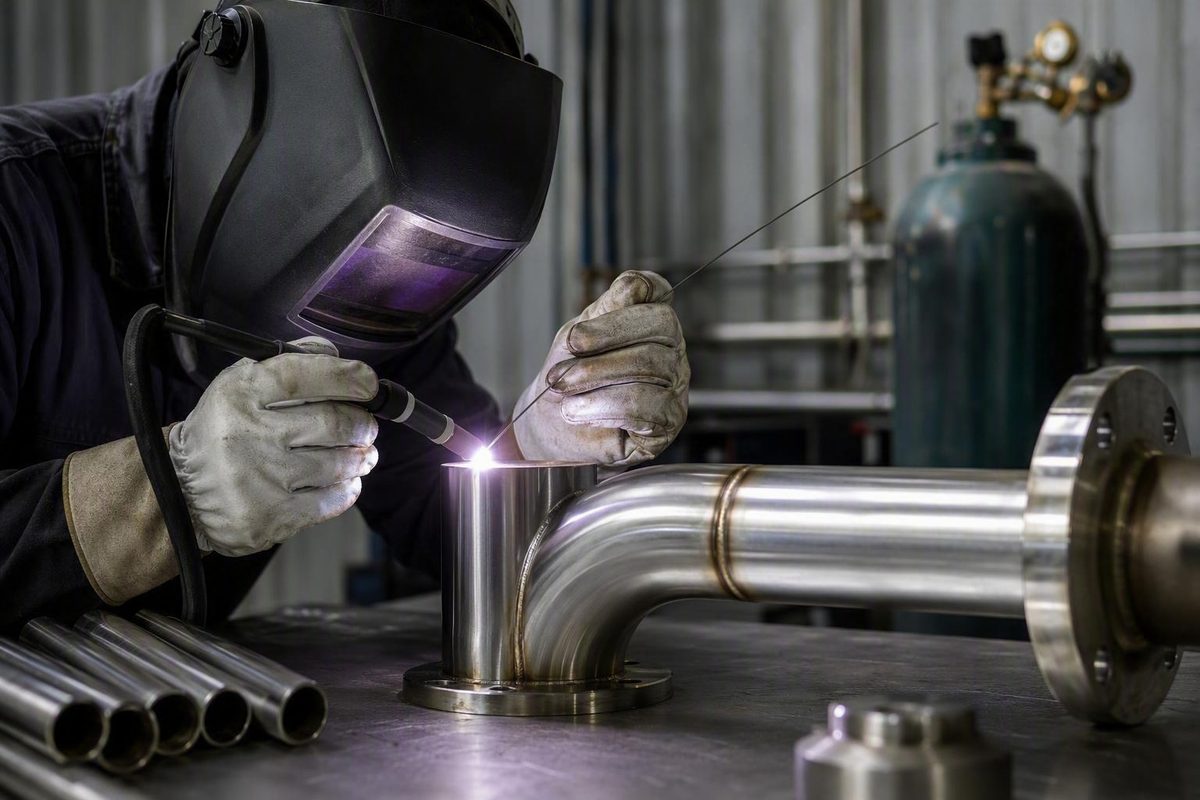
Successful stainless TIG welding depends less on finding one perfect settings chart than on controlling the entire process: alloy identification, cleanliness, fit-up, polarity, tungsten preparation, shielding, filler selection, arc length, travel speed, and protection during cooling.
This guide provides practical starting points for non-code fabrication involving common 300-series austenitic stainless steel, especially 304L and 316L. It is not a universal procedure, a welding procedure specification (WPS), a procedure-qualification guide, an inspection standard, or a corrosion-restoration procedure. Requirements in an applicable WPS, code, drawing, consumable data sheet, equipment manual, customer specification, or site rule take precedence.
When TIG Is the Right Process for Stainless Steel
TIG, formally gas tungsten arc welding (GTAW), creates an arc between a non-consumable tungsten electrode and the workpiece. Inert shielding gas protects the weld area, while filler metal—when required—is fed separately into the puddle.
Because the tungsten, current, and filler addition are controlled independently, TIG gives the welder precise control over a small weld pool. It is especially useful for:
- Thin stainless sheet and tubing
- Small or detailed joints
- Visible welds where bead shape matters
- Joints requiring carefully controlled filler placement
- Short production runs and custom fabrication
- Work where spatter and slag would complicate cleanup
A foot pedal or torch-mounted control can vary current as the part heats. Filler can be added only where needed or omitted in an appropriate autogenous joint. These capabilities make TIG versatile, but they do not make every TIG weld inherently stronger, more corrosion resistant, or more acceptable than a MIG weld. Those outcomes depend on joint design, procedure, consumables, shielding, execution, and inspection.
TIG also has practical disadvantages. Coordinating the torch, filler rod, and current control requires skill, and travel is usually slower than with a continuously fed wire process. A general MIG-versus-TIG comparison from Fractory characterizes TIG as the slower, more precise option and MIG as the faster choice for production runs and thicker fabrication.
Choose MIG when deposition speed, long seams, throughput, or ease of operation matters more than narrow puddle control. Choose TIG when thin material, access, appearance, or precise filler placement makes the slower pace worthwhile. Neither process is best for every job.
The guidance that follows is directed primarily at common 304L and 316L sheet, plate, tube, and pipe. Do not transfer the default recommendations unchanged to duplex, ferritic, martensitic, or precipitation-hardening stainless.
Identify the Material and Joint Before Choosing Settings
Do not identify stainless by appearance alone. Confirm the grade from material markings, purchasing records, drawings, a material test report, or an appropriate identification method. A magnet is not a reliable grade test because cold-worked 304 can develop a magnetic response even though annealed 304 is generally treated as an austenitic grade.
“Stainless steel” covers several alloy families with different welding behavior:
- Austenitic: Common grades include 304, 304L, 316, and 316L. These are the focus of this guide.
General 304L guidance is therefore not a safe substitute for a grade-specific procedure. Even within the austenitic family, service exposure, operating temperature, restraint, and the other base metal can change the appropriate filler and technique.
Before setting the machine, record or confirm:
- Base-metal grade on both sides of the joint
- Material thickness
- Joint type and preparation
- Welding position
- Root opening, land, and overall fit-up
- Required penetration
- Whether the reverse side is accessible
- Whether the root will be exposed in service
- Corrosion, temperature, or dissimilar-metal conditions
- Whether filler is required
- Applicable WPS, drawing, code, or customer specification
- Available torch, cup, gas lens, and remote current control
Thickness alone does not define the heat demand. Butt joints, fillets, outside corners, lap joints, autogenous seams, and open-root joints distribute heat differently.
A tee or fillet joint can draw heat into two members and may need more current than an exposed outside corner of the same nominal thickness. An outside corner can melt rapidly because the arc is concentrated on accessible edges. A tightly fitted autogenous seam may require less energy and a smaller puddle than a joint receiving substantial filler.
Position also changes the usable range. Gaps, mismatched edges, heavy tacks, inconsistent bevels, and restrained assemblies alter how quickly the joint heats, opens, distorts, or burns through.
Machine response matters too. Cup design, tungsten extension, drafts, and torch access also affect shielding.
Every numerical value later in this guide is therefore a starting point. A chart can place the machine in a plausible range; it cannot qualify the weld or account for the complete joint.
Prevent Contamination Before Striking an Arc
Stainless welding begins at the preparation bench. Remove oil, grease, dirt, marking residue, moisture, loose oxides, and embedded debris. Clean both sides of the joint far enough from the seam to include the weld and heat-affected area.
Use a cleaner suited to the contaminant and workplace. Acetone is one example in Atlantic Stainless’s preparation guidance, but it is not the only acceptable cleaner. Follow the product label, safety data sheet, and site requirements, and allow the cleaner to evaporate completely before welding.
Mechanical preparation tools must also be clean. Reserve wire brushes, grinding wheels, flap discs, files, and abrasive pads for stainless work. Tools previously used on carbon steel can transfer iron-rich residue to the stainless surface. That residue can later rust, undermining the reason stainless was selected even when the underlying stainless remains otherwise sound.
Where practical, separate stainless and carbon-steel preparation areas. If full separation is not possible:
- Remove carbon-steel grinding dust before stainless work.
- Cover or clean shared benches.
- Inspect clamps, fixtures, and layout tools.
- Store and label stainless-only abrasives separately.
- Avoid dragging clean material over contaminated surfaces.
- Protect prepared parts from nearby grinding and cutting.
Clean the filler rod as well as the base metal. Rod handled with dirty gloves, left uncovered on a bench, or exposed to moisture can contaminate an otherwise prepared joint. If cleaning is necessary, use an approved product and let the rod dry fully. During welding, keep the hot end within the shielding envelope instead of repeatedly withdrawing it into room air.
Fit-up is part of contamination and heat control. A changing gap forces the welder to alternate between adding heat to bridge an opening and reducing heat to prevent burn-through. Uneven edges move the arc target and make a small, stable puddle difficult to maintain. Correct avoidable fit-up problems before welding rather than relying on filler to hide them.
Pre-weld readiness check
- The alloy is positively identified.
- The joint and nearby surfaces are clean and dry.
- The filler is the correct classification, clean, and dry.
- Brushes and abrasives are reserved for stainless.
- Fit-up is stable and consistent.
- Gas fittings and hoses are sound.
- The work connection is secure.
- The tungsten is freshly prepared and uncontaminated.
- Purge equipment is installed if the root requires protection.
- The applicable procedure and acceptance criteria are available.
Scope reminder: This checklist supports preliminary setup for common non-code 300-series work. It does not establish procedure qualification, inspection requirements, chemical-cleaning methods, or acceptance criteria.
Set Up the TIG Machine, Tungsten, Torch, and Gas
For conventional TIG welding of common 300-series stainless, use direct current electrode negative (DCEN). Physically, this means connecting the TIG torch to the negative terminal and the work lead to the positive terminal.
A DC-only TIG power source is generally sufficient for common stainless work. The AC balance and waveform controls commonly associated with TIG welding aluminum are not normally required.
Use straight argon as the default torch shielding gas. It provides a practical starting point for common stainless sheet, tube, pipe, and plate work. Argon-helium mixtures are contextual options rather than automatic upgrades. Helium can increase heat transfer, penetration, puddle fluidity, and overall heat input, which may help on thicker material but can also make the puddle and distortion more difficult to control.
For DC TIG, pointed lanthanated and ceriated tungsten electrodes are common choices. Match the diameter to the expected current and the electrode manufacturer’s operating range. If a small electrode overheats or becomes unstable near the required current, use a suitable larger diameter rather than forcing the smaller electrode beyond its useful range.
Some industry guidance also mentions thoriated tungsten. Thorium-bearing electrodes are radioactive, so their selection, grinding, handling, storage, and disposal should follow the electrode documentation and the shop’s approved controls rather than generic online instructions. General TIG guidance also cautions that radioactivity depends on the electrode composition, including whether it contains thorium (GoWelding TIG overview).
Prepare tungsten on clean, dedicated grinding equipment. Grind lengthwise, parallel to the electrode axis, and produce a centered, symmetrical point. Follow the electrode and equipment manufacturer’s preparation instructions.
If the tungsten touches the workpiece, filler, or puddle, stop and restore a clean point before continuing. Do not try to weld through obvious tungsten contamination.
As a starting position, hold the torch at roughly 70–80 degrees to the work and the tungsten approximately 1/16–1/8 inch above it, according to Miller’s basic TIG setup guidance. In practice, the more useful objective is a short, consistent arc that preserves access and visibility without touching the puddle.
Pre-flow and post-flow perform different jobs. Pre-flow establishes shielding around the tungsten and start area before the arc forms. Post-flow protects the cooling weld and hot electrode after the arc stops. At the end of a weld, taper the current and keep the cup near the crater while gas continues to flow. Pulling the torch away immediately removes that protection.
Do not choose gas flow from a regulator number alone. Effective coverage depends on:
- Cup diameter
- Standard collet body versus gas lens
- Tungsten extension
- Torch angle and arc length
- Joint exposure or confinement
- Nearby fans, doors, and cross-drafts
- Hose and fitting condition
- Flowmeter behavior
- Whether the hot filler tip stays inside the shielding envelope
Too little flow can expose the puddle. Correct poor coverage by inspecting the complete gas system rather than automatically increasing the flow.
Use Starting Settings as a Framework, Not a Recipe
Important: None of the settings below is a WPS. The values do not control for every alloy, joint, position, fit-up, cup, machine, filler diameter, travel speed, purge arrangement, or acceptance requirement.
The following table reproduces one manufacturer’s illustrative starting values for stainless TIG welding:
| Stainless thickness | Tungsten diameter | Filler | Amperage | Argon flow |
|---|---|---|---|---|
| 1/16 in. | 1/16 in. | ER308L | 60–80 A | 15–20 CFH |
| 1/8 in. | 3/32 in. | ER308L | 120–150 A | 15–20 CFH |
| 1/4 in. | 1/8 in. | ER308L | 180–250 A | 20–25 CFH |
These illustrative parameters from CK Worldwide do not specify joint type, welding position, complete machine configuration, or every alloy variable. They are broad reference ranges, not settings to transfer directly to a production joint.
Another quick estimate is approximately 0.8 amp per thousandth of an inch of stainless thickness. Under that rule, 0.060-inch material would begin near 48 amps before adjustment. The estimate is not bounded to every thickness or joint and should not override puddle behavior. The Weldmonger TIG settings chart presents the rule as a guideline affected by joint type, position, cup, machine, and control method.
A separate commercial guide recommends beginning roughly 10–20% below a comparable mild-steel rule of thumb because stainless retains heat near the weld (YesWelder’s stainless TIG guidance). That approach depends on which mild-steel rule is being used. The apparent conflict is precisely why no thickness formula can determine final amperage by itself.
Use estimates to select a workable maximum, then adjust according to:
- How quickly the puddle establishes
- Whether both joint edges wet in smoothly
- How much filler chills or enlarges the puddle
- Whether the puddle grows as the part heats
- Whether travel remains controlled
- Whether the root responds as required
- Whether distortion accelerates
- Whether the tungsten remains stable
Joint geometry can move the required current substantially. A tee or fillet may require more heat than an exposed outside corner. A beveled plate joint receiving substantial filler needs different settings from an autogenous sheet seam. Vertical welding may use less current because slower travel allows more heat to accumulate.
Match tungsten diameter to actual current demand. Conversely, a small electrode should not be operated beyond its useful capacity. Follow the electrode and power-source manufacturer’s ranges.
Gas-flow recommendations also appear inconsistent until cup size and setup are considered. A 15–20 CFH range is commonly presented as a basic starting or troubleshooting range. Another approach suggests roughly 2–3 CFH per cup-size number and cites 24–36 CFH for a large number 12 cup. Those are not interchangeable prescriptions; the latter values are tied to a large-cup setup, while the appropriate flow still changes with drafts, joint exposure, torch position, and flowmeter behavior.
Start conservatively and test coverage on scrap that duplicates the joint. If the puddle becomes unstable after flow is increased, investigate turbulence, torch distance, drafts, a damaged diffuser, or a leak instead of increasing flow again.
Use weld behavior to adjust current
- If the puddle quickly becomes wider and harder to contain, ease off the remote current, maintain controlled travel, or let the assembly cool naturally.
- If distortion accelerates, reduce accumulated heat through sequencing, shorter segments, improved fit-up, or lower actual output.
- If filler remains proud and the joint edges do not blend, assess whether current is too low, filler is too large, or travel is too fast.
- If the arc becomes erratic, inspect tungsten condition, arc length, shielding, and the welding circuit before changing several settings at once.
- If the tungsten overheats or becomes unstable, verify polarity and electrode diameter.
Where a pedal or torch control is available, set a maximum that allows the puddle to establish promptly without requiring full control travel for the entire weld. One commercial TIG instructor recommends setting the maximum approximately 10–20 amps above the expected requirement and controlling actual output remotely (Pacific Arc TIG guidance). This is an instructor’s practical preference, not a universal rule, and it assumes enough control to prevent an unintended heat spike.
Choose Filler for the Alloy and Service
Filler selection is not a matter of choosing the rod with the highest alloy number. Consider both base metals, dilution from each side, corrosion exposure, operating temperature, joint restraint, required properties, and the governing procedure.
For common work, this matrix provides limited starting matches:
| Base-metal combination | Common starting filler | Important limitation |
|---|---|---|
| 304 or 304L to similar 304-series stainless | ER308L | Verify service and procedure requirements |
| 316 or 316L to similar 316-series stainless | ER316L | Do not assume it is correct for unrelated grades |
| Many 300-series stainless-to-carbon-steel joints | ER309L | Confirm dilution, temperature, and design requirements |
These matches are consistent with the alloy guidance summarized in YesWelder’s stainless TIG guide. That source also lists 308-type filler for grades including 301, 302, 304L, and 321, but its abbreviated table should not be treated as a universal recommendation for every 321 application.
ER316L is not automatically a superior substitute for ER308L merely because 316-series stainless can offer better resistance in some environments. A filler that sounds “more corrosion resistant” can still be inappropriate for the actual base-metal combination, dilution, operating temperature, or qualified procedure.
“Many” does not mean “all.”
For dissimilar-metal, marine, sanitary, pressure, pharmaceutical, high-temperature, or critical-corrosion work, verify filler selection against:
- The WPS and supporting qualification
- Both base-metal specifications
- The filler manufacturer’s classification and data
- Design temperature and service environment
- Required post-weld treatment
- Applicable code or owner specification
Keep filler clean and dry. As a practical starting technique, a rod thinner than the base material can make it easier to add small, repeatable amounts without excessively chilling or overfilling a thin puddle. This is not a fixed requirement; filler diameter depends on joint volume, current, travel speed, and the applicable procedure.
TIG can also be performed without filler. In autogenous welding, prepared edges fuse directly. This may suit some tightly fitted thin seams, but a neat fit alone does not establish that filler may be omitted. Joint design, metallurgy, reinforcement requirements, service, and the governing procedure determine whether autogenous welding is acceptable.
Weld with a Short Arc and Deliberate Heat Control
Once preparation and setup are complete, use a repeatable sequence:
- Confirm DCEN, gas supply, flow, and any purge arrangement.
- Check tungsten condition and work-lead integrity.
- Tack the joint with small, balanced tacks.
- Establish a controlled puddle without unnecessary dwelling.
- Add filler consistently where the joint requires it.
- Maintain a short arc and steady torch angle.
- Coordinate current and travel as the assembly heats.
- Taper current into the ending crater.
- Keep the cup over the weld during post-flow.
- Allow natural cooling unless an approved procedure specifies otherwise.
Stainless retains heat near the weld and expands substantially when heated. As a seam progresses, the current that worked at the start can produce a larger puddle, wider heat-affected area, and more distortion. A pedal or torch control lets the welder reduce actual output as heat accumulates instead of repeatedly stopping or racing ahead of an oversized puddle.
Moving too slowly adds unnecessary heat and can enlarge the puddle until the joint sags or burns through. Moving too quickly is not a cure by itself. If current, arc length, filler addition, and travel are poorly coordinated, excessive speed can leave edges incompletely fused or filler sitting above the joint.
Aim for enough energy to establish and sustain fusion, then move steadily. “Use less heat” should mean avoiding unnecessary accumulated heat—not selecting the lowest current at which the arc will operate. A cold-looking weld with poor edge transition is not improved merely because its heat tint is light.
General heat-management practices include:
- Tight, even fit-up
- Small, balanced tacks
- Tack spacing that stabilizes the joint
- Short weld segments
- Sequencing that balances shrinkage
- Avoiding unnecessary weaving
- Reducing current as the work heats
- Allowing natural cooling between segments where appropriate
These are shop practices, not a qualified distortion-control procedure. Highly restrained or dimensionally critical assemblies may require engineered fixtures, a planned sequence, measured temperature limits, and inspection defined by the WPS or project documents.
Pulsed TIG can help manage average heat input on thin material or joints prone to distortion. Alternating peak and background current may help establish fusion during the peak and advance during the lower-current portion. Pulse can also be misapplied if the selected values interrupt travel or fail to maintain fusion. There is no universal pulse frequency, background percentage, or duty cycle for stainless; establish those values on representative test pieces or use the approved procedure.
At the finish, taper current rather than abruptly stopping a full-current arc and leaving an unfilled crater. Keep the cup close while post-flow protects the hot weld and tungsten. Keep the hot filler tip inside the shielding envelope until it is no longer vulnerable to rapid oxidation.
Use natural cooling as the general starting practice rather than quenching to accelerate production. If a procedure establishes another cooling method, follow that procedure.
Finally, do not confuse a narrow, uniform surface bead with verified soundness. Appearance can reveal process problems, but it cannot by itself confirm root penetration, sidewall fusion, internal discontinuities, mechanical properties, or corrosion performance.
Decide When the Root Needs Back Purging
Back purging shields the reverse side of a joint from atmospheric oxygen while the root is welded and remains hot. Torch gas protects the face; purge gas protects the root.
Purging is particularly important when a full-penetration root must retain a clean surface and corrosion performance, including many:
- Open-root pipe welds
- Full-penetration tube welds
- Sanitary process lines
- Food or pharmaceutical systems
- Corrosion-sensitive piping
- Joints whose reverse side cannot be cleaned afterward
- Plate butt joints with exposed, service-critical roots
An unprotected stainless root can oxidize severely.
Use four questions to decide whether purging is needed:
- Will the joint penetrate fully? A partial-penetration fillet with no exposed reverse-side hot zone differs from an open root.
- Will the root contact the service environment? An internal tube root can be important even when it cannot be seen after assembly.
- Can the root be accessed and restored afterward? Inaccessible oxidation presents different concerns from a surface that can be treated under an approved process.
- What do the WPS and service specification require? Their purge and acceptance requirements override general guidance.
Not every stainless weld requires back purging. Conversely, plate should not be assumed to be exempt. Penetration, reverse-side exposure, cleanability, corrosion requirements, and service matter more than whether the part is called pipe or plate.
A bounded purge workflow is:
- Isolate the region around the root.
- Introduce argon so it can displace the air.
- Provide an appropriate outlet rather than creating an unvented pocket.
- Check dams, seals, hoses, and fittings for leaks or air entry.
- Establish coverage before welding the root.
- Avoid disturbing containment during welding.
- Maintain protection while the root remains hot enough to oxidize.
Appropriate values depend on volume, geometry, leak rate, venting, alloy, procedure, and service. High flow is not a substitute for effective containment and controlled venting.
Critical-work requirement: Pressure, sanitary, food-service, pharmaceutical, and code-regulated welds should follow an approved purge procedure and stated acceptance criteria. Do not qualify a root by appearance alone.
When purging enclosed piping, vessels, or confined spaces, follow the gas-supplier instructions and the site’s ventilation, atmospheric-testing, entry, and work-control requirements.
Diagnose the Weld, Clean It, and Know What Appearance Cannot Prove
Troubleshoot one category at a time. If current, gas flow, cup position, tungsten, and travel speed are all changed simultaneously, the weld may improve without revealing which problem was corrected.
| Symptom | Likely areas to inspect | Immediate correction | Limits of visual diagnosis |
|---|---|---|---|
| Gray, dark blue, purple, or black face | Accumulated heat, slow travel, long arc, poor coverage, drafts, leaks, premature torch removal | Shorten the arc, coordinate current and travel, repair leaks, improve coverage, and maintain post-flow | Color cannot prove fusion, strength, corrosion resistance, or acceptance |
| Porosity | Dirty or wet base metal, contaminated filler, gas leaks, damaged hoses, inadequate or turbulent coverage, contaminated tungsten | Stop, clean and dry the joint and rod, prepare clean tungsten, and inspect the gas system | Surface pores do not reveal the complete internal extent |
| Wobbly or unstable puddle | Excessive flow, long arc, poor tungsten condition, drafts, loose work connection | Correct one variable at a time and restore a short arc and stable gas pattern | A stable-looking puddle does not verify weld soundness |
| Tungsten contamination | Contact with the puddle, filler, or workpiece | Stop and restore clean tungsten | Continuing can spread contamination even if the arc still operates |
| Distortion | Excess current, slow travel, long segments, poor sequencing, inadequate tacking | Reduce accumulated heat, improve fit-up and sequence, and use remote control or suitable pulse | Final dimensions do not reveal internal fusion |
| Burn-through | Gap, edge mismatch, excessive local heat, slow travel | Repair fit-up, reduce actual current, maintain travel, and use small balanced tacks | Closing the opening cosmetically may not restore the joint |
| Poor fusion or proud filler | Insufficient current, excessive filler, fast travel, poor arc placement, unsuitable preparation | Assess current, travel, filler volume, and geometry together | Smooth surface transitions do not prove complete fusion |
| Sugared root | Failed purge, air entry, poor displacement, early purge removal | Restore containment and maintain reverse-side protection through hot cooling | Root appearance must still be judged against governing criteria |
| Cracking | Unsuitable filler, contamination, restraint, crater termination, unsuitable procedure | Stop production and determine the cause before repair | Surface inspection can miss subsurface or delayed cracking |
Discoloration can help diagnose shielding and heat control, but it is only a practical heuristic. One commercial guide describes straw or bright yellow as desirable, light blue as potentially acceptable, dark blue or purple as higher risk, and black as an indication that rework may be necessary. These categories are not universal acceptance limits.
Color varies with alloy, surface finish, thickness, lighting, shielding, heat history, and service requirements. A gold bead is not automatically acceptable, and a blue bead is not automatically rejectable. Color alone cannot establish:
- Penetration
- Sidewall or root fusion
- Internal porosity
- Mechanical strength
- Corrosion performance
- Chemical cleanliness
- Code compliance
For a dark or gray weld, inspect the complete shielding system before blaming amperage alone. Check arc length, torch angle, cup distance, gas-lens condition, flow, leaks, drafts, post-flow, and whether the torch was removed while the weld was still hot. Then examine actual current and travel speed.
For porosity, return to cleanliness and gas integrity. Confirm that the base metal and filler are dry, the tungsten is clean, hoses are undamaged, fittings are secure, and gas reaches the cup. Excessive flow can entrain surrounding air, so maximizing the regulator is not a reliable correction.
For an unstable puddle, verify tungsten condition, work connection, arc length, shielding pattern, and nearby air movement. If instability began after increasing gas flow, reduce it and reassess rather than assuming more gas must be better.
If the tungsten touches anything in the weld zone, stop and restore a clean electrode. Trying to continue sacrifices arc stability and process control.
For distortion or burn-through, look beyond the amperage display. Correct gaps and edge mismatch, use balanced tacks, shorten the weld sequence, reduce current as the assembly heats, and coordinate travel. Pulse may help where suitable, but it cannot compensate for poor fit-up or an oversized puddle.
For poor fusion, do not reflexively reduce current because the bead has color. Examine joint mass, preparation, filler diameter and volume, travel speed, arc placement, and actual current together. Heat control means supplying the energy required for fusion without unnecessary accumulation.
For sugaring, inspect reverse-side containment, leaks, venting, air displacement, and how long protection remained in place during cooling. Increasing purge flow alone will not necessarily correct a leaking or poorly arranged enclosure.
Address heat tint and oxide according to the service requirements. Mechanical cleaning may improve appearance, but appearance alone does not establish that critical corrosion performance has been restored. If pickling, passivation, or another chemical treatment is specified, follow the approved procedure, product label, safety data sheet, and site controls. Do not improvise chemical cleaning from generic advice.
Final safety check
- Wear the PPE required for the process and workplace.
- Use the ventilation and fume controls specified by the site.
- Protect nearby personnel from arc exposure and hot-work hazards.
- Inspect electrical leads, torch components, and connections.
- Follow cleaner labels and safety data sheets, and allow cleaners to evaporate fully.
- Use approved controls for grinding dust and electrode materials.
- Follow gas-supplier and site requirements for purge operations.
- Apply confined-space and hot-work procedures where required.
- Identify and isolate hot metal.
- Follow the machine manual, WPS, product documentation, and site rules.
Welding involves electrical current, fumes, ultraviolet exposure, heat, and other hazards. Equipment instructions and site rules override general article guidance, as also stated in Welder Facts’ safety terms.
Frequently Asked Questions
Can I TIG weld stainless steel with a DC-only welder?
Yes. A DC-only TIG welder is generally sufficient for conventional TIG welding of common 300-series stainless. Use DCEN: connect the torch to negative and the work lead to positive.
You do not normally need the AC balance and cleaning controls associated with TIG welding aluminum. You still need sufficient output for the material and joint, a sound gas system, an appropriate torch and tungsten, and a secure work connection. Follow the machine manual for terminal selection, gas control, duty cycle, and remote-control setup.
Should TIG welding stainless use pure argon or an argon-helium blend?
Use straight argon as the default for common stainless fabrication. It is a practical starting gas for sheet, tubing, pipe, and moderate plate work.
An argon-helium blend may be useful when thicker material or joint geometry calls for greater heat transfer and penetration. The tradeoff is that added heat can enlarge the puddle and increase distortion risk. Before changing gas, verify that joint preparation, amperage, arc length, travel, and fit-up are not the actual limitations.
Gas composition and flow are separate decisions. Even with straight argon, coverage depends on cup diameter, gas-lens design, tungsten extension, joint exposure, leaks, and drafts.
What filler rod should I use for 304L, 316L, or stainless-to-carbon steel?
ER308L is a common starting filler for 304L and related 304-series stainless. ER316L is a common starting match for 316L. ER309L is commonly used for many stainless-to-carbon-steel joints.
These are starting matches, not universal selections. Check both base metals, dilution, service temperature, corrosion exposure, joint restraint, and the WPS. Do not substitute ER316L merely because it sounds more corrosion resistant. Critical dissimilar-metal, pressure, sanitary, marine, and high-temperature joints require procedure or filler-manufacturer verification.
When does a stainless TIG weld need back purging?
Back purge when a full-penetration root requires protection from atmospheric oxidation, especially in open-root pipe, tubing, sanitary work, corrosion-sensitive systems, and joints whose reverse side cannot be cleaned afterward.
Base the decision on penetration, root exposure, cleanability, service, and the governing procedure—not simply on whether the workpiece is pipe or plate. Some plate butt joints need reverse-side protection, while many non-penetrating stainless welds do not.
Maintain protection while the root remains hot enough to oxidize. Use the approved procedure for flow, displacement, oxygen limits, dams, duration, and acceptance.
What do blue, purple, gray, or black colors on a stainless weld mean?
These colors indicate differing levels of surface oxidation and can point to excessive accumulated heat, slow travel, a long arc, poor shielding, leaks, drafts, inadequate post-flow, or moving the torch away too soon.
Straw or bright yellow is often treated as a favorable practical indicator. Light blue may be tolerated in some noncritical work, while darker blue, purple, gray, or black generally warrants closer investigation. There is no universal color rule across every alloy, application, or industry.
Color cannot prove penetration, fusion, mechanical integrity, corrosion resistance, or code compliance. Correct the process and then apply the inspection and acceptance criteria required for the job.
Before the next stainless TIG weld, use a compact workflow: verify the alloy and procedure; remove contamination; establish stable fit-up; set DCEN and straight argon; prepare clean, pointed tungsten; select filler for the actual base metals and service; begin with conservative settings; maintain a short arc and steady travel; protect any corrosion-sensitive root; and hold shielding over the weld as it cools.
Settings charts and bead color are diagnostic starting points—not substitutes for a WPS, inspection, equipment instructions, or applicable acceptance criteria.