
How to Stick-Weld Stainless Without Guessing at the Setup
MMA is usually more practical on medium or thicker stainless; very thin material is more likely to suit TIG or a controlled MIG process.
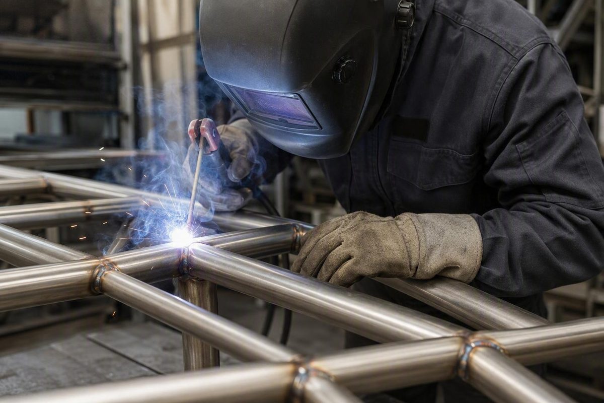
Can You Weld Stainless Steel With MMA?
Yes. A conventional MMA welder can weld stainless steel when the electrode, polarity, joint design, technique, and procedure suit the identified base metals and intended service.
MMA, stick welding, and shielded metal arc welding—SMAW—are names for the same process. An arc forms between the workpiece and a consumable, flux-coated electrode, melting the electrode core and base metal into a weld pool. The flux supplies shielding and then forms slag that must be removed after welding. ESAB explains the process and the role of polarity in stick welding.
Because shielding comes from the electrode coating, MMA does not require an external shielding-gas cylinder at the arc. A power source, leads, electrode holder, work clamp, and suitable electrodes can be carried into locations where moving a TIG or MIG package would be inconvenient. MMA is also less vulnerable than an externally gas-shielded process to wind disrupting the shielding.
That makes MMA useful for:
- Outdoor maintenance and field repairs
- Restricted-access joints where a torch or wire feeder is awkward
- Mobile work where shielding-gas equipment would be burdensome
- Medium or thicker stainless sections
- Short repairs where production speed is secondary
- Some stainless-to-carbon-steel joints, provided the filler is correctly selected
The tradeoffs are significant. Electrodes must be replaced as they are consumed, every pass leaves slag, and deposition is discontinuous. The puddle is generally less controllable than a TIG puddle, especially on thin stainless or joints with inconsistent gaps. MMA is therefore usually more practical on medium or thicker material, while very thin material is more likely to suit TIG or a controlled MIG process.
There is no universal minimum thickness for stainless SMAW. Electrode diameter, joint type, fit-up, welding position, machine response, and operator skill all affect the margin between fusion and burn-through. Claims that stainless below one particular thickness is either always weldable or categorically impossible with MMA are too broad.
TIG or suitably controlled MIG is often preferable when:
- The material is thin sheet
- Distortion must be minimized
- Bead appearance is important
- Filler addition requires close control
- Slag or extensive finishing is unacceptable
- The joint has demanding corrosion or cleanliness requirements
- Consistent production speed matters
TIG provides close control over the arc and filler addition. MIG offers continuous deposition and can improve productivity when the joint, equipment, shielding, and procedure are suitable. Neither is automatically better in every setting: portability, access, and outdoor conditions may still make MMA the practical field process.
Before choosing MMA, ask:
- Thickness: Is there enough material and fit-up control to tolerate the stick-welding arc?
- Access: Can the electrode be held at a stable angle as it shortens?
- Environment: Would wind make external gas shielding unreliable?
- Finish: Are slag removal and post-weld blending acceptable?
- Position: Is the complete electrode classification approved for the required position?
- Service: Will the joint face corrosive exposure, elevated temperature, pressure, fatigue, or hygiene requirements?
- Procedure: Is the work controlled by a welding procedure specification, code, drawing, or client instruction?
If a qualified procedure governs the job, it controls the work. A general guide cannot replace its material, consumable, parameter, qualification, or inspection requirements.
Choose the Electrode From Both Base Metals
Do not choose a stainless electrode by looking at only one side of the joint. Use this sequence:
- Identify the grade and condition of both base metals.
- Determine whether the joint is stainless-to-stainless or stainless-to-carbon steel.
- Establish the service environment and required properties.
- Check the drawing, WPS, code, or repair instruction.
- Select a possible electrode family.
- Verify the full classification, manufacturer, diameter, approved positions, polarity, and operating range.
Three electrode families commonly appear in austenitic stainless work:
| Common joint | Common starting electrode | Required verification |
|---|---|---|
| 304 or 304L to compatible 304-series stainless | E308L | Exact grades, required properties, full suffix, position, polarity, and WPS |
| 316L to compatible 316 or 316L stainless | E316L | Service exposure, full suffix, position, polarity, and procedure |
| Common austenitic stainless to carbon or mild steel | E309L | Both alloys, dilution, strength, corrosion exposure, temperature, restraint, and procedure |
E308L is a common starting family for many compatible 304- and 304L-type applications. It is not automatically correct for every alloy with a 300-series designation. E316L is a common starting match for compatible 316 and 316L joints, subject to service and procedure requirements. E309L is frequently used for common stainless-to-carbon-steel combinations, but it is not a universal rod for unidentified steels. These common starting matches are summarized in YesWelder’s guide to stainless SMAW electrodes.
The L designation alone does not establish that the finished weld will satisfy a particular corrosion requirement. Filler selection can also depend on:
- Dilution from both base metals
- Required tensile, impact, or fatigue performance
- Corrosive or high-temperature exposure
- Joint restraint and cracking risk
- Weld-metal ferrite requirements
- Required thermal treatment
- Compatibility with subsequent finishing
- The applicable code and qualified WPS
Stop guessing if either material cannot be positively identified.
These families can require alloy-specific filler and thermal controls. The same caution applies to pressure equipment, structural connections, sanitary systems, corrosion-critical plant, and components whose failure could injure someone.
For a noncritical repair without a formal procedure, treat E308L, E316L, or E309L only as a possible starting family. Confirm the choice against reliable material identification and the exact electrode manufacturer’s literature before welding.
Read the Full Electrode Classification Before Setting the Machine
“E308L” or “E309L” is not enough information to set the welder. The complete classification—including a suffix such as -15, -16, or -17—and the manufacturer’s product data can affect:
- Permitted current type and polarity
- Approved welding positions
- Diameter-specific current range
- Arc starting and stability
- Slag volume and release
- Puddle fluidity
- Toe wetting
- Bead contour
- Storage and conditioning requirements
As broad tendencies, -15 stainless electrodes are commonly associated with lime-type coatings and DCEP operation. -16 products are commonly associated with titania coatings and may run on specified AC or DCEP equipment. -17 products are commonly associated with silica-titania characteristics, good wetting, and flatter bead profiles. These are orientation points—not a universal polarity or position table.
Generic guidance about positional capability is inconsistent. Some guides describe -16 products mainly in connection with flat and horizontal welding. In a product-specific comparison, however, the tested 309L-16 electrode was more controllable uphill than the tested 309L-17, while the -17 produced a wetter, flatter puddle that the presenter found difficult to manage vertically. The Weld.com 309L-16 versus 309L-17 demonstration illustrates how coating behavior can affect the puddle, but its settings and operator results are not transferable procedure values.
Resolve such conflicts by checking the exact package or manufacturer data sheet. Verify:
- Full electrode classification
- Product name and manufacturer
- Electrode diameter
- Approved positions
- Permitted DCEP, DCEN, or AC operation
- Current range for the diameter and position
- Storage and atmospheric-exposure requirements
- Manufacturer-approved conditioning instructions
DCEP—direct current electrode positive—is common for many stainless stick electrodes, but it is not universal. Do not choose AC merely because the machine provides it, and do not use DCEN as a shortcut for reducing heat unless the exact electrode permits it. Incorrect polarity can produce difficult starts, an unstable arc, excessive spatter, unexpected or inadequate penetration, and poor puddle control.
There is also no dependable universal thickness-to-amperage chart for stainless SMAW. A chart that omits the manufacturer, complete classification, electrode diameter, joint geometry, position, travel speed, and machine behavior omits too much to function as a procedure. Amperage charts for mild-steel electrodes such as E6013, E7016, or E7018 should not be transferred directly to stainless consumables.
Use this setting method instead:
- Find the manufacturer’s approved range for the exact product and diameter.
- Confirm that the selected polarity and welding position are permitted.
- Choose a starting current within that range.
- Reproduce the joint and fit-up on matching scrap.
- Assess arc starting, stability, puddle control, fusion, toe wetting, crown, spatter, and slag behavior.
- Adjust one variable at a time in small increments.
- Use the inspection or testing method required by the job rather than inventing an informal acceptance test.
Out-of-position work often benefits from a smaller electrode or lower current than the same joint in the flat position. That does not mean reducing current until the rod continually sticks or fusion disappears. Stay within the product’s approved range and preserve adequate fusion.
Prepare the Stainless, Joint, Electrodes, and Welding Circuit
MMA may be relatively tolerant of field conditions, but stainless preparation still matters—especially when the finished component depends on corrosion resistance, cleanliness, or an uncontaminated surface.
Use this preparation checklist:
- Identify both base-metal grades.
- Confirm the electrode family and complete classification.
- Review the product data sheet and applicable WPS.
- Verify thickness, joint type, root condition, and required penetration.
- Check fit-up and alignment.
- Remove oil, grease, moisture, grime, oxides, paint, and embedded debris.
- Prepare matching scrap with representative fit-up.
- Confirm that the intended welding position is approved.
- Inspect the machine, holder, leads, connectors, and work clamp.
Use wire brushes, grinding discs, flap wheels, files, and other abrasives reserved for stainless steel. Tools previously used on carbon steel can transfer ferrous particles onto stainless. Those particles can later rust and stain the surface. Dedicated stainless tooling is a standard precaution in practical stainless stick-welding preparation guidance.
Keep the surrounding work area clean as well. A new stainless brush offers little protection if carbon-steel grinding dust settles over the joint afterward. Clean the groove, adjacent surfaces, tack locations, and contact areas for fixtures or backing.
Plan clamps and tacks to preserve alignment without creating unnecessary restraint. Stainless expands under localized heating, and a long seam can pull or bow as heat accumulates. Balanced tacking, a suitable welding sequence, and supportive fixtures can reduce movement. Fixturing should suit the joint and procedure rather than rigidly locking every edge by default.
For thicker plate or pipe, use the specified bevel, root opening, backing arrangement, and pass sequence. Multiple controlled passes are generally preferable to forcing a large joint with an oversized electrode and excessive current. Exact groove dimensions, root technique, and backing requirements belong in the WPS or engineering instruction.
A backing or chill bar may help support the root or manage heat when the joint design and procedure permit it. It should not be treated as a universal requirement. Defer material choice, placement, and any backside protection to the applicable procedure.
Electrodes must be dry, clean, and mechanically sound. Reject rods with cracked, chipped, contaminated, or badly eccentric coatings. Do not invent rod-oven temperatures or rebaking cycles: storage temperatures, exposure limits, and conditioning instructions vary by product and must come from its manufacturer.
The welding circuit matters as much as electrode condition. Attach the work clamp to clean, bare metal as close to the work as practical. Ensure that leads and connectors are tight and undamaged.
Before striking the arc, stop and confirm:
- Required PPE is in place.
- Ventilation or source capture is operating as required.
- Site hot-work and fire-control requirements have been met.
- The working area is clean and dry.
- Polarity is correct.
- Current is within the electrode’s approved range.
- The electrode coating is sound.
- Preparation tools are reserved for stainless.
- Fit-up is secure and suitable.
- The work-clamp connection is clean and sound.
- Representative scrap is ready for the test bead.
Control Heat With a Short Arc and Small, Deliberate Passes
Stainless behaves differently from mild steel under the arc. Heat remains concentrated around the weld zone while thermal expansion moves the joint. Practical consequences can include burn-through, distortion, cracking, discoloration, and difficulty preserving the intended surface and corrosion performance.
Heat management is not simply an amperage setting. It combines current, arc length, bead size, travel speed, sequence, and cooling time.
Begin with the lowest practical current that still provides stable operation and adequate fusion. “Lowest practical” does not mean turning the machine down until the electrode repeatedly sticks. If the puddle will not tie into the toes or slag crowds the arc because the metal is not flowing properly, further current reduction is unlikely to help.
Keep a consistently short arc. The goal is a stable arc close to the puddle without burying the coating or repeatedly shorting the rod.
Use narrow stringer beads as the default starting technique. If the qualified procedure specifies a particular weave, bead width, or manipulation pattern, follow it.
On a long seam, divide the weld into manageable sections and use a planned sequence. Alternating locations or using a backstep approach may reduce cumulative pulling in one direction when appropriate for the joint. Do not copy an arbitrary pass length as a qualified value; part stiffness, thickness, tack layout, joint design, and access all affect the result.
Travel speed must balance fusion against heat accumulation:
- Too slow: The puddle grows, discoloration expands, and burn-through or distortion becomes more likely.
- Too fast: The bead may become narrow or excessively convex, with poor toe tie-in or incomplete fusion.
- Too much dwell at the sides: Heat and slag can accumulate at the toes.
- Too little controlled pause where needed: The weld may bridge the joint without fusing its edges.
A small drag angle may work with many stainless electrodes, but any proposed angle is a starting technique to test—not a universal procedure value. Coating behavior changes the useful angle and how the slag follows the puddle.
Allow natural cooling between passes unless the procedure specifies preheat, an interpass range, or another thermal treatment. Do not improvise quenching or cooling methods. Specialized stainless families can have explicit thermal requirements, so “keep it cold” is not a substitute for alloy-specific instructions.
Do not approve a weld by appearance alone. Acceptance and inspection must follow the service requirements and governing procedure.
Adjust the Technique for Flat, Horizontal, Vertical-Up, and Overhead Work
An electrode that runs smoothly in the flat position can become difficult when the work rotates. Gravity changes how molten metal and slag move, so horizontal, vertical, and overhead welding require a smaller, more controlled puddle.
Flat welding
Use the flat position to learn the exact electrode before attempting a critical out-of-position joint. Establish a short, stable arc and observe:
- How quickly slag forms
- Whether slag remains behind the puddle
- How readily the metal wets into both toes
- How much crown the electrode naturally produces
- Whether slag releases cleanly after cooling
- How small current changes affect fusion and fluidity
A good-looking flat bead does not prove the same setting will work vertically. Flat welding can support a larger, more fluid pool, so a comfortable flat setting may be excessive out of position.
Horizontal fillets
In a horizontal fillet, the weld pool and slag tend to move toward the lower plate. Keep the bead small enough for the joint to support. Use conservative heat, a tight arc, and deliberate placement at the upper toe so the weld does not simply wash downward.
Watch the boundary between slag and weld metal. If slag moves ahead of the arc, blindly increasing travel speed may make tie-in worse. Reassess electrode angle, current, bead size, and whether the exact product is approved and controllable in that position.
Vertical-up welding
First confirm that the exact electrode is approved for vertical-up welding. Consider a smaller diameter where practical, and reduce a flat-position setting if it creates an unmanageable pool—while remaining within the product’s approved range.
Hold a tight arc and use restrained manipulation. The purpose of a slight step, triangle, or side-to-side motion is to establish fusion and support the puddle, not to draw a large pattern. Excessive weaving can let slag collect at the sides or run below the arc.
Product behavior matters. In the Weld.com comparison, the tested 309L-17 produced a wetter, flatter pool but was difficult for the presenter to control uphill. The tested 309L-16 was more controllable uphill and produced a more crowned bead. That observation illustrates the importance of the suffix and coating; it does not establish universal positional capability or transferable machine settings.
A Miller forum discussion about vertical stainless stick welding contains widely differing user-reported settings for nominally similar electrodes. Because the exact manufacturers, classifications, joints, and material dimensions were not established, those reports should be treated only as anecdotal troubleshooting leads—not authoritative recommendations.
Overhead welding
Overhead stainless SMAW requires an electrode approved for the position, a short arc, and a puddle small enough to remain controllable. Follow the applicable PPE and site-safety requirements for overhead hot work, where slag and molten material can fall toward the operator.
Remove slag completely before adding another pass. Examine the toes and transitions under good lighting; slag can hide incomplete tie-in, undercut, or trapped material.
For every position, practice on matching scrap before welding the actual component. After cleaning the practice bead, check for:
- Surface porosity or pinholes
- Trapped slag
- Undercut
- Excessive crown
- Poor toe wetting
- Incomplete tie-in
- Irregular bead width
- Signs that the puddle repeatedly ran ahead of the arc
If the test remains uncontrollable, do not force the joint. Verify classification and polarity, change electrode diameter, improve fit-up or access, or select a more controllable process.
Troubleshoot the Weld by Symptom, Not by Amperage Alone
Amperage is only one variable. When a defect appears, identify the plausible causes before turning the current knob.
| Visible symptom | Likely checks | Cautious correction |
|---|---|---|
| Porosity or pinholes | Oil, moisture, oxides, electrode condition, coating damage, long arc, wrong polarity, unstable shielding, contaminated tools | Clean again, replace questionable rods, shorten the arc, verify polarity and operating range, then retest |
| Slag inclusions | Incomplete interpass cleaning, excessive weaving, poor placement, slag running ahead, low current, awkward angle | Remove all slag, narrow the bead, correct placement and angle, verify current, and revise the pass sequence |
| Excessive crown | Poor wetting, low current, fast travel, long arc, coating behavior in the position | Confirm product and position, shorten the arc, and adjust current or travel incrementally |
| Burn-through or broad discoloration | Excessive current, oversized electrode, slow travel, long dwell, wide gap, poor fit-up, thin material | Improve fit-up, use a smaller approved rod, shorten dwell, reduce heat within the approved range, or change process |
| Distortion | Large passes, continuous seams, weak tacking, poor sequence, insufficient cooling | Use smaller passes, improve tacking and sequence, alternate locations where appropriate, and allow cooling |
| Unstable arc or heavy spatter | Wrong polarity, poor clamp contact, damaged leads, dirty surface, long arc, damaged electrode, operation outside the approved range | Verify the circuit and polarity, clean the clamp location, inspect leads and rods, shorten the arc, and reset within product data |
| Poor fusion | Contamination, inadequate preparation, low current, excessive travel speed, poor angle, poor access, unsuitable process | Reprepare the joint, correct angle and travel, restore adequate current, and reconsider whether MMA suits the joint |
| Undercut or poor toe tie-in | Excessive current, long arc, fast travel, poor placement, oversized puddle | Tighten the arc, reduce puddle size, improve placement, and adjust current and travel together |
| Electrode sticking | Low current, poor starting technique, weak circuit, wrong polarity, damaged coating | Check the circuit and product requirements, replace suspect rods, and increase current only within the approved range |
For porosity, do not begin by increasing current. Check surface contamination, electrode condition, polarity, arc length, and circuit stability first. If the coating is damaged or improperly stored, amperage cannot restore it.
For slag inclusions, clean to visible weld metal after every pass. Pay particular attention to toes, craters, and transitions between beads. Do not cover residual slag simply because most of the bead centerline appears clean.
Treat the shape as a clue, then change one variable at a time on scrap.
Burn-through and broad discoloration indicate that the heat balance needs attention, but the correction is not always lower current. A wide gap, oversized electrode, slow travel, or unsuitable process can produce the same symptom. If reducing current causes sticking and poor fusion, MMA may not provide a workable operating window.
Poor fusion deserves particular caution. Do not sacrifice fusion solely to keep the stainless visually cool. Reassess cleaning, groove preparation, access, angle, travel speed, electrode size, and current. If adequate fusion cannot be achieved while retaining control, change the setup or process.
Recurring defects on structural, pressure, sanitary, lifting, transportation, or other safety-critical work are a stop signal. Obtain the qualified procedure and required inspection instead of repeatedly grinding and rewelding without identifying the cause.
Clean the Weld, Control Fumes, and Know When to Change Processes
Remove slag completely after every pass and after the final weld. Use stainless-dedicated tools so post-weld cleaning does not reintroduce ferrous contamination. Clean around the toes, starts, stops, and craters—not just the center of the bead.
Several post-weld terms are often treated as if they mean the same thing, but they do not:
- Slag removal clears the solidified electrode-flux residue.
- Surface cleaning removes loose contamination and welding residue.
- Heat-tint or oxide removal addresses oxidized surface layers.
Do not improvise chemical mixtures or procedures. If chemical treatment is required, follow the approved service specification, product safety information, and site controls for handling, ventilation, storage, and disposal.
Discoloration shows that oxidation and heat exposure occurred, but color alone is not a universal acceptance standard. Acceptability depends on the alloy, service, surface specification, and required post-weld treatment.
Stainless-welding fumes can present serious health risks. Use the ventilation, local exhaust or source capture, PPE, and respiratory controls selected through the applicable exposure assessment and site safety program. General stainless-welding safety guidance from R-Tech emphasizes fume control and suitable protection, but equipment instructions and formal workplace requirements must determine the actual controls.
Other welding hazards remain, including current, arc radiation, hot material, fire, and grinding operations. Follow the equipment manual, hot-work system, site rules, and applicable safety program. This article is informational and does not replace those requirements; the site’s editorial safety notice likewise places equipment manuals and site rules above general article guidance.
Before committing to MMA, make one final process decision.
Favor TIG or controlled MIG when:
- The stainless is very thin
- Fit-up is delicate or gaps vary
- Distortion must be minimized
- Appearance is critical
- Slag cannot be tolerated
- Production speed matters
- The root or backside requires precise control
Favor MMA when:
- Portability is a priority
- Outdoor conditions make external gas shielding impractical
- Access is restricted
- The material provides a manageable operating window
- The job is a short field repair
- Shielding-gas equipment is unavailable
- Slag removal and additional finishing are acceptable
The practical decision sequence is compact: identify both metals, select an electrode family only as a starting point, verify the full classification and manufacturer data, clean with stainless-dedicated tools, test on matching scrap, weld with a short arc and controlled heat, and remove slag completely.
MMA is valuable for portable repair and field fabrication. It should not become a reason to persist with an unsuitable setup. When the material is thin or the job demands exceptional control, finish, productivity, or corrosion performance, changing to TIG or MIG may be the better decision. Equipment manuals, electrode data sheets, qualified procedures, governing codes, and site rules always override generic online guidance.
Frequently Asked Questions
Can a normal MMA or stick welder weld stainless steel?
Yes, provided the machine can supply the polarity and current required by a suitable stainless electrode. The joint must be properly prepared, and the electrode must suit the identified base metals, welding position, and service.
A machine being “stick capable” does not make every stainless electrode compatible with it. Check whether the exact rod requires DCEP or permits AC or DCEN, then confirm that the machine can deliver stable output within the manufacturer’s range.
Which MMA electrode is commonly used for 304 or 316 stainless steel?
E308L is a common starting family for many compatible 304- and 304L-type joints. E316L is a common starting match for compatible 316 and 316L joints.
Neither choice is automatic. Confirm both base metals, the full electrode suffix, service environment, required properties, welding position, polarity, and governing procedure.
What rod should I use to MMA weld stainless steel to mild steel?
E309L is a frequent starting choice for common austenitic stainless-to-mild-steel or stainless-to-carbon-steel joints. Suitability still depends on the exact alloys, dilution, required strength, corrosion exposure, operating temperature, restraint, and applicable procedure.
Do not treat E309L as a universal solution for unknown steel. Identify both materials or obtain an approved repair instruction before welding.
Should stainless stick electrodes run on DCEP, DCEN, or AC?
Many stainless stick electrodes commonly run on DCEP, but the exact package or manufacturer data sheet controls. Some products permit AC. Use DCEN only when the exact electrode manufacturer expressly allows it.
Wrong polarity can cause unstable operation, excessive spatter, poor or unexpected penetration, and difficult puddle control. Verify the complete electrode classification before connecting the holder and work lead.
Can thin stainless sheet be welded successfully with MMA?
Sometimes—but thin stainless gives MMA a narrow margin between poor fusion and burn-through. Electrode diameter, fit-up, joint design, position, machine response, and operator control all affect what is practical, so there is no universal thickness cutoff.
For very thin sheet, appearance-critical work, or joints requiring minimal distortion, TIG or a suitably controlled MIG process will often provide a more manageable and repeatable solution.