
How to Build a Dependable Welding-Current Return Path
A clean table stud cannot overcome coated fixture faces, loosely nested components or an isolated subassembly. The path also includes the cable and terminal.
By Cole Brandt, CWI-certified welder | Published August 6, 2026 | Corrections: editor@welderfacts.com
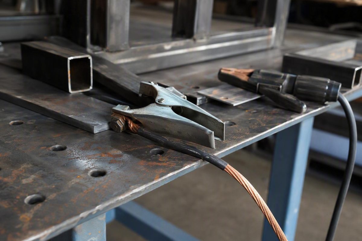
The part commonly called a welding ground or ground clamp is usually the work-return connection. It completes the welding-current circuit between the workpiece and the power source. That function is different from protective grounding of the welding machine’s enclosure.
A dependable return path is more than a clamp attached to nearby metal. It includes the contact point, connector, cable, lug, terminal, fixtures, workpiece, and every interface through which welding current must pass.
What a Welding Ground Is—and What It Is Not
“Ground clamp” remains the familiar retail and shop-floor term. Technically, work clamp, work lead, or work-return connection is more precise. The work connection carries welding current from the workpiece back to the power source; it should not be confused with the protective grounding system for the machine enclosure.
The welding-current loop can be visualized as follows:
Power-source output terminal
        ↓
Electrode lead or gun cable
        ↓
Electrode holder, torch, or welding gun
        ↓
Arc
        ↓
Workpiece
        ↓
Work clamp or other work connector
        ↓
Work lead
        ↓
Power-source return terminal
Depending on the process and polarity, conventional current may be described in the opposite direction. The practical point is the same: the electrode side and work side form one complete welding circuit.
Three concepts must remain separate:
- The welding-current work connection. This is the clamp, magnetic connector, bolted point, rotary connector, or table connection attached to the work lead.
- Protective grounding of the welding-machine enclosure. This is part of the supply-side electrical protection provided for the machine according to its design and installation.
- Any separately required grounding or bonding of the workpiece, table, generator, or supporting structure. Requirements depend on the equipment, installation, jurisdiction, current rules, and approved procedures.
A properly connected work clamp does not make an electrode, wire, contact tip, holder, torch, internal terminal, or other energized part safe to touch. Conversely, protective grounding of the enclosure cannot compensate for a loose work clamp or damaged work cable. Contact with electrically live parts of a welding circuit can be fatal, and proper grounding does not eliminate that risk according to CCOHS electrical-safety guidance.
Terminology matters during troubleshooting. If every connection is called “the ground,” a welder may inspect the work clamp while overlooking a supply-grounding defect—or assume that the protective grounding conductor is intended to carry normal welding current. Treat each circuit according to its actual function.
Why the Work-Return Connection Matters
Welding current requires a continuous path from the workpiece back to the power source. Resistance or a discontinuity anywhere in that path can interfere with reliable current delivery.
Common trouble points include:
- Paint, primer, powder coating, or other nonconductive finishes
- Rust, mill scale, oxide, or surface contamination
- Oil, grease, moisture, slag, or embedded shop debris
- A clamp touching at only a small point
- Weak springs, worn jaws, or damaged contact faces
- Loose studs, bolts, lugs, or machine terminals
- Corrosion inside a cable termination
- Broken or heat-damaged conductor strands
- Unsuitable cable for the machine or workload
- Current paths that depend on loose fixtures, hinges, tacks, or assembled joints
Resistance concentrated at a connection can create localized heating. If a connector, lug, cable end, contact point, or machine terminal becomes unexpectedly hot, stop welding and inspect the system under the shutdown and isolation procedure required by the equipment and workplace. Do not simply install a larger clamp without finding the restriction.
Possible warning signs include:
- Difficult or inconsistent arc starts
- Intermittent current
- Unstable arc behavior
- Visible arcing beneath the connector
- Unexplained heating at a clamp, lug, or terminal
Commercial welding guidance identifies dirty surfaces, loose contact, worn jaws, damaged conductor strands, and unsuitable cable as possible return-path problems worth checking when these symptoms appear.
Other symptoms may occur alongside a poor work connection, but they are not diagnostic by themselves:
- Increased or irregular spatter
- Changes in penetration
- MIG wire burnback
- Stick electrodes tending to stick
- Inconsistent bead appearance
- Output that seems weaker than expected
Settings, polarity, consumables, shielding-gas problems, wire feeding, technique, machine condition, joint preparation, and magnetic arc behavior can produce similar symptoms. Treat an improvement after reseating the clamp as a reason to inspect the return path—not as proof that the clamp caused every prior defect.
Inspect the whole path. A new connector cannot repair damaged cable strands. A large cable cannot compensate for a loose stud. A clean table connection does not guarantee continuity through a painted fixture. A high-amperage clamp cannot make a lightly touching jaw dependable.
How to Make a Dependable Work Connection
When practical, attach the work connector directly to the workpiece at a clean, conductive location. Remove paint, heavy scale, rust, oil, oxide, and other contamination where the drawing, procedure, material, and finish requirements permit.
“Clean metal” does not mean grinding every workpiece indiscriminately. Coated, finished, appearance-critical, pressure-containing, fatigue-sensitive, or metallurgically controlled work may restrict surface preparation and connector placement. Use an approved designated point, sacrificial tab, fixture, or other engineered method rather than damaging the surface or creating an unauthorized arc mark.
Position the connection reasonably close to the welding area when practical, but do not apply a universal maximum distance. The best location depends on work geometry, cable arrangement, process, material, fixtures, and the interfaces through which current would otherwise travel.
Map the full current path
Before welding, trace the intended route from the arc through the work and back to the connector. Ask:
- Is the connector directly on the part being welded?
- If not, which table sections, fixtures, tacks, or joints will carry current?
- Are the mating surfaces clean and tightly assembled?
- Does the path cross a hinge, bearing, bushing, chain, rotating joint, or sliding interface?
- Could current pass through electronics, instrumentation, vehicle components, or sensitive machinery?
- Can movement, vibration, heat, or cable pull interrupt the connection?
- Would loss of contact create a mark on a finished surface?
Do not assume that every metal-to-metal contact will remain electrically dependable under welding load. Coatings, oxidation, debris, limited contact area, or inadequate fixture pressure can interrupt a path that looks continuous.
Avoid routing welding current through sensitive or moving components without a setup-specific assessment. Electronics, vehicle systems, bearings, rotating joints, machine ways, lifting components, and instrumentation may require isolation, bonding, disconnection, or manufacturer procedures. “It is all steel” is not a sufficient current-path plan.
Direct workpiece connection versus table connection
A designated welding-table connection can also be appropriate when the table manufacturer supports it and the path through the table, fixtures, and assembled parts is dependable.
A Siegmund welding-table vendor, for example, describes dedicated table connection points intended to preserve conductivity without damaging protective table coatings on those table systems. That vendor-specific feature does not establish a general rule for every table. A clean table stud cannot overcome coated fixture faces, loosely nested components, or an electrically isolated subassembly.
Control cable strain
Support and route the work lead so its weight does not twist the connector, pull on the lug, or reduce jaw contact. Keep the cable away from hot work, sharp edges, vehicle traffic, pinch points, and moving equipment.
A connector that works while stationary may become intermittent when the lead is kicked, dragged, or wrapped around the work. Jobs involving rotating or moving work require a connector and cable arrangement intended for that movement. Strain relief is part of connection quality, not merely housekeeping.
A practical pre-weld sequence
- Shut down or isolate the equipment as required. Follow the power-source manual and workplace procedure before changing or tightening components.
- Inspect the connector. Check jaws, springs, studs, bolts, magnetic faces, contact pads, and cable hardware.
- Inspect the lead. Look for damaged insulation, crushed sections, exposed conductor, fraying, heat damage, or a loose termination.
- Choose the current path. Identify every interface through which current must travel.
- Prepare the contact point. Expose clean conductive material where permitted, or use an approved designated point.
- Seat the connector fully. Maximize stable contact rather than catching the work with a jaw tip or edge.
- Support the cable. Prevent cable weight, traffic, rotation, or work movement from disturbing the connector.
- Verify the intended path. Confirm that fixtures and assembled parts are conductive and that current will not cross vulnerable components.
- Observe the first operation. Stop and inspect if starting is erratic, contact arcing occurs, or a connection heats unexpectedly.
Welding Ground Clamp and Connector Types
No connector style is best for every job. Begin with the material and geometry, then consider output, duty cycle, cable compatibility, movement, surface restrictions, maintenance, and the consequences of displacement.
| Connector type | Attachment method | Suitable geometry | Material limitations | Setup speed | Resistance to displacement | Maintenance focus | Important specifications |
|---|---|---|---|---|---|---|---|
| Spring work clamp | Spring-loaded jaws grip an edge, flange, tab, or section | Accessible edges and profiles within the jaw opening | Requires a conductive gripping point | Fast | Moderate; depends on fit and spring condition | Jaws, spring, pivot, contact faces, lug | Current rating, duty cycle, jaw opening, cable fit |
| C-clamp or screw clamp | Screw applies positive mechanical pressure | Plate, tabs, table edges, structural sections | Requires access for the screw and contact pad | Slower | High when properly seated | Threads, pad, contact surfaces, cable stud | Opening, throat depth, current rating, termination |
| Magnetic connector | Magnet holds the body while a stud or contact carries current | Broad ferromagnetic plate, compatible tubing, or pipe | Requires adequate magnetic attraction; not for direct attachment to aluminum | Fast | Design- and surface-dependent | Contact face, mechanism, stud, spatter and debris | Current rating, duty cycle, compatibility, holding force |
| Rotary pipe connector | Connector follows rotating work | Pipe and cylindrical work intended to turn | Product- and application-specific | Moderate | Intended for rotating applications | Rotary mechanism, contact parts, cable attachment | Current rating, pipe range, duty cycle, rotation design |
| Bolted connection point | Lug or connector attaches to a designated stud or bolt | Repetitive fixtures, benches, tabs, structural assemblies | Requires an approved attachment location | Slower initially | High if hardware remains secure | Threads, lug, mating faces, corrosion | Stud and lug fit, cable capacity, current rating |
| Designated table point | Work lead attaches to a table connection | Fixtured work with a verified conductive path | Coatings or isolated fixtures may interrupt the path | Fast after setup | High at the table point; variable beyond it | Stud, table interfaces, fixtures | Table instructions, connector rating, path continuity |
| Temporary tab | Clamp or lug attaches to an approved sacrificial tab | Work lacking an accessible gripping point | May be prohibited on finished, coded, coated, or sensitive work | Moderate | Potentially high | Tab integrity, removal, repair, contact face | Procedure approval, material compatibility, cable rating |
Spring work clamps
Spring clamps are quick and familiar. They suit accessible edges, flanges, bars, or tabs where both jaws can seat securely. Practical fit depends on jaw opening, throat geometry, spring strength, jaw alignment, and contact-pad condition.
A strong spring does not compensate for dirty contact faces. Replace or repair clamps with weak springs, distorted jaws, loose pivots, burned contact areas, or damaged cable hardware according to approved procedures.
C-clamp and screw-style connectors
A C-clamp or screw connector trades setup speed for positive mechanical pressure. It can be useful on plate, a structural member, a table edge, or a designated tab where a spring clamp could be knocked loose.
The screw must seat on a stable conductive area rather than paint, scale, or a small corner. Threads, pressure pads, cable studs, and mating hardware require inspection. Do not use excessive tightening to compensate for a mismatched connector.
Copper and copper-contact products
Copper bodies, jaws, studs, or contact elements are product features—not proof that a connector will outperform every alternative. Performance also depends on contact area, pressure, surface condition, conductor size, termination quality, duty cycle, and thermal design.
Evaluate the complete assembly. A correctly fitted connector with sound hardware and suitable cable can be more dependable than a nominally premium product attached through a loose or undersized termination.
Magnetic connectors
Magnetic connectors are situational tools for compatible ferromagnetic plate, tubing, or pipe, particularly where ordinary jaws cannot grip. Designs include spring-contact units and switchable on/off magnets. Material compatibility, contact cleanliness, debris, cable strain, and displacement risk require particular attention.
Rotary pipe connectors
Rotary connectors are marketed for pipe or other work that turns during welding. One retailer describes the Sumner rotary connector as having a head that follows pipe rotation to reduce work-lead twisting, tangling, and wear. That is a seller-stated application, not an independently tested comparison of connector performance.
Bolted points and temporary tabs
A designated bolted point can provide a repeatable connection in production or fixture work. An approved temporary tab may be useful when direct clamping is impractical.
Neither approach is universally safe or compliant. Consider the base material, finish, heat treatment, welding procedure, service conditions, inspection requirements, and authorization to add or remove a tab. Homemade or modified connections should not be used merely because a similar arrangement has worked in another shop.
How to Select the Right Clamp, Cable, and Connection
Select the complete return-path assembly rather than shopping by the largest amperage number.
Selection decision tree
1. Start with the power source.
- If the machine manual specifies cable size, maximum length, connector type, or extension requirements, follow those instructions.
- If the real workload involves sustained production, size the assembly for that workload and duty cycle—not a brief test bead.
- If the manufacturer’s requirements are unavailable or unclear, obtain qualified guidance rather than relying on a generic sizing formula.
2. Inspect the existing lead.
- If insulation is damaged, conductor strands are broken, or a termination is overheated, remove the lead from service under workplace procedure.
- If the cable is serviceable, confirm that its conductor size, length, and connectors remain suitable for the machine and workload.
- Do not expect a new clamp to restore capacity to a damaged cable.
3. Identify the work material.
- If the work does not provide reliable magnetic attraction, choose a mechanical clamp, approved bolted point, or designated fixture.
- If it is aluminum, do not select a magnetic connector for direct attachment.
- If it is stainless steel, verify magnetic response and manufacturer compatibility rather than assuming it will hold.
- If it is suitable ferromagnetic steel, magnetic and mechanical options may both remain available.
4. Match the geometry.
- For an accessible edge, flange, bar, or tab, consider a spring or screw clamp.
- For a broad compatible surface without a gripping edge, a magnetic connector may be practical.
- For rotating pipe, consider a connector designed for rotary service.
- For repetitive fixture work, consider an approved bolted or designated table point.
5. Account for surface restrictions.
- If cleaning or clamping marks are permitted, prepare a stable conductive contact area.
- If the work is coated, finished, or appearance-critical, use an approved designated point or protective fixture.
- If adding a temporary tab is proposed, confirm procedure and material authorization first.
6. Consider movement and displacement.
- If the connector must move frequently, a spring clamp or switchable compatible magnet may reduce setup time.
- If accidental movement would create unacceptable arcing or surface damage, favor positive mechanical attachment.
- If the work rotates, use an arrangement designed to move with it without twisting the lead.
Understand ratings in context
Sampled retail listings include products with stated ratings from approximately 200 A to 800 A. That range illustrates market variety; it is not a recommended sizing range for every welding machine and does not make different listings directly comparable.
A higher amperage label does not prove suitability for continuous operation at that current. Duty cycle, test conditions, cable capacity, temperature limits, contact preparation, and installation all matter.
For example, a retailer lists the Lincoln Electric GC-300 at 300 A and 60% duty cycle and the GC-500 at 500 A and 60% duty cycle. The same listings state a 2.5-inch (63 mm) jaw opening for both. These are retailer-listed specifications and should be verified against current Lincoln product information before purchase or installation for the intended application.
Match the complete assembly
Check:
- Cable conductor size and permitted length
- Actual current and duty-cycle demands
- Cable insulation type and condition
- Clamp-to-cable lug or stud compatibility
- Lug-hole and stud dimensions
- Correct hardware and terminal attachment
- Jaw opening and throat depth
- Contact area and contact pressure
- Workpiece shape and surface condition
- Resistance to accidental displacement
- Cable support and strain relief
- Manufacturer cleaning and maintenance instructions
A connector advertised for high current can still be a poor choice if its jaws barely touch the work. Conversely, an adequately rated connector may be dependable when it fits the geometry, seats fully, and is paired with the correct cable and termination.
Keep mechanical and electrical specifications separate. Magnetic holding force describes attachment under stated test conditions. It does not establish contact resistance, voltage drop, temperature rise, duty-cycle performance, or electrical durability. Jaw force likewise does not prove current capacity.
Price and availability are secondary screening factors. Retailer inventory and pricing can change, and neither establishes technical suitability.
Magnetic Welding Grounds: Uses and Limitations
Magnetic welding grounds are application-specific work connectors. They are not automatically better or worse than spring, screw, rotary, or bolted connections.
Industrial Magnetics lists standard spring-contact and switchable on/off models for ferrous work surfaces, including versions intended for flat surfaces or pipe. Its listed products span stated current ratings of 200 A to 800 A and maximum holding values of 35 to 450 pounds, depending on model and manufacturer-listed conditions.
Those figures describe different properties:
- Current rating is the manufacturer’s stated electrical capacity under applicable conditions.
- Maximum holding value is a mechanical attachment specification under the manufacturer’s test conditions.
Neither figure alone establishes voltage drop, contact resistance, temperature rise, duty-cycle performance, tolerance for dirty surfaces, or comparative durability.
Where magnetic connectors can help
A magnetic connector may be practical when:
- The work is compatible ferromagnetic steel
- A broad plate has no accessible edge
- Pipe or tubing is difficult to grip with ordinary jaws
- The connection must be repositioned frequently
- A switchable design simplifies placement and removal
- A mechanical clamp would obstruct access
The connector must attach to the actual work or to a verified conductive path. Coatings, scale, gaps, curved geometry, chips, and debris can affect both seating and holding stability.
Material limitations
A magnetic connector will not attach directly to aluminum. Use a suitable mechanical clamp, bolted point, or designated conductive fixture.
Stainless steel is not one magnetic category. Verify the exact workpiece, manufacturer instructions, holding stability, and electrical contact. Weak attraction is not equivalent to a stable attachment.
Practical limitations and maintenance
Forum users have reported:
- Spatter and ferrous debris accumulating on magnetic faces
- Reduced seating caused by chips or contamination
- Cable weight or twist disturbing the connector
- Accidental displacement
- Intermittent contact
- Heating at an imperfect spring contact
- Arcing or surface marks when contact is interrupted
These are anecdotes involving different products and conditions, not controlled comparisons. A Miller forum discussion, for example, includes experiences ranging from successful use on sheet metal and pipe to placement sensitivity and spring damage following heating at an imperfect contact.
Before use:
- Confirm material compatibility.
- Prepare the electrical contact area as instructed.
- Remove spatter and ferrous debris from the magnetic face.
- Inspect the stud, spring contact, switch mechanism, and cable lug.
- Route the lead so it cannot peel, twist, or drag the connector loose.
- Protect appearance-critical surfaces from unintended arcing or marking.
- Follow the manufacturer’s current, duty-cycle, cable-attachment, cleaning, and placement instructions.
Magnetic connectors and arc blow
Forum reports conflict. Some welders associate magnetic work connectors or nearby magnetic fit-up tools with arc blow under particular conditions; others report no additional problem. The available anecdotes do not establish that magnetic work connectors generally cause or prevent arc blow across processes and work geometries.
Arc behavior may depend on workpiece magnetization, joint geometry, current path, process, current type, connector position, and other magnetic sources. If arc blow is suspected, follow process-appropriate troubleshooting and manufacturer guidance rather than relying on an unsupported universal separation distance.
Troubleshooting and Inspection Workflow
Begin only after following the shutdown, isolation, and lockout requirements in the equipment manual and workplace procedure. An inexperienced person should not loosen, reseat, or test an energized welding connection.
| Symptom | Work-return checks | Other causes to consider |
|---|---|---|
| Difficult arc starts | Contaminated contact point, edge-only jaw contact, loose lug, damaged strands, connector not fully seated | Settings, polarity, electrode condition, wire stickout, machine condition |
| Unstable output | Intermittent fixture path, weak spring, loose terminal, cable movement, dirty magnetic face | Wire feeding, shielding gas, consumables, technique, power-source fault |
| Current cuts in and out | Loose stud, broken conductor near a termination, connector displaced by lead strain | Gun, trigger, feeder, input-power, or internal machine problem |
| Hot clamp or lug | Restricted contact area, loose hardware, corrosion, damaged strands, unsuitable duty cycle | Nearby heat source, incorrect assembly, cable or machine problem |
| Visible contact arcing | Movement, contamination, insufficient pressure, debris, damaged contact face | Unsuitable or unauthorized placement |
| Unexpected surface marks | Loss of contact, connector movement, arcing beneath the connection | Hot work, spatter, fixture damage, process arc strikes |
1. Inspect the contact area
Look for paint, oxide, rust, scale, oil, moisture, slag, or debris. Confirm that the area is large enough for the connector and that the connector is fully seated.
Both jaws of a spring clamp should engage the intended geometry rather than balance on a corner. A screw clamp needs a stable pressure point. A magnetic connector should sit as its manufacturer intends, without chips holding the contact away from the work.
2. Inspect the connector
Check:
- Jaw alignment and contact faces
- Spring force and pivot condition
- Screw threads and pressure pads
- Studs, nuts, bolts, washers, and lugs
- Magnetic faces and switching mechanisms
- Spatter or embedded ferrous debris
- Heat discoloration
- Pitting, erosion, or evidence of arcing
- Cracks, deformation, or loose components
Do not file, drill, weld, or otherwise modify a connector unless the manufacturer or an approved workplace procedure permits it.
3. Inspect both cable terminations
Look for loose hardware, corrosion, damaged strands, an incorrectly fitted lug, discoloration, softened insulation, or conductor movement inside the termination.
Inspect the power-source end with equal care. A clean work clamp does not rule out a loose return terminal at the machine.
4. Inspect the full cable
Look for:
- Cuts or missing insulation
- Cracked, hardened, or burned insulation
- Exposed or frayed conductors
- Crushed or flattened sections
- Sharp bends near lugs
- Damage from vehicles or carts
- Contact with hot work or sharp edges
- Routing through moving machinery
- Unauthorized splices or incompatible connectors
Damage commonly concentrates near terminations, strain points, floor crossings, and hot-work areas.
5. Confirm compatibility
Verify that the connector, cable, lug, quick-connect, and machine terminal are specified for the power source and actual workload. Do not mix hardware merely because the parts can be forced together. Loose fit, reduced contact area, inappropriate fasteners, or omitted manufacturer hardware can create a weak point.
6. Remove defective parts from service
Remove a lead or connector from service according to workplace procedure when inspection finds:
- Compromised insulation
- Exposed or frayed conductor
- Recurring contact arcing
- Damaged studs, contacts, or terminals
- Weak or failed clamping mechanisms
- Cracked or deformed connector bodies
- A termination that cannot be restored correctly
- Unexplained or recurring overheating
Do not invent an acceptable touch temperature, resistance value, or voltage-drop threshold. Electrical testing under realistic load can expose the tester to energized parts and should follow manufacturer procedures under qualified supervision.
7. Broaden the diagnosis
If the return path is clean, secure, correctly specified, and undamaged, check:
- Welding settings and mode
- Polarity
- Electrode, wire, tungsten, or filler condition
- Wire-feed path and drive-roll setup
- Contact tip and gun condition
- Shielding-gas type, flow, leaks, and wind exposure
- Input power and machine condition
- Joint preparation and fit-up
- Torch, gun, or electrode angle
- Travel speed and arc length
- Workpiece magnetism and arc blow
Check the work-return system early because it is accessible and often overlooked—not because it explains every welding problem.
Electrical Safety, Generators, and High-Frequency TIG
A dependable work connection does not make the welding circuit harmless. Use intact cables and insulated holders, keep hands and clothing dry, wear the required insulating PPE, and use suitable mats or pads where procedures call for them. Avoid water, wet surfaces, wet gloves, sweaty clothing, exposed live parts, and unnecessary body contact with the workpiece or conductive surroundings.
Hot and moist conditions can reduce the body’s resistance and increase shock risk. Disconnect power during breaks or when equipment is not in use as directed by the equipment procedure and workplace rules. If a person receives an electric shock, obtain emergency medical help; do not dismiss the incident merely because the person appears to recover. These precautions and emergency instructions are included in CCOHS welding electrical-safety guidance.
Generator-powered welders
Whether a generator frame needs a separate earth connection cannot be determined from the phrase “generator-powered.” The correct arrangement depends on generator design, internal bonding, receptacle and auxiliary-power use, mounting, any connection to premises wiring, and applicable requirements.
Do not remove a grounding pin, defeat a grounding conductor, or improvise generator bonding to solve a welding-output problem. The supply-side protective system and welding-current return are separate matters.
Lincoln Electric’s grounding guidance discusses generator and high-frequency TIG arrangements, but it cites older editions of several standards. Use it as background only; current equipment manuals, current electrical requirements, site rules, and qualified electrical guidance must control the actual installation and any generator-grounding decision.
High-frequency TIG
High-frequency starting or stabilization can interfere with nearby equipment. The appropriate grounding, bonding, cable routing, enclosure, and interference-control measures depend on the TIG power source and installation.
Follow the current machine manual rather than copying a generic arrangement from another model. Where interference could affect controls, communications, medical devices, instrumentation, or other sensitive equipment, involve the responsible electrical, safety, or equipment personnel before welding.
Current manuals, workplace procedures, applicable codes, and qualified personnel take precedence over general articles. Welder Facts likewise states that its information does not replace equipment instructions or site rules and is provided for informational use.
Frequently Asked Questions
Is a welding ground clamp actually a ground?
Usually, the component welders call a welding ground clamp is more precisely the work clamp or work-return connection. It completes the welding-current circuit between the workpiece and power source.
It is not the same as the protective grounding conductor for the welding-machine enclosure. It also does not automatically satisfy any separately required grounding or bonding of the workpiece, table, generator, or installation. A correct work connection does not make energized welding components safe to touch.
Can I attach the work clamp to a welding table instead of the workpiece?
Yes, when the table manufacturer permits it and the complete conductive path is dependable. Current must travel through the table, fixtures, and assembled work without relying on coatings, loose joints, weak tacks, hinges, or uncertain contact points.
Direct attachment to the workpiece is generally easier to verify. When using a table, prefer its designated connection point and map the complete path to the part being welded.
Will a magnetic welding ground work on aluminum or stainless steel?
It will not attach directly to aluminum because aluminum does not provide the ferromagnetic surface the cited magnetic connectors require. Use a suitable mechanical connection or designated conductive fixture.
Stainless-steel compatibility varies by alloy, condition, and fabrication history. Verify the actual workpiece, connector instructions, holding stability, and electrical contact rather than assuming all stainless steel is suitable.
Can a magnetic work connector cause arc blow?
Available anecdotal reports conflict. Some welders associate magnetic connectors or nearby magnetic fixtures with arc blow under particular conditions, while others report no problem. The evidence does not support a universal claim that magnetic work connectors always cause—or prevent—arc blow.
If arc blow is suspected, examine connector location, workpiece magnetization, joint geometry, current path, process, current type, and nearby magnetic tooling. Do not rely on an arbitrary universal distance.
Does a generator-powered welder need a separate earth ground?
Sometimes, but not always. The answer depends on the generator’s design and bonding, how receptacles and auxiliary power are used, whether the unit connects to premises wiring, its mounting arrangement, and the applicable electrical requirements.
Follow the current generator and welder manuals, site procedures, and jurisdictional rules. Have qualified electrical or safety personnel assess premises wiring, hard-wired loads, uncertain bonding, or conflicting instructions.
The practical rule: Treat the welding ground as an engineered current path, not merely a clamp attached to nearby metal. Prepare a clean and secure contact point, choose the connector and cable for the actual workload, support the lead, and inspect every interface. Stop when heat, arcing, damaged insulation, or intermittent contact indicates a defect. Keep protective grounding and shock prevention as separate safety responsibilities.