
Flux-Core Welding Settings: Start With the Wire, Then Tune the Arc
Use wire-specific voltage, feed speed, polarity and tip distance. See .030 and .035 NR-211-MP examples and a practical troubleshooting sequence.
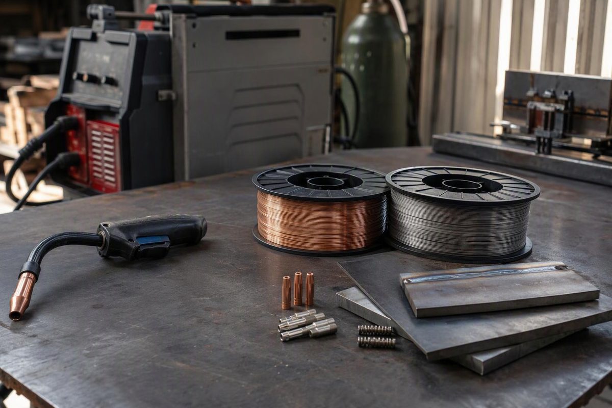
Start with the welder’s chart for your exact wire type, diameter and material thickness, then check it against the wire manufacturer’s operating data. Voltage and wire-feed speed are a pair—not independent “heat” settings.
For example, Lincoln lists 17–18 V at 150 inches per minute (IPM) for .035-inch Innershield NR-211-MP, using DC electrode negative and a 1/2–5/8-inch contact-tip-to-work distance. That is a published operating point for that product, not a universal setting for .035 flux-core wire or a particular plate thickness. Lincoln’s NR-211-MP operating data provides the full range.
Confirm the process and polarity first
Flux-cored wire comes in two different setups:
- Self-shielded FCAW-S: supplies its own shielding through the flux; no external shielding gas is required. NR-211-MP specifies DCEN, meaning the electrode/gun is negative and the work connection is positive.
- Gas-shielded FCAW-G: requires the specified external gas. For comparison, Lincoln UltraCore 71A85 specifies DCEP—electrode positive—with 75–85% argon/balance CO₂.
Those requirements come from the respective NR-211-MP product data and UltraCore 71A85 datasheet. Never set polarity from the words “flux core” alone. If the spool’s process is unclear, review the difference between FCAW-S and FCAW-G before welding.
Example settings for .030 and .035 self-shielded wire
These are selected typical operating points for Lincoln NR-211-MP on mild steel, not a thickness-based welding procedure. Use them to check the voltage/feed-speed relationship, not to replace your machine chart.
| Wire diameter | Wire-feed speed | Voltage | Contact-tip-to-work distance |
|---|---|---|---|
| .030 in. (0.8 mm) | 100 IPM (2.5 m/min) | 13–14 V | 1/2 in. (13 mm) |
| .030 in. (0.8 mm) | 150 IPM (3.8 m/min) | 14–15 V | 1/2 in. (13 mm) |
| .030 in. (0.8 mm) | 200 IPM (5.1 m/min) | 14–15 V | 1/2 in. (13 mm) |
| .035 in. (0.9 mm) | 70 IPM (1.8 m/min) | 15–16 V | 1/2–5/8 in. (13–16 mm) |
| .035 in. (0.9 mm) | 110 IPM (2.8 m/min) | 16–17 V | 1/2–5/8 in. (13–16 mm) |
| .035 in. (0.9 mm) | 150 IPM (3.8 m/min) | 17–18 V | 1/2–5/8 in. (13–16 mm) |
| .035 in. (0.9 mm) | 200 IPM (5.1 m/min) | 18–19 V | 1/2–5/8 in. (13–16 mm) |
Source: Lincoln’s published NR-211-MP operating procedures. All rows specify DCEN.
These wire sizes also have a material-thickness limit: Lincoln recommends NR-211-MP in .030, .035 and .045 inch only on plate up to 5/16 inch (7.9 mm). The restriction applies to every plate in the joint and to both single- and multipass welding; adding passes does not remove it. Lincoln’s Innershield guide, page 22
A dial marked “4” is not necessarily 4 V or 400 IPM. On machines with numbered or lettered controls, use the model-specific chart. Material thickness, joint configuration and welding position all affect the starting settings; Miller describes machine charts as rough guides to refine through test welds. Miller’s flux-cored setup guidance
What the controls actually change
On a conventional constant-voltage flux-core setup:
- Voltage controls arc length. Raising it generally produces a wider, flatter bead. Too little can produce a ropey bead or stubbing; excessive voltage can cause porosity with self-shielded wire.
- Wire-feed speed primarily controls welding current and deposition rate. Increasing feed speed generally requires a corresponding voltage adjustment. Too little feed can let the arc burn back toward the contact tip.
- Contact-tip-to-work distance (CTWD) affects current. At unchanged settings, increasing this distance reduces current; shortening it increases current.
- Travel speed controls how much weld metal and energy are placed along the joint. Traveling too slowly can let slag run ahead of the arc and become trapped.
These relationships are described in Lincoln’s Innershield welding guide, pages 38–42 and 53–56.
CTWD is not stickout. CTWD runs from the contact tip to the work and includes the arc gap. Stickout is the unmelted wire extending beyond the contact tip. Measure the distance named in your wire’s chart, not the distance from the nozzle. Lincoln’s CTWD explanation, pages 39–40
Tune on a representative test joint
- Remove setup faults first. With power isolated as directed by the manual, verify polarity, feed-roll type and size, contact tip, liner and spool tension. Clean the joint and work-clamp contact area. Poor feeding or a resistive work connection can imitate a settings problem. Miller’s preparation and equipment checks
- Match the coupon to the job. Use the same steel thickness, joint type, gap and welding position. A bead on flat scrap does not reproduce a lap joint or open-root groove.
- Set the chart’s voltage/feed pair and specified CTWD. Use a drag technique for the self-shielded setup discussed here. Keep distance and travel angle consistent so hand movement does not obscure the effect of a setting change.
- Make a short weld, remove the slag and inspect it. Change one variable at a time in small increments, then repeat. Keep changes within the wire’s operating range and any applicable welding procedure specification (WPS).
Diagnose the symptom before turning a knob
| Symptom | First checks and adjustment direction |
|---|---|
| Wire repeatedly hits the joint and pushes the gun back | Confirm steady feeding and CTWD. For stubbing, increase voltage within the wire range or reduce feed speed. |
| Wire burns back toward the contact tip | Check for interrupted feeding first. If feeding is steady, wire-feed speed may be too low for the voltage. |
| High, ropey bead | Check excessive CTWD and overly fast travel; insufficient voltage is another likely cause. Increase voltage only within the wire specification. |
| Excessive spatter | Verify polarity, tip condition, feeding and gun distance. Adjust the voltage/feed balance rather than automatically reducing both. |
| Pinholes or worm-like gas marks | Clean contamination and check wire condition. With self-shielded Innershield, excessive voltage is a possible cause—not just insufficient heat. |
These are diagnostic leads, not proof of a single cause. The adjustment directions follow Lincoln’s Innershield parameter and troubleshooting guidance, pages 53–56; its wire-storage guidance on page 58 also identifies moisture as a cause of gas marks and porosity.
For thin steel that burns through, check fit-up and accumulated heat before simply lowering voltage until the arc stubs. For thick steel, a larger surface bead does not prove root fusion. Production and safety-critical work must follow the applicable procedure, qualification and inspection requirements; appearance alone cannot establish internal soundness.
Use proper welding PPE and fume controls during every test. “Gasless” does not mean fume-free, and welding outdoors does not guarantee adequate ventilation. OSHA’s welding-fume guidance explains exposure controls.