
Match Your GMAW Transfer Mode to the Job
Compare GMAW transfer modes, see sourced wire settings, and match shielding gas, polarity and equipment before diagnosing spatter, porosity or poor fusion.
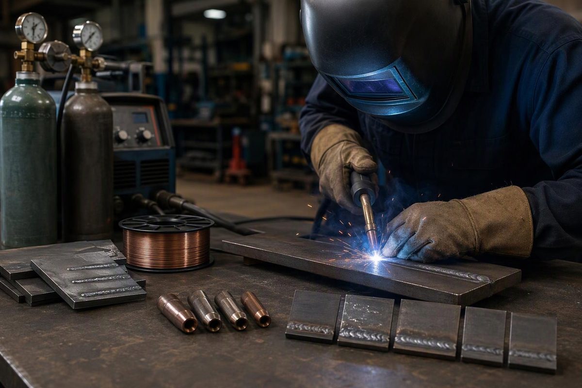
Gas metal arc welding (GMAW) joins metal with an electric arc between a continuously fed consumable wire electrode and the workpiece. The wire supplies filler metal, and externally supplied shielding gas protects the arc and molten pool. For setup, choose the transfer mode, wire and gas to suit the material, joint and position before tuning voltage. A stable arc does not prove adequate fusion. TWI’s process explanation describes the process and its transfer modes.
Choose a transfer mode and welding position to compare two published steel-wire operating points and their limits.
Compare Two L-59 Operating Points
Lower-energy transfer can suit thin material and positional work. Check fusion, joint requirements and the applicable procedure.
Published point: 18 V, 150 in./min, approximately 120 A.
| Parameter | Short Circuit | Spray |
|---|---|---|
| Gas | 75% Ar / 25% CO₂ | 90% Ar / 10% CO₂ |
| Tip-to-work distance | 1/2 in. (12 mm) | 3/4 in. (19 mm) |
| Wire-feed speed | 150 in./min (3.8 m/min) | 375 in./min (9.5 m/min) |
| Voltage | 18 V | 23 V |
| Current | ~120 A | ~195 A |
Position and Measurement Limits
Conventional axial spray generally suits flat or horizontal welding because of its fluid pool. For vertical or overhead work, pulsed spray may provide better control, but requires a pulse-capable source and compatible program. No pulsed settings are supplied here.
Short circuit can suit positional work, but its lower heat input can leave inadequate fusion. Neither operating point establishes acceptance for your joint.
Contact-tip-to-work distance includes the arc gap. It is not nozzle distance or electrical electrode extension. These steel-wire examples are not aluminum settings.
Sources: Lincoln Electric SuperArc L-59 operating data; TWI MIG/MAG process explanation; Miller pulsed-MIG guidance. Currents are approximate.
GMAW Includes Both MIG and MAG
GMAW is the broader process name. Strictly speaking, MIG—metal inert gas—uses inert shielding, such as argon or argon/helium mixtures. MAG—metal active gas—uses an active gas, such as carbon dioxide or an argon mixture containing CO₂ or oxygen.
Aluminum welding typically uses inert shielding; steel welding commonly uses active shielding. In everyday US usage, both are often called MIG. That shorthand appears in Miller’s mild-steel welding guide.
Gas-shielded flux-cored arc welding (FCAW-G) is a separate process, even though it also uses a wire feeder and gas cylinder. Its electrode contains flux; GMAW does not rely on that flux system. GMAW can also use metal-cored wire, as described in Miller’s process comparison. For the flux-cored variants, see FCAW-S versus FCAW-G.
Wire Speed, Voltage and Travel Control Different Things
A feeder moves wire from the spool through the gun liner and contact tip. The contact tip transfers welding current to the wire; shielding gas passes through the nozzle around it. In semiautomatic welding, the machine feeds the wire while the operator controls gun position and travel.
Conventional GMAW generally uses a constant-voltage power source. With wire type, diameter and extension held reasonably consistent, wire-feed speed primarily sets welding current and deposition rate: feeding more wire requires more current to melt it.
Voltage primarily controls arc length. Increasing voltage generally lengthens the arc and makes the bead wider and flatter. Travel speed changes how much energy and filler are placed along the joint.
These controls interact. Voltage is not a standalone penetration control, and a voltage setting without wire speed and travel conditions tells you little about the weld. ESAB’s settings guidance explains these relationships.
Transfer Mode Sets the Process Limits
Transfer mode describes how molten metal moves from the wire into the weld pool.
| Mode | Metal Transfer | Main Use and Limit |
|---|---|---|
| Short-Circuiting | Wire touches the pool; the liquid bridge separates and the arc re-establishes. | Lower-energy operation suits thin material and positional work, but inadequate fusion is a risk. |
| Globular | Large droplets transfer irregularly under gravity’s influence. | Often produces substantial spatter; increasing power does not necessarily produce spray. |
| Axial Spray | Small droplets cross a continuously established arc. | Higher current and a fluid pool suit heavier work, generally flat or horizontal. |
| Pulsed Spray | Peak-current pulses detach droplets; background current maintains the arc. | Better positional control and lower average current, with a pulse-capable source and compatible program. |
Short circuit is useful where a large, fluid pool would be difficult to control. Its lower heat input also makes lack of fusion a concern when settings, technique or joint access are unsuitable. A neat bead can conceal an unfused interface.
Conventional spray transfers metal without repeatedly shorting the wire into the pool. Its fluid pool generally limits it to flat or horizontal welding. Pulse changes that behavior by alternating peak and background current. Miller’s pulsed-MIG guide explains the required equipment and positional benefits.
Shielding gas helps determine which modes are available. For carbon-steel spray or pulsed spray, Miller says an argon content of at least 80% is typically required; 90% argon/10% CO₂ is common. A 75/25 short-circuit setup is therefore not interchangeable with a spray setup. Changing voltage alone does not correct an unsuitable gas selection.
Aluminum needs a different gas selection—not a steel CO₂ blend. Check the wire data and machine program, or use the shielding-gas selection guide.
Match the Setup Before Tuning the Arc
Establish the Joint and Procedure Requirements
Confirm base alloy, thickness, joint preparation, fit-up and welding position. For work governed by a welding procedure specification (WPS), use its permitted process, transfer mode, consumables and operating ranges. A convenient machine setting does not override the procedure.
Match Wire, Gas and Polarity
Conventional solid-wire GMAW normally uses DC electrode positive (DCEP). Verify the consumable and machine instructions rather than carrying over the polarity from a previous flux-core setup.
Confirm gas delivery and set flow according to the applicable instructions. The draft’s sources do not establish one universal gas-flow setting for every nozzle, joint or working environment.
Check the Feed Path and Work Connection
Match drive rolls, liner and contact tip to the wire. Set spool and roll tension according to the manual. Inspect cable connections and attach the work clamp to clean metal—not paint, scale or a convenient surface with an uncertain electrical path.
Miller’s mild-steel guide supports these polarity, feeding, gas, cleanliness and connection checks. For component selection, see building a matched MIG setup.
Start With Applicable Published Parameters
Use the machine chart, consumable data or WPS. Maintain the specified contact-tip-to-work distance, then fine-tune on representative practice joints. Change one variable at a time so the effect remains identifiable.
No thickness-specific recipe can be established from wire diameter alone. The gas, transfer mode, wire extension, joint and position also matter.
Published Settings Need Their Conditions Attached
Lincoln’s SuperArc L-59 data lists these operating points for the same .035-inch (0.9 mm) ER70S-6 wire, both using DCEP:
| Parameter | Short Circuit | Spray |
|---|---|---|
| Shielding gas | 75% Ar / 25% CO₂ | 90% Ar / 10% CO₂ |
| Tip-to-work distance | 1/2 in. (12 mm) | 3/4 in. (19 mm) |
| Wire-feed speed | 150 in./min (3.8 m/min) | 375 in./min (9.5 m/min) |
| Voltage | 18 V | 23 V |
| Approximate current | 120 A | 195 A |
These are manufacturer operating points, not thickness-specific recipes or qualified procedures. They demonstrate why the wire diameter cannot determine settings by itself: gas, transfer mode and tip-to-work distance change between the examples.
Contact-tip-to-work distance includes the arc gap. Electrical electrode extension is the wire length from the contact tip to where the wire melts off. Do not substitute nozzle distance or an unspecified “stickout” measurement for the chart’s stated dimension. Miller explains these measurement differences.
Diagnose the Symptom Before Changing Power
Stubbing Points to Feeding or an Arc-Setting Imbalance
If the wire stubs into the joint or the gun kicks back, first confirm smooth feeding and the correct setup. Then compare voltage with wire-feed speed. Insufficient voltage for the selected feed speed can cause stubbing.
Make a small adjustment within the permitted range rather than changing both controls together. Otherwise, you lose track of which change corrected—or worsened—the problem.
More Spatter May Mean Globular Transfer
If spatter increases after turning up the machine, recheck gas and transfer mode. You may be operating in globular transfer rather than spray. Verify polarity, cleanliness and feed consistency before treating voltage as the only cause.
Porosity Requires a Shielding and Cleanliness Check
Check gas delivery, leaks, nozzle condition, drafts and contaminated material or wire. Do not automatically increase flow: excessive flow can entrain air and worsen porosity. TWI’s porosity guidance identifies both shielding failures and contamination as causes.
Acceptable Appearance Does Not Prove Fusion
Review joint access, preparation, travel speed, arc placement and whether the selected mode supplies suitable energy. Short circuit deserves particular attention because its low heat input can leave unfused interfaces.
Appearance alone does not establish weld soundness or code acceptance. Follow the required inspection and testing plan; see assessing bad welds beyond appearance.
Shielding Gas Does Not Make Welding Safe to Breathe
Use an appropriate welding helmet, safety glasses, gloves and flame-resistant clothing. Control sparks, combustibles and bystander exposure. Inspect equipment and follow the manual’s electrical precautions. OSHA’s US general-industry welding standard sets out workplace fire and personnel protections.
Arrange ventilation or local extraction to remove fume without disrupting shielding. Argon, helium and CO₂ can displace oxygen, and welding outdoors does not guarantee adequate ventilation. Stainless alloys and coated materials require attention to their specific fume hazards.
Confined-space welding needs a site-specific safety system—not merely an open door or fan. Respiratory protection may be required if ventilation and work practices do not adequately control exposure. OSHA’s fume and gas fact sheet distinguishes GMAW from FCAW and explains the hazards and exposure controls.