
How to Evaluate a Brazed Joint for Medical-Device Manufacturing
A joint may corrode, retain unacceptable residue, release particulates, leak above the specified limit or lack adequate production traceability.
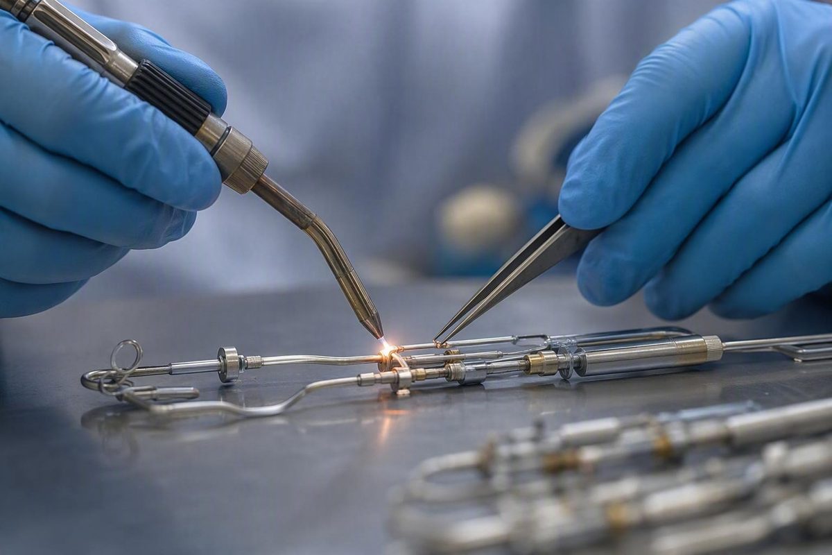
Brazing can solve difficult joining problems in miniature, dissimilar-material, multi-joint, and sealed medical assemblies. It can also introduce new risks if the filler alloy, geometry, thermal cycle, atmosphere, or cleaning process is poorly matched to the application.
The essential distinction is between process capability and medical suitability. Producing a visually sound metallurgical joint shows that the parts can be brazed. It does not establish acceptable cleanliness, corrosion resistance, fatigue life, sterilization durability, hermeticity, biological safety, or traceability for a finished device.
This article is therefore a preliminary engineering-screening framework, not a complete regulatory or validation protocol. The supplied evidence is primarily manufacturer and supplier guidance; it does not include regulator guidance, current certificate scopes, medical-device standards, or independent device-specific validation studies. Applicable requirements must be determined for the actual device, jurisdiction, exposure, and risk classification.
Evaluation should begin with the exact substrates, geometry, joint function, service environment, allowable thermal history, and measurable acceptance criteria—not a general claim that one brazing method or filler is “best.”
What brazing medical components means
Brazing joins components by melting a filler metal while keeping the base materials solid. The liquid filler wets properly prepared surfaces, enters a close-fitting joint, and solidifies into a metallurgical bond.
Capillary action is central to the process. When surface condition, joint clearance, temperature, and filler placement are appropriate, molten filler distributes through the gap. If contamination blocks the path, the gap closes during heating, or the clearance is too large for effective capillary flow, reaching the filler’s melting temperature will not by itself produce an acceptable joint.
Conventional technical guidance defines brazing as using a filler with a liquidus above 840°F (450°C) but below the base metal’s solidus. Soldering uses a filler below that threshold. Because commercial pages sometimes use different descriptions, classification should follow the applicable engineering procedure or standard rather than marketing terminology. Haynes International explains the conventional temperature definition and capillary-bonding mechanism.
Because the base components remain solid, brazing can be investigated for:
- Thin or delicate parts that cannot tolerate local melting
- Miniature joints with limited access
- Dissimilar metals that are difficult to fusion weld
- Metal-to-ceramic interfaces
- Assemblies with several joints heated in one cycle
- Feedthroughs and enclosures requiring a measurable leakage barrier
- Components whose dimensions or appearance require close control
These possibilities do not make brazing inherently preferable to laser welding, resistance welding, soldering, adhesives, diffusion bonding, or mechanical joining. Alternatives should be compared using the actual design constraints: substrate compatibility, heat input, distortion, seal performance, production volume, inspectability, repair strategy, and lifecycle risk.
Most importantly, joint formation is only the first technical question. A braze can be metallurgically sound yet unsuitable because it corrodes, retains unacceptable residue, releases particulates, fails after environmental exposure, leaks above the specified limit, or cannot be produced with adequate traceability.
Where brazed joints appear in medical devices
Suppliers report brazing work involving surgical instruments, implants, diagnostic equipment, implantable devices, and robotic-surgery components. These are supplier-reported application categories, not independent proof that every process or alloy in a supplier’s portfolio is appropriate for those devices. Lucas Milhaupt lists the medical applications it says its joining products and services support.
Ceramic-to-metal joining is a prominent use case. A ceramic may provide electrical insulation, dimensional stability, or wear-related properties, while the metal provides mounting, conduction, structural support, or connection features. Morgan lists active-brazed ceramic-to-metal components for electrosurgical tools, X-ray equipment, life-science instrumentation, and implantable assemblies; those statements remain supplier-authored and require confirmation against the proposed component. Morgan describes its reported medical active-brazing applications.
Other supplier-reported categories include catheters, pacemakers, neuromodulation devices, surgical instruments, orthopedic implants, and diagnostic devices. Named experience can help identify potentially relevant suppliers, but it does not demonstrate equivalent materials, geometry, patient exposure, cleaning, inspection, or production controls.
Sealed enclosures and feedthroughs create two related but distinct requirements. A joint may need to carry mechanical or thermal loads while also acting as a barrier to gas or fluid movement. Neither a continuous fillet nor the word “airtight” establishes hermetic performance. The design needs a quantitative leakage specification and a test method capable of verifying it.
Supplier literature also mentions stainless steel, titanium, nickel and cobalt alloys, copper, brass, Kovar, ceramics, and precious-metal systems. This indicates the breadth of materials encountered, not universal compatibility. Each substrate-and-filler combination must be screened for wetting, thermal expansion, erosion, reaction products, corrosion, and the effects of the complete thermal cycle.
The following table is a set of preliminary engineering questions, not a list of established medical-process recommendations.
| Assembly type | Likely joining challenge | Process options to investigate | Preliminary validation questions |
|---|---|---|---|
| Implantable enclosure or feedthrough | Leakage, corrosion, expansion mismatch, cleanliness | Vacuum or controlled-atmosphere brazing; active brazing for ceramic interfaces | What leak rate is permitted? What changes after relevant aging or environmental conditioning? Are exposed residues and corrosion products acceptable? |
| Surgical or electrosurgical instrument | Thin sections, heat sensitivity, repeated loading | Induction, vacuum, controlled-atmosphere, or another localized process | Does the joint survive representative mechanical and cleaning cycles? Are erosion and distortion controlled? |
| Catheter or neuromodulation component | Miniature geometry, filler control, particulate concerns | Localized induction or qualified furnace processing | Can filler volume and flow be controlled? Which surfaces are exposed? How will residue and particulate risks be assessed? |
| X-ray or analytical assembly | Ceramic-to-metal interface, vacuum integrity, dimensional stability | Active brazing or vacuum furnace brazing | Are reaction-layer thickness, expansion mismatch, outgassing, and leakage acceptable? |
| Diagnostic enclosure | Multiple joints and a defined leakage barrier | Vacuum or controlled-atmosphere batch brazing | Does every joint reach the qualified thermal window? How will internal defects and leaks be detected? |
| Robotic-surgery component | Small geometry, close tolerances, cyclic load | Induction or furnace brazing, depending on access and load size | Is alignment retained? Which fatigue, torque, or dimensional tests represent service? |
| Stainless-steel or titanium subassembly | Distortion, corrosion, appearance, inspectability | Localized heating, vacuum brazing, or an alternative joining method | Does the filler impair corrosion performance? Can the critical bond area be inspected? |
Comparable-joint evidence matters more than a broad industry list. A supplier that has brazed one implantable enclosure may not have qualified the proposed filler, wall thickness, joint clearance, cleaning process, or exposure condition.
Choosing induction, vacuum, controlled-atmosphere, or active brazing
The heating method affects more than filler melting. It influences temperature uniformity, oxide control, cycle duration, fixture behavior, throughput, accessibility, and the evidence needed to show that production remains inside a qualified window.
| Process | Heat localization | Atmosphere control | Geometry and access | Production fit | Main validation considerations |
|---|---|---|---|---|---|
| Induction brazing | High; shaped by coil design and electromagnetic coupling | May use local shielding, flux, or an enclosure | Requires effective coil coupling to the joint region | Dedicated coils and fixtures can suit repeated localized operations | Coil identity and position, power, frequency, time, loading, temperature distribution, and dimensional sensitivity |
| Vacuum or furnace brazing | Low localization; much or all of the load follows the furnace cycle | Process-wide control when vacuum quality is suitable | Useful for multi-joint, complex, or batch-loaded assemblies | Requires load and fixture development | Furnace uniformity, load configuration, ramp and hold profile, vacuum level, cooling, contamination, and joint-to-joint variation |
| Controlled-atmosphere brazing | Usually broad heating, although equipment varies | Uses a specified inert, reducing, or other atmosphere | Useful when atmosphere protection must surround the assembly | May support batch or continuous production | Gas purity, atmosphere metrics, flow, purge sequence, furnace integrity, and atmosphere-material reactions |
| Active brazing | Depends on the heat source | Often combined with vacuum or a controlled atmosphere | Particularly relevant to ceramic-to-metal interfaces | Requires controlled filler placement and reaction development | Ceramic preparation, metallization if used, reaction-layer thickness, expansion stress, cracking, and leakage |
Induction brazing provides localized heating without requiring the entire assembly to follow a furnace profile. Localization can be useful where nearby features have restricted thermal limits, but induction is not automatically faster, safer, or more repeatable for every assembly.
A bounded example comes from an Ambrell trial involving copper and brass fittings. The supplier reports using a custom multiple-turn helical coil and a 10 kW induction system to target 1,400°F (760°C) at approximately 250 kHz. Power and heating time were adjusted iteratively. The report supplies no strength, cycle-time, defect-rate, sample-size, or statistical-repeatability results, so it demonstrates a heating-development exercise rather than medical validation or production readiness. Ambrell documents the reported equipment and trial parameters.
Vacuum brazing can limit oxidation and exposure to atmospheric contamination. It is worth investigating for multi-joint assemblies, internal filler preforms, or complex loads where broad, comparatively uniform heating is more useful than localization.
Controlled-atmosphere brazing uses a specified gas environment. “Controlled atmosphere” is not one interchangeable condition: high-purity argon, hydrogen, vacuum, and other environments interact differently with oxides, fillers, base materials, furnace hardware, and safety systems. The atmosphere must be selected and monitored for the actual material system.
Active brazing uses a filler capable of reacting with and wetting a ceramic surface. Ceramic preparation, active-element behavior, reaction-layer development, thermal expansion, residual stress, cracking, and leakage still require evaluation.
Furnace guidance should not be copied directly into an induction, torch, or other localized process. That difference can change filler flow, base-material condition, fixture movement, reaction-layer thickness, distortion, and residual stress.
A practical selection sequence is:
- Identify every substrate, coating, plating, metallized layer, and filler candidate.
- Define the joint’s structural, electrical, thermal, and sealing functions.
- Set preliminary cleanliness, residue, particulate, outgassing, and leakage criteria.
- Establish the allowable thermal window for every component.
- Assess accessibility, thermal mass, number of joints, and production load size.
- Select a candidate heating method and atmosphere.
- Develop measurable process parameters on representative assemblies.
- Determine what additional device-specific and regulatory evidence is needed before approval.
Selecting a filler metal without treating “medical grade” as a shortcut
Filler selection is a material-system decision, not a label-selection exercise. The alloy must be compatible with the base materials, hot clearance, heating method, peak temperature, time at temperature, service exposure, load case, and joint geometry.
Gold-, silver-, nickel-, copper-, cobalt-, palladium-, and active-braze families are documented options. Each family contains different compositions, melting behavior, flow characteristics, corrosion performance, and reaction risks. No family is universally suitable for medical use.
The following examples are supplier listings, not recommendations for implants, patient-contacting components, or any particular substrate:
| Supplier-listed alloy | Nominal composition | Supplier-listed melting range | Supplier-listed classification |
|---|---|---|---|
| Au25-Cu75 | 25% gold, 75% copper | 1,017–1,030°C | Not listed |
| Au35-Cu62-Ni3 | 35% gold, 62% copper, 3% nickel | 990–1,010°C | AWS BVAu-3 |
| Au35-Cu65 | 35% gold, 65% copper | 990–1,010°C | AWS BVAu-9 Grade 1 |
| Au82-Ni18 | 82% gold, 18% nickel | 949°C | AWS BVAu-4; AMS 4787 |
| PAL 5 | 68% silver, 27% copper, 5% palladium | 806–809°C | AWS BVAg-30 |
These compositions, temperatures, and classifications come from Prince & Izant’s medical-market table. The page provides no assembly-specific strength, fatigue, corrosion, sterilization, or biological-suitability results. Prince & Izant publishes the listed alloy data.
AWS or AMS classifications can identify chemistry or procurement requirements. Nothing in the supplied evidence establishes those classifications as medical-device approvals or proof of implant suitability.
Selection should address at least:
- Wetting and compatibility: Will the filler wet the prepared substrate without an unacceptable coating or metallization system?
- Hot clearance: Is the alloy’s flow behavior suitable for the actual gap at brazing temperature?
- Thermal window: Can the filler melt and flow without damaging base materials, coatings, electronics, or earlier joints?
- Mechanical duty: Does representative testing address the expected static, cyclic, impact, vibration, torque, or thermal loads?
- Corrosion exposure: Could the joint encounter cleaning chemicals, moisture, galvanic couples, physiological exposure, or a sensitive sealed atmosphere?
- Reaction products: Could diffusion produce brittle phases, excessive erosion, penetration, or an unacceptable reaction layer?
- Manufacturing form: Can wire, foil, paste, powder, sheet, or a preform deliver a controlled quantity?
- Exposure: Which filler constituents, residues, corrosion products, or diffusion products could reach a relevant device surface or internal environment?
Documented risks are conditional. Boron-bearing nickel fillers can form brittle borides; phosphorus-bearing copper fillers can create nickel phosphides at nickel-containing bond lines; molten silver-rich filler can cause liquid-metal embrittlement in stressed nickel alloys; and filler-base-metal reactions can erode or penetrate thin sections. The exact risk depends on alloy, stress, temperature, geometry, and environment. The ScienceDirect materials overview discusses filler compatibility, reaction, and thin-section risks.
Terms such as “high purity,” “biocompatible,” and “medical grade” may describe supplier positioning, but they do not establish finished-assembly suitability. Depending on the device-specific assessment, questions may need to cover:
- Bulk filler constituents
- Platings and metallized layers
- Diffusion products and intermetallic compounds
- Flux and cleaning residues
- Corrosion and wear products
- Particulates and outgassing
- Whether the joint is exposed, encapsulated, or isolated
- Exposure route and duration
- The intended environmental and sterilization conditions
The evidence supplied for this article does not establish which biological, chemical, or sterilization endpoints apply to a particular device. Those determinations require separate, authoritative device-specific assessment.
Designing the joint for capillary flow and controlled thermal stress
Joint design must give molten filler a controlled path while keeping the assembly stable during heating and cooling. Important inputs include clearance, surface finish, filler form and location, overlap, thermal-mass balance, component restraint, heat access, and inspection access.
Clearance must be evaluated at brazing temperature, not only on a room-temperature drawing. Dissimilar materials expand by different amounts, and the direction of gap change depends on the joint configuration and restraint. A shaft inside a sleeve may open or close its gap depending on which member expands more.
A gap that is too narrow can restrict filler entry or trap gas and contamination. Excessive clearance weakens capillary action, increases the required filler volume, and can make performance depend more heavily on the filler’s bulk properties.
For nickel- and cobalt-base alloy systems covered by manufacturer guidance, approximately 0.001–0.005 inch (0.025–0.125 mm) is recommended at brazing temperature. This is not a universal medical-component specification. The appropriate target depends on substrate expansion, filler behavior, flow length, tolerances, heating method, and service requirements. Lucas Milhaupt’s brazing fundamentals explain hot-clearance behavior and the consequences of gaps that are too narrow or too wide.
Room-temperature dimensions should be derived from the required hot condition. Thermal estimates should then be checked through representative heating trials and cross-sections. Plating thickness, ceramic tolerances, fixture restraint, and part-to-part variability must be included.
Butt joints preserve a single-thickness profile but limit bonded area to the relevant cross-section. They may be appropriate where overlap is impossible or the loading is favorable.
Lap joints provide more potential bonded area but add thickness, create a longer capillary path, and may be harder to inspect completely. General guidance sometimes proposes a lap length near three times the thinner member’s thickness. That is preliminary guidance, not a validated design allowable for a critical medical assembly.
Induction coupling can intensify this difference when materials or geometries heat at different rates.
Fixtures should maintain alignment without overconstraining thermal expansion. Excess restraint can store stress during heating or cooling; insufficient restraint can allow the gap to change, filler to drain, or components to distort. Fixture materials also must remain compatible with the atmosphere and avoid contaminating or bonding to the assembly.
For ceramic-to-metal joints, expansion mismatch can place tensile stress in the ceramic or reaction layer. Matched-expansion combinations may reduce this risk, while intentionally mismatched or compression-seal designs need defensible analysis and physical testing. Cracking can appear during cooling or later environmental and mechanical exposure.
The drawing and process documentation should define, where applicable:
- Room-temperature dimensions corresponding to the intended hot gap
- Hot-gap target and acceptable variation
- Surface finish and preparation
- Filler alloy, form, quantity, and location
- Joint overlap and stop-off boundaries
- Fixture identity, orientation, and restraint
- Heating method, thermal cycle, and atmosphere
- Cooling conditions
- Permitted fillet or overflow condition
- Inspection locations, methods, and acceptance criteria
Controlling cleanliness, atmosphere, heat, and production records
A practical brazing process can be organized into six stages. Each should have defined inputs, measurable controls, and records proportionate to the component’s risk.
1. Fit and clearance
Confirm substrate identity, dimensions, coatings, plating, alignment, and filler location before heating. Measurements should represent the features governing hot clearance, not merely convenient external dimensions.
Where ceramic tolerances, plating buildup, or thin-wall distortion materially affect the gap, those variables belong in process development. A nominally correct design can fail if accumulated variation closes the capillary path.
2. Cleaning
Oils, paint, ink, chemical residue, oxides, scale, and particulates can interfere with wetting and contribute to incomplete bonding, voids, inclusions, discoloration, or leakage.
A typical sequence may use solvent cleaning or degreasing followed, where appropriate, by mechanical cleaning, pickling, oxide removal, or another material-specific treatment. The method must not damage thin sections, alter critical dimensions, embed abrasive material, or attack coatings and metallized ceramic layers.
Visible cleanliness is not necessarily sufficient. The assembly-specific evaluation may need to ask how nonvolatile residue, ionic contamination, particulates, cleaning-agent carryover, or outgassing will be limited and verified. The evidence pack does not define universal medical limits for those characteristics.
3. Flux or atmosphere selection
Flux can disrupt oxides, protect surfaces during heating, and support wetting. It must remain active through the relevant temperature range and should be removed after brazing. Crevices that retain flux or cleaning chemistry require particular attention.
Vacuum, high-purity inert gas, hydrogen, and other environments are process-specific options, not interchangeable solutions. Suitability depends on oxide stability, filler chemistry, furnace construction, component materials, and contamination risks. A gas name alone is not a complete atmosphere specification.
4. Assembly and fixturing
Preforms, wire, foil, paste, or powder should be positioned so the molten volume feeds the intended joint without flooding functional surfaces.
Small or cosmetically sensitive components also require controlled loading and racking. Contact marks, fixture reactions, part-on-part damage, and movement during furnace evacuation or gas flow should be evaluated.
5. Heating and cooling
Temperature, time, heating rate, atmosphere quality, cooling rate, load configuration, and filler quantity can alter both the joint and the base materials. A furnace setpoint does not prove that every joint reached the same thermal condition. Likewise, induction power and time are incomplete without coil position, coupling distance, orientation, and temperature evidence.
For the nickel- and cobalt-base systems addressed by Haynes, the manufacturer advises minimizing exposure through approximately 1,000–1,800°F (538–982°C) because secondary-phase precipitation can impair properties, including corrosion resistance. That window should not be generalized to stainless steel, titanium, copper, Kovar, ceramics, or other systems. Haynes provides the alloy-specific thermal-exposure guidance.
Cooling deserves equivalent attention. Expansion mismatch, phase formation, fixture restraint, and steep gradients can generate cracks or distortion even when initial filler flow appears acceptable.
6. Post-braze cleaning
Post-braze operations may remove flux, oxides, stop-off, furnace deposits, discoloration, or loose filler. Cleaning must preserve the joint and base materials while reaching recesses capable of trapping residue.
If pickling, blasting, grinding, electropolishing, passivation, or another finishing process follows brazing, its effects should be included in assembly evaluation.
A production traveler may need to capture:
- Base-material, plating, ceramic, and filler lots
- Filler form and quantity
- Cleaning batch and chemistry status
- Fixture, furnace, or induction-coil identity
- Furnace load map or component orientation
- Program revision and temperature record
- Vacuum or atmosphere record
- Heating time, power, frequency, and cooling data where applicable
- Operator and equipment identity
- In-process and final inspection results
- Cleaning verification
- Nonconformances, rework, and disposition
- Approved deviations and change assessments
The objective is reconstruction: if a leak, crack, corrosion issue, or dimensional failure occurs, investigators should be able to identify the relevant material lot, furnace load, coil, fixture, atmosphere, and cleaning batch.
Defects, hermeticity, and inspection planning
Inspection should be selected from the failure mode backward. No single test demonstrates complete integrity, and an acceptable-looking fillet can coexist with internal voids, incomplete wetting, brittle reaction products, or a connected leak path.
| Defect or failure | Likely contributors | Preventive controls | Possible verification |
|---|---|---|---|
| Incomplete wetting | Oxides, oils, poor preparation, incorrect atmosphere, insufficient temperature | Cleaning, oxide control, atmosphere monitoring, thermal confirmation | Visual inspection, metallography, sectioning |
| Insufficient filler flow | Incorrect gap, poor placement, uneven heating, insufficient volume | Hot-gap control, thermal profiling, controlled preforms | X-ray where suitable, metallography, destructive sectioning |
| Voids | Contamination, trapped gas, interrupted flow | Cleaning, vent paths, controlled heating and filler quantity | X-ray, ultrasonic testing where suitable, metallography |
| Inclusions or residue | Flux entrapment, particles, furnace contamination, stop-off migration | Controlled materials, cleaning, furnace maintenance | Visual, residue analysis, metallography |
| Oxidation | Poor vacuum, impure gas, furnace leaks, inadequate flux protection | Atmosphere limits, monitoring, leak checks, qualified flux | Visual inspection, surface analysis where justified |
| Cracks | Expansion mismatch, restraint, residual stress, embrittlement | Material screening, fixture review, controlled cooling | Compatible penetrant methods, X-ray, microscopy, leak testing |
| Distortion | Uneven thermal mass, poor support, excessive temperature or time | Fixture development, profiling, controlled loading | Dimensional or optical inspection |
| Erosion or penetration | Excess temperature, long hold, too much filler, thin section | Filler limits, cycle control, minimum-wall assessment | Cross-sections, dimensions, suitable X-ray |
| Brittle compounds | Incompatible chemistry, excessive reaction time | Material screening, restricted cycle, reaction-layer limits | Metallography, microhardness, qualified material analysis |
| Leak | Incomplete bond, crack, connected porosity, poor fit-up | Joint-design, atmosphere, and thermal controls | Helium, vacuum, or pressure testing |
| Corrosion | Filler/substrate mismatch, galvanic effects, residue, exposure | Corrosion-focused selection and residue control | Relevant immersion, electrochemical, or aging tests |
Hermeticity must be expressed as a measurable requirement. “Airtight,” “leak-proof,” and “completely leak-tight” are not acceptance criteria.
A hermetic specification should identify:
- Maximum permitted leak rate
- Test gas
- Pressure differential and direction
- Dwell, pressurization, and stabilization times
- Test temperature and configuration
- Gross-leak and fine-leak methods, if both are needed
- Calibration and reference-leak provisions
- Sampling plan or complete-inspection requirement
- Retest rules and failure disposition
- The point in processing or environmental conditioning when testing occurs
The evidence supplied here does not establish a universal medical leak limit. An appropriate limit depends on factors such as enclosure volume, internal components, expected service life, external environment, and the consequences of ingress or egress.
Possible inspection tools include:
- Helium leak testing for fine leakage paths under a specified configuration
- Vacuum testing under controlled pressure conditions
- Pressure or proof testing for gross leakage or structural response
- X-ray inspection for certain voids, filler-distribution problems, and geometric discontinuities
- Ultrasonic testing where materials and geometry permit useful signal transmission
- Visual inspection for surface condition, fillets, overflow, oxidation, and obvious cracks
- Metallography for wetting, reaction layers, erosion, porosity, and intermetallic compounds
- Mechanical testing for static strength, torque, peel, fatigue, or another representative load case
One supplier reports vacuum equipment capable of reaching 10⁻¹⁰ Torr and X-ray equipment rated at 160 kV. The 10⁻¹⁰ Torr statement is a reported vacuum-pressure capability—not a dimensioned leak rate, detector sensitivity, measured assembly performance, or universal acceptance criterion. Elcon describes its reported equipment and inspection capabilities.
Test capability must match the defect. Leak testing evaluates seal integrity but may not identify a brittle joint that has not cracked. Metallography is destructive and samples selected locations. A tensile result may not represent fatigue, torque, peel, thermal cycling, or the actual service load.
Where relevant to the intended service, the engineering plan can also ask whether corrosion, aging, environmental conditioning, or post-sterilization testing is needed. The supplied evidence does not determine which of those tests is mandatory for a particular device.
Medical validation and supplier qualification checklist
The following checklist is a preliminary supplier-screening framework. It is not sufficient by itself to demonstrate regulatory compliance or finished-device suitability.
Separate the available evidence into three layers:
- Facility credentials: certification claims, stated scope, calibration practices, training, record control, and nonconformance procedures.
- Manufacturing-process evidence: data showing that the proposed materials, equipment, fixtures, atmosphere, thermal window, cleaning process, and inspections can repeatedly meet defined criteria.
- Finished-assembly evidence: results for the actual or genuinely representative assembly under its relevant mechanical, leakage, corrosion, cleanliness, environmental, and exposure conditions.
A credential does not replace process or assembly evidence. ISO 9001, AS9100D, NADCAP approvals, FAA repair-station certification, ITAR registration, and RoHS compliance may describe particular organizational, process, trade, or product controls. The supplied evidence does not establish any of them as proof that a proposed medical-device braze is acceptable.
Prince & Izant states that it is ISO 13485 certified. Its page does not provide the certificate, issuing body, current status, expiration, relevant facility, or confirmation that the proposed brazing operation falls within scope. Those details should be checked directly rather than inferred from the marketing statement. The supplier’s medical page contains its ISO 13485 claim.
Supplier questionnaire
Scope and comparable experience
- Which legal entity and facility would perform the work?
- What current certificates and scope statements can the supplier provide?
- Which brazing, cleaning, inspection, and finishing operations are in scope?
- Which operations are subcontracted?
- Has the supplier processed the same substrates, coatings, wall thicknesses, ceramic types, and joint geometry?
- What test evidence makes the previous assembly genuinely comparable?
Material and lot control
- How are metals, ceramics, plating, metallization, fillers, fluxes, stop-off, and cleaning chemicals identified?
- Are certificates linked to production lots?
- How are filler composition, form, storage, shelf life, and quantity controlled?
- How is unauthorized substitution prevented?
Process development
- Which parameters define the proposed process window?
- How were joint temperature and uniformity measured?
- Were worst-case gaps, thermal masses, furnace positions, or coil locations evaluated?
- What limits apply to filler quantity, atmosphere quality, heating rate, hold time, and cooling?
- What sample size and analysis support any repeatability claim?
Cleaning and contamination
- What pre-braze and post-braze cleaning processes are used?
- How are chemistry, concentration, bath condition, rinsing, and drying controlled?
- Can inaccessible crevices retain flux or cleaning agents?
- How is cross-contamination from fixtures, baskets, furnace hardware, or other materials controlled?
- What assembly-specific cleanliness characteristics can the supplier measure?
Inspection and acceptance
- Which defects can each inspection method detect?
- What quantitative criteria apply?
- Are leak-test settings, reference standards, calibration status, and raw results retained?
- How are metallographic locations selected?
- How do destructive coupons represent the production assembly?
- At what manufacturing stage does final inspection occur?
Records and change control
- Can each component be traced to material and filler lots, cleaning batch, fixture or coil, furnace load, thermal record, atmosphere record, operator, and inspection result?
- How are nonconforming loads segregated and investigated?
- Who approves rework, reheating, repair, or concessions?
- How will the customer be notified before material, equipment, process, or subcontractor changes?
- How are electronic records protected from undocumented alteration?
For a critical joint, ask for quantitative data from representative assemblies. Depending on function, useful evidence might include strength, fatigue, torque, corrosion, leakage, defect rates, aging, and between-lot repeatability. Results from a different substrate, filler, wall thickness, gap, or heating method should not automatically be treated as equivalent.
Device-specific assessment may also raise questions about biological evaluation, cytotoxicity, extractables, corrosion in the relevant environment, residues, particulates, outgassing, sterilization compatibility, and post-sterilization performance. This evidence pack does not establish when those endpoints apply or how they should be tested; authoritative requirements must be identified separately for the actual device.
Changes to filler alloy or lot, geometry, clearance, induction coil, fixture, furnace load, cleaning chemistry, atmosphere, thermal cycle, or finishing can affect wetting, microstructure, residue, stress, corrosion, dimensions, and inspectability. Each proposed change should therefore receive a documented technical impact assessment, with additional qualification when the identified risk warrants it.
Named experience with pacemakers, implants, catheters, or surgical tools is useful for screening, but it does not prove that a supplier’s entire alloy portfolio or every process is suitable. Byron Products, for example, advertises vacuum and controlled-atmosphere brazing for medical applications, process documentation, and several nonmedical quality credentials, but its page supplies no joint-specific medical validation data. Byron Products describes its reported medical processing capabilities.
A disciplined go/no-go review should follow this order:
- Define joint functions and credible failure modes.
- Confirm substrate, coating, filler, and atmosphere compatibility.
- Establish measurable joint, cleanliness, dimensional, and leakage criteria.
- Review facility scope and subcontracted operations.
- Qualify the manufacturing process on representative or worst-case parts.
- Obtain the device-specific evidence needed for the actual exposure and service conditions.
- Maintain traceable production and change-control records.
Its articles are informational and offered without a guarantee of fitness for a particular purpose, as stated in its terms of use.
Frequently asked questions
What is the difference between brazing and soldering for a medical component?
Both processes use molten filler while the base materials remain solid. The conventional distinction is the filler-metal liquidus: brazing uses filler above 840°F (450°C), while soldering uses filler below that threshold.
Temperature classification does not determine medical suitability. Engineers still need to compare materials, geometry, heat exposure, mechanical duty, corrosion, cleanliness, sealing performance, and relevant environmental conditions.
What joint clearance should a medical braze use?
There is no universal medical-braze clearance. The correct gap depends on the filler, base materials, geometry, flow distance, surface condition, dimensions, tolerances, heating method, and differential thermal expansion.
For the nickel- and cobalt-base systems discussed earlier, manufacturer guidance gives approximately 0.001–0.005 inch at brazing temperature. That range should not be copied directly into an unrelated stainless-steel, titanium, copper, Kovar, or ceramic-to-metal design. The manufacturer’s fundamentals guide explains why clearance must be assessed at brazing temperature.
Determine the required hot gap, calculate the corresponding room-temperature condition, and verify it through representative thermal trials and cross-sections.
Can brazing join ceramic components to metal?
Yes. Active brazing is used for some ceramic-to-metal joints because active filler constituents can promote wetting of ceramic surfaces. Vacuum or controlled-atmosphere processing may be combined with the active-braze system. Morgan reports ceramic-to-metal active-brazing work for several medical application categories.
Successful wetting does not settle the design. Ceramic preparation, metal compatibility, reaction-layer thickness, thermal-expansion mismatch, residual stress, cracking, corrosion, and leakage still require evaluation.
Does ISO 13485 certification prove that a brazed assembly is suitable for an implant?
No conclusion of that kind can be drawn from the supplier certification claim alone.
Review the certificate’s status, issuing body, facility, expiration, and scope. Then evaluate the proposed process and finished assembly separately using traceability and performance evidence relevant to the actual component.
How is a hermetically brazed medical enclosure tested?
The test plan begins with a quantitative leakage specification defining the maximum permitted leak rate, test gas, pressure differential, dwell time, configuration, calibration provisions, sampling plan, and failure disposition.
Helium, vacuum, and pressure methods can assess different aspects of seal integrity. X-ray may identify some internal discontinuities, while metallography can assess wetting, reaction layers, erosion, and local porosity. Passing a leak test does not establish mechanical durability, so representative load or fatigue testing may also be needed. Elcon identifies helium, vacuum, pressure, and X-ray methods among its reported capabilities.
Do not begin by asking which brazing method or alloy is best in general. Begin with the component’s substrates, geometry, joint function, exposure conditions, allowable thermal history, cleanliness needs, and measurable acceptance criteria. Use those requirements to choose a candidate filler and heating process, then qualify the process and obtain finished-assembly evidence for the actual mechanical, corrosion, environmental, hermetic, and exposure risks. Supplier certifications and application lists can narrow the field, but approval should rest on traceable records and test evidence from a genuinely comparable assembly.