
A Crack-Controlled Method for Repairing Gray Cast Iron
Choose gradual, uniform full preheating or an approved low-heat nickel method with short separated beads, then control cooling to limit cracking.
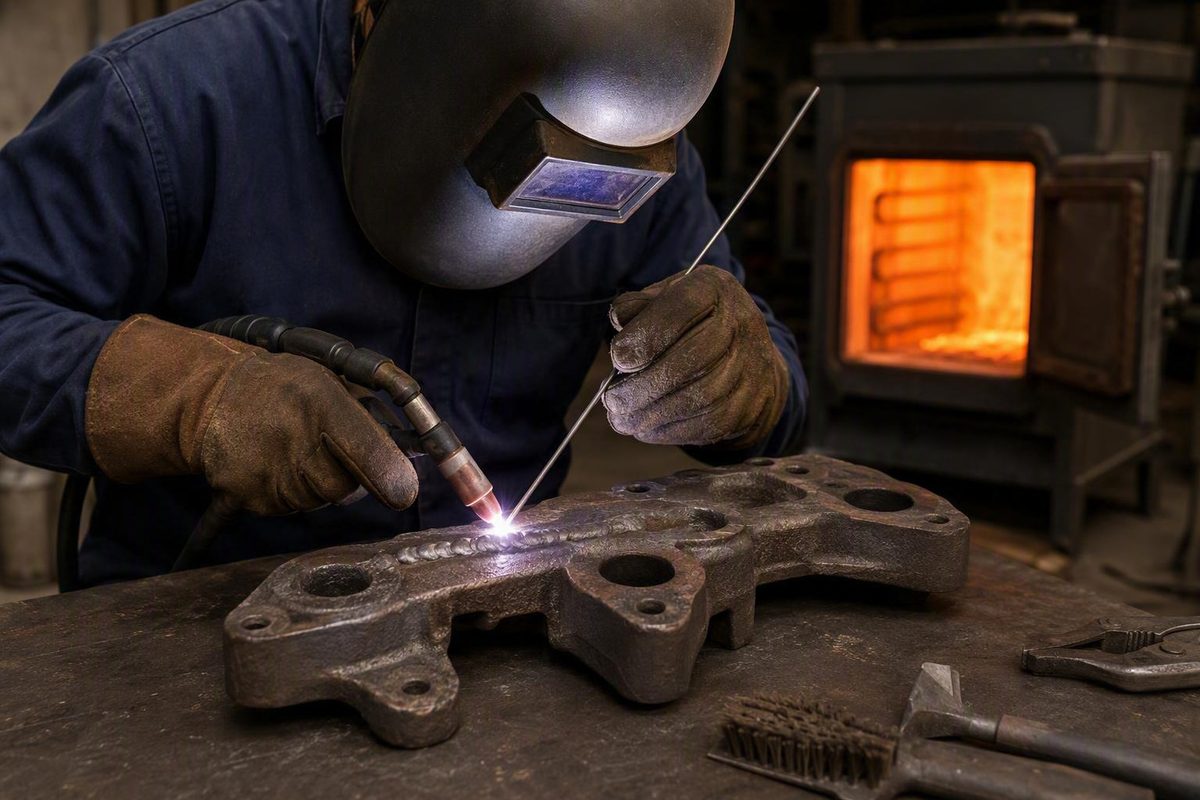
A crack-controlled method for repairing gray cast iron
Learning how to weld cast iron is less about finding a “magic” rod than controlling three variables: material uncertainty, contamination, and heat. A dependable repair begins by deciding whether the casting belongs in a welding bay at all. If it does, expose the complete defect, match the filler to the required deposit properties, and commit to one thermal strategy:
- Gradual, reasonably uniform preheating followed by very slow cooling, or
- A deliberately low-heat method using a suitable nickel-based consumable, short separated beads, controlled peening where permitted, and defined cooling intervals.
This guide focuses on probable gray cast iron. It is a general framework for experienced DIY users, welders, and maintenance personnel—not a qualified welding procedure and not an assurance that a repaired part will recover its original strength, accuracy, fatigue life, leak resistance, or service life.
Decide whether the casting should be welded at all
Before choosing a rod or striking an arc, classify the part and the consequences of a failed repair. A cracked machine cover and a cracked lifting component may both look weldable, but they do not present remotely comparable risks.
Evaluate these factors first:
- Probable cast-iron type: Gray, ductile, malleable, austenitic, and white irons do not respond identically to welding.
- Consequence of failure: Determine what could happen if the repair separates suddenly in service.
- Geometry and section changes: Thin walls, heavy bosses, ribs, corners, and abrupt changes in thickness heat and contract at different rates.
- Restraint: A crack trapped between rigid sections accumulates more stress than an unconstrained edge repair.
- Contamination: Used housings, manifolds, pumps, and machinery castings may retain oil or process residue within their pores.
- Required properties: The repair may need to be machinable, dimensionally accurate, leak-resistant, heat-resistant, or able to carry cyclic loads.
- Heating access: A full-preheat method requires a practical way to heat the casting gradually and cool it under control.
- Replacement economics: A technically possible repair can still be the wrong choice when a suitable replacement is readily available.
Most general repair instructions, including this guide, apply primarily to gray iron. Gray iron contains graphite flakes and is commonly repaired, but it remains crack-prone. Austenitic irons introduce additional service-property concerns. White iron is exceptionally hard and brittle, making it impractical for fusion welding in most ordinary repair settings, although that is more defensible than claiming it can never be welded under any circumstances.
If the iron grade materially affects safety or repair feasibility, consult the original drawing, equipment documentation, or material specification. Otherwise, obtain metallurgical or spectrochemical identification. Fracture appearance and spark testing may provide clues in experienced hands, but they are not conclusive novice identification methods. Reliable identification should come from original specifications or analysis when the alloy matters to the decision (Reliance Foundry’s cast-iron welding overview).
Stop and seek professional assessment when:
- The alloy is unknown and the component is consequential.
- The part belongs to a braking, steering, or suspension system.
- It is part of lifting, hoisting, rigging, or personnel-support equipment.
- It contains pressure or hazardous material.
- It experiences heavy cyclic, impact, or shock loading.
- Cracking is extensive, branched, or present in multiple areas.
- Embedded contamination cannot be removed reliably.
- Precision bores, sealing faces, or alignment features are vulnerable to distortion.
- The casting cannot be supported, heated, or cooled in a controlled manner.
- A failed weld could injure someone or cause major secondary damage.
Major fractures may require professionally designed mechanical repair, reinforcement, or replacement instead of fusion welding. Studding and related mechanical methods appear in cast-iron repair guidance, but they require their own engineering and inspection and should not be treated as fallback DIY techniques.
For an appropriate, noncritical gray-iron repair, proceed only after defining what “acceptable” means. A cosmetic crack repair has different requirements from a machined bearing housing or a liquid-containing casting. If the required acceptance criteria are not known, the repair is not ready to begin.
Why cast iron cracks during welding
Cast iron commonly contains approximately 2% to 4% carbon, substantially more than ordinary low-carbon steel, and generally has much less ductility. That combination makes it less able to stretch or yield as a weld heats, expands, contracts, and cools (Lincoln Electric’s gray cast-iron repair guidance).
During welding, a small area next to the arc rises rapidly in temperature and tries to expand. The larger, cooler mass around it restrains that movement. When the weld pool solidifies and cools, the deposited metal and heat-affected area contract, but the surrounding casting again resists them. Ductile steel can accommodate some of this movement through local yielding. Brittle cast iron has much less capacity to do so, allowing the accumulated stress to produce a crack.
Metallurgy adds another difficulty. Rapid cooling can form a hard, brittle weld-adjacent region. Carbon or graphite entering the molten pool can also harden or embrittle the deposit through dilution. A bead may therefore look satisfactory on the surface while a narrow, crack-sensitive zone develops beside it. Carbon migration, local hardening, and uneven cooling can interact to create brittle weld regions in gray and ductile iron (Metal Supermarkets’ explanation of cast-iron cracking).
These effects explain why the following practices increase risk:
- Long continuous beads accumulate contraction along one line.
- Excessive current enlarges the molten and heat-affected zones.
- Deep penetration increases dilution and disturbance of the base iron.
- Uneven local preheating makes one region expand against a colder, restrained mass.
- Repeated passes in one small area create a concentrated hot zone.
- Forced cooling steepens thermal gradients and can harden adjacent metal.
- Poor crater filling leaves stress concentrators at segment ends.
Cracks can form through the weld, along its toe, just outside the visible bead, or during cooldown after the repair initially appeared sound. The organizing principle for the entire job is therefore heat control. Filler selection matters, but no electrode can compensate for an unsuitable component, an incompletely prepared crack, uncontrolled heat, or abrupt cooling.
Choose the process, filler, and thermal strategy together
For a general gray-iron repair, SMAW, or stick welding, with a cast-iron repair electrode is the most broadly supported starting point. It provides purpose-made consumables, convenient short-deposit control, and field practicality. That does not establish that stick welding is always stronger or more reliable than every alternative.
The process, filler, and thermal strategy form one system. Do not select them independently.
Filler-metal priorities
Choose the required deposit properties before considering a product name:
- Nickel-rich filler: Commonly selected for a comparatively ductile, machinable deposit. It is often considered when the repair must later be drilled, tapped, bored, filed, or milled.
- Nickel-iron filler: Often used when greater deposit strength, multipass buildup, or a different balance of ductility and dilution tolerance is required.
- Other nickel alloys: May be selected for crack resistance, contamination tolerance, dissimilar ferrous joining, or particular service conditions.
- Iron-rich or ordinary steel filler: Can produce a hard deposit or interface and should not be treated as interchangeable with a machinable nickel deposit.
- Copper-alloy filler: Used in brazing and braze-welding methods where reducing base-metal melting is advantageous.
Selection depends on the identified iron, pass count, joint restraint, contamination, required machinability, service temperature, loading, crack resistance, and whether color or rust appearance matters.
Manufacturer guidance illustrates these distinctions. For example, Lincoln Electric differentiates a high-nickel electrode intended for machinable, often single-pass repairs from a nickel-iron option intended for multipass work. It also lists an iron-rich option for repairs that do not require machining. These are product-specific recommendations, so the current consumable data sheet—not the product name alone—must govern the job.
Process choices
Stick welding: The best-supported general starting point for gray-iron repair, particularly when short deposits and a purpose-made nickel or nickel-iron electrode suit the work.
TIG fusion welding: Can work in selected circumstances and offers precise puddle control, but its concentrated heat does not eliminate the thermal-gradient problem. Filler compatibility, penetration, and heat distribution remain critical.
MIG or flux-cored welding: Specialized wires and procedures exist. Ordinary solid steel MIG wire should not be assumed suitable merely because it deposits metal. The supplied evidence does not establish MIG as broadly more dependable than stick welding for gray-iron crack repair.
Oxy-fuel fusion welding: Can distribute heat over a wider area, but it is a distinct high-preheat process requiring compatible filler and careful temperature control.
Brazing or braze welding: These methods use a lower-melting filler without fully melting the cast-iron base metal. Reduced base-metal melting can limit dilution and some fusion-related thermal effects. Suitability still depends on joint design, service temperature, appearance, loading, and dimensional requirements. Brazing is neither automatically inadequate nor a guarantee that the casting’s original properties will be restored.
Choose one heat strategy before welding
Two coherent frameworks are available:
- Full-preheat strategy: Heat the entire casting gradually and reasonably uniformly, maintain thermal balance during welding, and then cool it very slowly.
- Deliberately low-heat strategy: Use a consumable whose manufacturer permits the method, make very short separated deposits, observe its cooling or interpass requirements, peen suitable beads where directed, and prevent a concentrated hot zone.
Do not casually combine their assumptions. A low-heat procedure loses its purpose if repeated beads make the casting progressively hotter without a defined limit. Conversely, a full-preheat procedure should not allow isolated sections to chill unpredictably.
Once the consumable is selected, follow its current, polarity, preheat, interpass, peening, and cooldown instructions. There is no universal amperage or temperature suitable for every iron grade, electrode diameter, casting thickness, and joint.
Prepare the casting and expose the entire defect
Cast-iron repair often succeeds or fails before the arc starts. A narrow groove over the visible portion of a crack is inadequate if the crack continues beneath paint, through a rib, or below contaminated surface metal.
Preparation checklist
- Remove the part where practical. Better access makes preparation and heat management easier.
- Support it naturally. Do not force a distorted casting into alignment unless the repair has been designed around that restraint.
- Remove accessible contamination and unsound material. Clear paint, rust, oil, grease, casting skin, embedded sand, graphite-rich surface material, porosity, and damaged metal.
- Expose sound metal around the repair. A bright surface is not proof that embedded contamination is gone, but it provides a usable starting point.
- Locate the full crack before grinding. Grinding can erase the visible line while leaving part of the defect in place.
- Stop-drill known crack tips where appropriate. A correctly located hole can blunt a known crack tip, but its diameter and position depend on crack geometry and remaining wall thickness.
- Excavate the crack through its full depth. Use a V- or rounded U-shaped groove that provides access without removing unnecessary sound material.
- Preserve alignment where necessary. Leave sound bridges or use suitable support so the pieces do not shift during preparation.
- Clean again immediately before welding. Use only methods compatible with the applicable equipment instructions and site controls.
A used casting can look clean while retaining oil or other residue within its pores. When welding heat reaches that contamination, it can enter the pool and produce bubbling, soot, porosity, or unstable fusion. Aufhauser’s technical guide emphasizes removing casting skin, sand, pits, pinholes, impregnated contamination, and the complete crack rather than merely cleaning the visible surface (Aufhauser’s cast-iron welding procedures).
Shape the groove to permit sound access at modest current and controlled penetration. An unnecessarily wide groove requires more filler, more passes, and more heat.
For a crack whose restraint decreases from one end to the other, Aufhauser recommends beginning at the more restrained drilled end and progressing toward the freer end. That sequence can direct the repair toward the region with more freedom to accommodate contraction, but it does not replace evaluation of the complete geometry.
A limited test deposit may be useful on a noncritical, accessible area when the selected procedure permits it. Remove and examine a porous test bead rather than burying it. If porosity repeatedly returns after cleaning and excavation, treat that as evidence of embedded contamination.
Stop if:
- Contamination cannot be removed reliably.
- Preparation reveals extensive branching.
- The cavity is substantially larger than expected.
- Too little sound wall thickness remains.
- Cracking or unsound metal extends beyond a practical repair area.
Adding weld metal over recurring contamination does not correct the underlying problem.
Method 1: weld with gradual, uniform preheating
Full preheating is the preferred framework when the complete casting can be heated gradually and reasonably uniformly without damaging adjacent components, inserts, finishes, heat-treated features, or precision surfaces.
The purpose is not merely to make the casting “hot.” Uniform preheating reduces the temperature difference between the arc-heated zone and the rest of the casting. With a smaller gradient, the repair area undergoes less restrained differential expansion and contraction.
Concentrated local heating is not an equivalent shortcut. Heating one area of a large, intricate, asymmetrical, or uneven-thickness casting can create the unequal expansion the procedure is intended to avoid.
Full-preheat sequence
- Complete all preparation first. Locate the crack, stop-drill where appropriate, and excavate the full defect.
- Support the casting without forcing it. Allow for thermal expansion while preserving required alignment.
- Plan the heating and cooling arrangements before starting. Do not begin welding without a workable cooldown plan.
- Heat gradually and evenly. Manage the heat source to minimize hot and cold regions.
- Measure representative areas. Use a temperature-measuring method suitable for the procedure rather than relying on touch or visual appearance.
- Maintain thermal balance. Do not allow one section to overheat while another cools sharply.
- Use the lowest suitable welding current. Remain within the selected electrode manufacturer’s approved operating range.
- Deposit short stringer beads. Avoid long runs and broad weaving unless the procedure specifically requires them.
- Fill every crater. Starts and stops are natural stress concentrators.
- Clean between passes. Remove slag and check for visible pores or cracking before covering a segment.
- Distribute the sequence. Avoid stacking successive passes in one small location when another sequence can spread the heat.
- Begin controlled cooling promptly after welding.
Published temperatures differ because processes, fillers, casting dimensions, and thermal procedures differ. As one source-specific example, Lincoln Electric describes approximately 500°F to 1,200°F as a typical range in its gray-iron electrode guidance and advises remaining below 1,400°F (Lincoln Electric’s gray cast-iron repair guidance). These figures are not universal settings.
During welding, use arc placement that provides acceptable fusion without digging deeply into the cast iron. Keep the bead narrow, maintain a stable arc, and avoid unnecessary dwell at the sidewalls. For multipass work, distribute deposits where practical while maintaining the selected procedure’s required thermal condition.
After the final bead, place the casting into the planned controlled-cooling environment. A controlled oven can provide deliberate cooling. Suitable dry welding insulation or dry sand may also slow heat loss when consistent with the procedure and equipment instructions. Do not accelerate cooling with cold water or compressed air; welding guidance specifically warns against both methods (R-Tech’s gray cast-iron welding guide).
Method 2: make a deliberately low-heat stick repair
Use this method only for a noncritical repair when uniform full preheating is impractical and the selected nickel or nickel-alloy consumable explicitly permits a low-preheat or no-full-preheat procedure.
“Cold repair” does not mean ordinary welding on an unprepared cold casting. It is a controlled strategy designed to keep the bulk casting relatively cool by limiting both the amount and concentration of deposited heat.
Low-heat stick sequence
- Prepare the complete crack. Clean to sound metal, locate the endpoints, stop-drill where appropriate, and excavate the full depth.
- Select an approved consumable. Confirm that its instructions cover the intended base material and thermal method.
- Set polarity and current from the manufacturer’s data. Use the lowest approved current that produces a stable arc and acceptable fusion.
- Make a short stringer bead. Do not run the crack continuously.
- Fill the start and termination. Leave no unfilled crater before breaking the arc.
- Peen promptly only when the consumable procedure permits it.
- Clean and inspect the segment. Remove slag and look for porosity, toe cracks, or an opening crack tip.
- Move to a separated location. Skip along the joint or stagger endpoints rather than extending one hot line.
- Observe the required cooling interval. Monitor the casting using the method specified by the procedure.
- Repeat without creating a concentrated hot zone.
- Protect the completed casting from abrupt temperature change.
Approximately 25 mm, or 1 inch, recurs in low-heat examples. A documented stick-welding demonstration limited deposits to about that length, used current within the electrode supplier’s stated range, allowed cooling between segments, and peened each deposit. It remained a single product demonstration rather than a qualified procedure (Brandon Lund’s cast-iron stick-repair demonstration).
Aufhauser’s manufacturer guide gives another source-specific scale of approximately 50 mm for short, immediately peened deposits in a non-preheated nickel repair procedure. Neither figure is universal; electrode diameter, wall thickness, groove volume, casting mass, restraint, and the consumable instructions determine the actual limit.
The objective is not merely a low machine setting. Arc length, travel speed, bead size, and repeated deposition also affect heat input. If fusion is inadequate at the lower end of the approved range, reassess groove access and arc placement before assuming that substantially more current is the only solution.
Stagger bead endpoints and distribute passes so that contraction is not stacked along one continuous boundary.
No-preheat TIG and stick demonstrations have produced visually intact example repairs, but short-term appearance establishes little about hidden cracking, hardness, leak tightness, fatigue performance, or long-term strength. In one no-preheat TIG demonstration, the welder used separated one-inch segments and found no visible cracking after a short air cooldown, but persistent porosity remained and no destructive, load, leak, hardness, or long-term testing was shown (Weld.com’s no-preheat TIG demonstration). Treat such demonstrations as technique illustrations, not proof that another casting is safe to repair the same way.
Peen suitable beads and control the final cooldown
A deposited bead contracts as it cools. Prompt, light peening can plastically stretch a sufficiently ductile deposit and offset part of that contraction. This is why peening commonly accompanies short-bead nickel repair procedures.
Peening is not indiscriminate hammering:
- Confirm that the consumable manufacturer permits or requires it.
- Work while the deposited metal remains deformable.
- Apply moderate, even impacts along the bead.
- Avoid striking the brittle cast-iron base metal.
- Do not deform, thin, fold, or crack the deposit.
- Do not assume a hard or iron-rich deposit is suitable for peening.
- Stop if the process produces visible damage.
The objective is controlled deformation of suitable weld metal, not forceful impact on the casting. The required timing and method must come from the consumable procedure.
After full preheating
Begin slow cooling promptly after welding. Use the planned oven cycle or suitable dry insulation so the complete casting loses heat gradually. Avoid arrangements that leave thin sections or exposed corners cooling much faster than the central mass.
Do not repeatedly uncover the casting for inspection while it remains hot. Unequal cooling can continue after the arc has stopped.
After low-heat welding
Preserve the procedure’s required cooling intervals throughout deposition. At completion, protect the casting from abrupt temperature changes.
Dry sand and purpose-made welding insulation are source-supported examples for slowing heat loss. The actual arrangement must remain consistent with equipment instructions and site requirements.
An unusual sound, a new line beside the weld, a crack extending beyond a stop hole, an opening crater, or recurring porosity warrants stopping and reassessing the repair. Such observations do not diagnose the defect by themselves, but they should not be covered immediately with more weld metal. Cast iron may crack during cooling even when the bead initially appears acceptable.
Troubleshoot porosity, cracking, and hard weld deposits
When a defect appears, stop and identify the likely mechanism. Adding another layer of weld metal usually adds heat without correcting the underlying problem.
Porosity or bubbling
Likely contributors include:
- Embedded oil or grease
- Paint or coating residue
- Surface graphite
- Casting skin or mold sand
- Porous, oxidized, or previously damaged metal
- Contaminated filler
- Inadequate shielding in a gas-shielded process
Stop depositing metal. Remove the defective bead, excavate back to sound material, and clean again. Make only a limited test deposit if the procedure and application permit it.
If contamination repeatedly emerges from the casting, the part may not be a viable fusion-welding candidate. Covering pores traps defects and increases heat input without resolving the source.
Cracking beside or through the bead
Review the complete procedure:
- Was the casting identified correctly?
- Was the groove deep and accessible enough?
- Was the bead too long?
- Was current or penetration excessive?
- Were repeated deposits concentrated in one area?
- Was the casting highly restrained?
- Was the filler compatible with the iron and pass count?
- Were craters filled?
- Was peening permitted and correctly timed?
- Did the selected method maintain its intended thermal condition?
- Did the casting cool too quickly or unevenly?
Do not grind only the visible surface line and weld over it. Locate the complete crack and determine whether it extends the original defect or represents a new weld-adjacent crack. A new crack is a reason to reconsider whether further fusion welding is responsible.
Hard, difficult-to-machine metal
A hard deposit or interface can result from:
- An iron-rich or ordinary steel filler
- Excessive dilution with the base iron
- Carbon pickup into the weld metal
- Rapid cooling and local hardening
- Excessive penetration
Changing cutting tools does not correct the metallurgical condition. If machining is required, confirm the selected filler’s as-welded machinability before continuing. A deposit that cannot be machined as planned may already make the repair unacceptable.
Undercut or excessive penetration
Reduce heat only within the consumable’s approved operating range, then reassess:
- Arc length
- Arc placement
- Travel speed
- Bead size
- Groove width and accessibility
If excessive penetration is required merely to reach the root, the joint preparation may be too narrow or inaccessible.
A failed first attempt is a reason to pause. Further welding may make later professional repair more difficult or impossible.
No troubleshooting step guarantees original strength, fatigue life, leak resistance, dimensional accuracy, or service life.
Inspect the repair and know when another method is safer
Wait until the casting has completed its controlled cooldown before making a final assessment.
Begin with a careful visual examination under good lighting. Look for:
- Cracks through the bead or along either toe
- Crack extension beyond the original endpoints
- Unfilled craters
- Surface porosity
- Undercut
- Visible lack of fusion at groove edges
- Distortion or loss of alignment
- Newly opened defects elsewhere in the casting
- Movement of machining or sealing surfaces
Visual appearance alone cannot establish that the repair is free of hidden cracks. It also cannot prove acceptable hardness, leak tightness, fatigue life, dimensional stability, or long-term serviceability.
This general guide does not establish an inspection or return-to-service procedure for consequential components. If service requires formal acceptance criteria, pressure integrity, load capacity, dimensional verification, or examination beyond visual review, refer the casting to a qualified repair provider operating under the applicable equipment requirements and procedure. Do not improvise a universal load, leak, impact, or pressure test from general online guidance.
When another repair route may be better
Brazing or braze welding: Consider for selected small, thin, or complex gray-iron parts when reducing base-metal melting is beneficial. Joint design, filler wetting, service temperature, appearance, loading, machining, and heat exposure still govern suitability.
Engineered mechanical repair or reinforcement: May be appropriate for major fractures, historic castings, large machine bodies, or parts for which welding heat is unacceptable. These methods require design and application-specific evaluation; they are not covered as DIY procedures here.
Replacement: Often the safest and most economical answer for readily available parts, badly contaminated castings, multiply cracked components, or anything whose failure could cause injury.
Professional repair: Appropriate when the job requires material identification, furnace preheating, controlled cooling, machining, alignment, pressure integrity, or formal acceptance criteria.
Equipment manuals, current consumable instructions, qualified procedures, and site rules override general guidance. Welding exposes unprotected people to electrical current, fumes, and ultraviolet radiation. Use the PPE and ventilation required by the equipment instructions and worksite rules (Welder Facts’ safety notice).
Frequently Asked Questions
Can cast iron be welded without preheating?
Selected noncritical gray-iron repairs can be made without full preheating when a compatible nickel-based consumable explicitly supports a low-heat procedure.
That method still requires complete preparation, current within the manufacturer’s approved range, short separated beads, controlled cooling intervals, filled craters, cleaning between deposits, and—where permitted—light peening. It is not ordinary welding performed cold.
Suitability depends on the alloy, geometry, restraint, contamination, filler, and service. A visually successful demonstration does not establish long-term strength or universal reliability.
What is the best welding rod for cast iron?
There is no single best rod. For general gray-iron repair, nickel-rich and nickel-iron stick electrodes are the most commonly supported categories.
Choose a nickel-rich deposit when ductility and machinability are priorities. Consider nickel-iron where the manufacturer recommends it for higher-strength or multipass work. Contamination tolerance, pass count, service conditions, color, and required machining also matter.
Do not assume that an ordinary steel rod is interchangeable with a machinable nickel cast-iron electrode. The rod that will deposit metal is not necessarily the rod that will provide acceptable crack resistance or machinability.
How hot should cast iron be before welding?
There is no universal preheat temperature. The correct value depends on the cast-iron grade, casting size and geometry, filler, process, restraint, and selected procedure.
As source-specific context, Lincoln Electric’s gray-iron electrode guidance describes approximately 500°F to 1,200°F as a typical preheat range and advises remaining below 1,400°F. Other processes and procedures use different values. Follow the current consumable data and applicable procedure rather than treating those figures as a general target.
Gradual, reasonably uniform heating is more important than selecting an unsupported generic number.
Can cast iron be welded with TIG or MIG instead of stick?
Yes. TIG fusion welding and specialized MIG or flux-cored procedures can work in selected circumstances. The available guidance does not, however, establish either as broadly more dependable than stick welding for general gray-iron crack repair.
TIG’s concentrated heat requires disciplined control of filler compatibility, penetration, bead length, and heat distribution. MIG requires a wire and procedure intended for the casting; ordinary steel wire should not be assumed suitable.
Brazing and braze welding differ from fusion welding because they use a lower-melting filler without fully melting the cast-iron base metal.
Why does a cast-iron weld crack while cooling?
The deposited weld and heated base metal contract as they cool, while the surrounding casting restrains that movement. Because cast iron has low ductility, it cannot readily relieve the resulting tensile stress by deforming.
Rapid cooling can also create hard, brittle weld-adjacent metal, while carbon entering the pool can embrittle the deposit. Long beads, excessive penetration, concentrated heating, rigid restraint, incompatible filler, unfilled craters, and abrupt cooling increase the risk.
A crack may appear through the weld or beside it, sometimes only after the bead initially looked sound.
The method ultimately reduces to five controls:
- Confirm that the component is an appropriate gray-iron repair candidate.
- Remove the complete defect and all accessible contamination.
- Match the filler to the required machinability, ductility, strength, and service conditions.
- Follow one coherent heat-management strategy.
- Cool the casting gradually and assess it against its actual functional requirements.
Restraint, contamination, and the consequences of failure matter as much as electrode or torch technique. If the alloy is uncertain or failure could injure someone, replacement or qualified professional repair is the responsible choice.