
How Heat, Pressure, and Atomic Movement Join Metals Without Bulk Melting
Conventional diffusion welding keeps the parent materials solid and uses pressure. Compatible similar materials can join without filler.
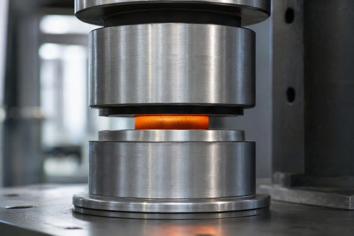
Diffusion welding joins materials by controlling what happens across an entire interface. Instead of creating a weld pool, the process brings prepared surfaces into close contact under heat and pressure, then holds them long enough for deformation, creep, and atomic transport to establish a metallurgical bond.
It is not a furnace recipe in which any two polished parts will bond at one standard temperature and pressure. The material pair, oxide chemistry, surface preparation, atmosphere, tooling, temperature, pressure, and time interact. A process window that succeeds for one alloy, thickness, or stack design may fail when any of those conditions changes.
The method is especially useful for broad-area joints, stacked sheets, laminated structures, and components containing passages that become inaccessible after assembly. Filler-free construction, dimensional precision, limited bulk deformation, high strength, and leak tightness are achievable outcomes—not guarantees.
What diffusion welding is—and what the name means
Diffusion welding is a joining process in which atomic transport across contacting interfaces is the principal bond-forming mechanism. In its conventional form, the parent materials remain solid: there is no bulk melting at the joint and no weld pool that must solidify.
“Diffusion welding” and “diffusion bonding” are generally used interchangeably in current technical and commercial writing. Both describe prepared surfaces held together under elevated temperature and pressure so that intimate contact develops and atoms migrate across the original boundary. TWI classifies diffusion bonding as a solid-state process applicable to similar and dissimilar materials and notes that compatible similar-material joints can be autogenous, without filler metal (TWI’s diffusion-bonding process description).
The terminology has not always been uniform. An SAE technical review published in 1964 observed that many techniques had been called diffusion welding even though it was difficult to determine which processes truly belonged in that category (SAE’s review of diffusion-welding terminology). Ambiguity still arises when sources group fully solid-state diffusion welding with related processes that intentionally form a temporary liquid at the interface.
For clarity, conventional diffusion welding in this article means the fully solid-state process. The parent materials do not undergo bulk melting, and the joint develops through close contact, local deformation, creep, diffusion, and continuing interface evolution.
That distinguishes it from fusion welding. In fusion welding, a liquid phase forms at the joint and then solidifies. The heat source may be an arc, laser, electron beam, or another concentrated source, but melting and solidification are central to the process. Conventional diffusion welding instead heats the interface more uniformly and uses external pressure to establish and preserve contact between solid surfaces.
Solid-state joining is still welding. Diffusion welding, friction welding, forge welding, and other solid-state methods demonstrate that a joint can form without a bulk liquid phase.
For compatible similar materials, diffusion welding can be autogenous: the mating materials themselves form the joint, ordinarily without filler. That can be valuable where filler would add weight, change local chemistry, obstruct a small channel, or introduce another material into a corrosive or high-temperature environment. Dissimilar or difficult combinations may need an engineered interlayer, but an interlayer is an option rather than a defining feature of the process.
How a diffusion-welded bond develops at the interface
Two surfaces that look flat to the eye do not initially contact each other across their full nominal area. At microscopic scale, each contains peaks, valleys, machining marks, waviness, and local thickness variations. Initial contact occurs mainly at projecting asperities. Voids remain between those contact points, while oxide films, adsorbed material, oil, polishing residue, or other contamination may separate the underlying materials.
Bond development therefore begins with creating contact, not with diffusion through an already closed plane.
When pressure is applied, the highest asperities carry a disproportionate share of the load. Local stress deforms those peaks and increases the true area of contact. Elevated temperature lowers resistance to deformation and makes time-dependent mechanisms such as creep more active. The surfaces settle toward each other while the applied load maintains contact.
The process can be understood as a sequence:
- Initial asperity contact: Only part of the nominal interface touches.
- Local deformation: Pressure flattens or deforms high points and increases intimate contact.
- Interface-film management: Surface preparation, deformation, atmosphere control, and material chemistry must disrupt, dissolve, disperse, or otherwise manage oxides and contaminants.
- Void shrinkage: Creep and mass transport reduce the size and number of interfacial cavities.
- Atomic transport: Atoms cross the original interface and establish metallurgical continuity.
- Interface evolution: Continued holding can change pore shape, grain-boundary geometry, phase distribution, composition gradients, and the properties of the original bond line.
Pressure is essential, but pressure alone does not create a complete metallurgical joint. It establishes and maintains the close contact needed for the bond-forming mechanisms to operate. Cold pressing two contaminated plates may increase mechanical contact without producing adequate atomic bonding. Likewise, heating poorly fitted or oxidized surfaces without sufficient load may leave large areas separated.
Temperature has a particularly strong effect because diffusion is thermally activated. A change in bonding temperature can substantially alter the rate of atomic movement and the interface evolution achieved during a fixed hold. Temperature and time therefore cannot be selected independently. A shorter, hotter cycle and a longer, cooler cycle will not necessarily produce equivalent microstructures, especially where grain growth, oxide behavior, creep, phase transformation, or intermetallic formation is involved.
Smoothness helps by reducing the initial height and volume of interfacial gaps. Flatness and thickness control help distribute pressure across more of the assembly. Polishing, however, is not a substitute for chemical control. Aluminum alloys are a familiar example because their persistent surface oxide can make direct metallic contact difficult.
A finished interface should not automatically be described as invisible, pore-free, or identical to the parent material. Depending on the materials and cycle, the original boundary may remain detectable through residual pores, grain structure, composition gradients, oxide remnants, intermetallic phases, or local hardness changes. The relevant question is whether the joint meets its specified mechanical, dimensional, thermal, corrosion, and leak-performance requirements.
The process variables that must work together
Diffusion welding should be developed around seven linked variables rather than one “correct setting.”
1. Material pair
Start with the exact alloys, product conditions, coatings, and heat treatments—not broad labels such as “stainless steel” or “aluminum.” Alloying elements influence melting temperature, oxide stability, diffusivity, high-temperature strength, creep behavior, phase formation, and sensitivity to thermal exposure.
Similar materials are often easier to evaluate because they usually have compatible thermal-expansion behavior and do not create a new dissimilar-metal reaction zone. They can still present oxide, flatness, contamination, or grain-growth problems.
Dissimilar combinations add the possibility of unequal deformation, diffusion imbalance, brittle compounds, and thermal-expansion mismatch.
2. Homologous temperature
Temperature is commonly expressed as a fraction of the material’s absolute melting temperature, using a temperature scale that begins at absolute zero. General educational guidance places solid-state diffusion bonding at approximately 50% to 90% of the parent material’s absolute melting temperature (University of Cambridge overview of solid-state diffusion bonding).
Other sources and facilities report narrower ranges. TWI, for example, describes approximately 50% to 80% as typical while noting that its own equipment tends to operate around 70% to 90% because of furnace load limitations. These are orientation ranges, not interchangeable production specifications.
A given Celsius temperature represents a very different thermal condition for a low-melting alloy than for a refractory metal.
The selected temperature must make deformation, creep, and diffusion active enough to create the bond while avoiding unacceptable softening, grain growth, phase transformation, coating damage, reaction-layer growth, or loss of dimensional control.
3. Applied pressure
Pressure brings the surfaces into intimate contact, deforms asperities, and maintains contact as voids shrink. The required value depends on material strength at temperature, part geometry, surface condition, tooling stiffness, available force, and permitted deformation.
There is no universal pressure value. A load that is inadequate for one alloy may excessively deform another. Total machine force also rises with bond area, so even moderate nominal pressure can demand substantial equipment capacity when applied across a large stack.
Uniformity matters as much as the nominal setting. Platen misalignment, tooling deflection, stack-thickness variation, local stiffness, and thermal gradients can create overloaded and underloaded regions in the same assembly.
4. Holding time
Reported bonding times range from a few minutes to a few hours, depending on the material system and process conditions. The required duration depends on how quickly intimate contact develops, how interfacial pores evolve, how far relevant atoms must move, and whether reaction layers form.
Commercial diffusion welding is commonly batch-oriented. Total furnace occupancy includes atmosphere preparation or evacuation, heating, temperature stabilization, the bonding hold, and controlled cooling—not merely the time at the peak setting.
Longer is not automatically better. Additional time may improve pore closure in one system while causing excessive creep, grain growth, intermetallic thickening, or loss of heat-treated properties in another.
5. Surface roughness and flatness
Mating faces should be smooth, flat, dimensionally consistent, and closely fitted. Roughness increases the initial void volume. Poor flatness can prevent large regions from contacting until the stack deforms, while sheet-thickness variation can concentrate load on only a few layers.
A roughness number alone does not describe waviness, edge burrs, embedded abrasive, or local thickness errors. Surface requirements should be tied to the complete manufacturing route and verified on representative parts.
Overfinishing is not necessarily beneficial. It can add cost or leave polishing residue without resolving oxide or contamination problems.
6. Cleanliness and oxide condition
Cleaning must remove substances that block metallic contact or react unfavorably during the thermal cycle. Machining lubricant, fingerprints, polishing compound, moisture, loose particles, and cleaning residue can all compromise an interface.
Oxide control is material-specific. Some films may fracture under deformation, dissolve, become unstable at bonding temperature, or be managed with an interlayer. Others remain stable and continuous. Cleaning immediately before assembly may still be ineffective if the surface rapidly reoxidizes or becomes contaminated during handling.
A qualified procedure should therefore address preparation, rinsing or drying where applicable, handling, storage, assembly delay, and protection of the prepared surfaces.
7. Atmosphere
The atmosphere must limit oxidation and contamination throughout heating and holding. Vacuum is common, but controlled inert or partial-pressure atmospheres may be suitable where compatible with the materials and equipment.
Atmosphere quality is more than the name of the gas. Residual oxygen, moisture, leaks, furnace cleanliness, tooling outgassing, purge practice, and time at temperature can all affect the interface. “Argon” by itself is not a complete process specification.
| Variable | Purpose | Too low or inadequate | Excessive or poorly controlled | Qualification question |
|---|---|---|---|---|
| Material compatibility | Establish a bondable chemical and mechanical system | Low mutual diffusion, persistent films, or a weak interface | Excessive reaction or unwanted phase formation | What phases, gradients, and property changes occur in the proposed pair? |
| Homologous temperature | Activate deformation, creep, and atomic transport | Slow contact development and retained voids | Grain growth, softening, distortion, or reaction-layer growth | What range produces an acceptable bond without damaging the materials? |
| Applied pressure | Create and maintain intimate contact | Isolated contact, unbonded regions, or retained pores | Bulk deformation, channel collapse, tooling imprint, or extrusion | How much pressure is needed, and how uniformly can the tooling apply it? |
| Holding time | Permit pore shrinkage and interface evolution | Incomplete diffusion or inadequate bonded area | Excessive furnace occupancy, creep, grain growth, or brittle-phase growth | What is the shortest validated hold that consistently meets requirements? |
| Roughness and flatness | Minimize gaps and distribute load | High initial void volume and uneven contact | Unnecessary finishing cost or embedded residue without better oxide control | Which finish, flatness, and thickness tolerances are necessary and measurable? |
| Cleanliness and oxide condition | Expose and preserve bondable surfaces | Contamination or stable films isolate the materials | Aggressive preparation may alter dimensions or roughen surfaces | How will surfaces be prepared, handled, stored, and assembled reproducibly? |
| Atmosphere | Limit oxidation and hot contamination | Oxide growth, moisture exposure, or furnace contamination | An incompatible vacuum or gas environment may affect materials, tooling, or equipment | What vacuum level, gas purity, purge method, and leak condition are required? |
A usable process window must be developed and validated for the exact grades, dimensions, tooling, atmosphere, heating profile, pressure history, and required properties. Broad handbook ranges are useful for feasibility work, but they should not be copied directly into a production traveler.
Equipment, loading, heating, and atmosphere control
A representative commercial uniaxial diffusion-welding system combines:
- a sealed vacuum or controlled-atmosphere chamber;
- a furnace or another controlled heat source;
- hydraulic rams or an equivalent loading system;
- platens, dies, or graphite tooling;
- force-transmission components that carry load into the assembly;
- temperature, displacement, force, and atmosphere monitoring; and
- cooling and handling provisions suited to the thermal cycle.
The tooling does more than hold the work. It must transmit pressure uniformly, remain stable at temperature, accommodate thermal expansion, avoid contaminating the component, and protect delicate internal features from collapse. For multilayer stacks, tooling also preserves alignment while the assembly heats, creeps, and cools.
TWI describes commercial uniaxial equipment as a vacuum furnace with hydraulic rams applying pressure through graphite tooling. It reports operation below 1 × 10⁻² mbar as typical of its process description—not as a universal requirement for every material or facility (TWI’s commercial uniaxial diffusion-bonding description).
Vacuum is common because diffusion welding keeps components hot for an extended period. Reducing available oxygen and contaminants helps limit continued oxidation of the faying surfaces and reduces the likelihood that furnace gases will interfere with the interface.
Vacuum is not mandatory in every case. TWI reports the use of partial-pressure argon or nitrogen for some materials incompatible with high vacuum, while the University of Cambridge also identifies dry nitrogen, argon, and helium as possible controlled atmospheres. Gas selection must account for material reactivity, purity, moisture, tooling, and furnace design.
There is also a limited exception for air bonding. Metals whose oxide films become thermodynamically unstable at bonding temperature may sometimes be joined in air; silver is a commonly cited example. This should not be interpreted as evidence that air is a normal atmosphere for diffusion welding, particularly for oxide-sensitive materials.
Heating may be supplied by resistance-heated furnaces, induction systems, or other equipment capable of controlling the component’s thermal profile.
Equipment feasibility therefore depends on more than whether the part fits through the chamber door. Important constraints include:
- usable chamber dimensions;
- maximum available force at bonding temperature;
- loaded platen area;
- tooling height and stiffness;
- alignment under load;
- pressure distribution across the interface;
- heating and cooling uniformity;
- vacuum or gas-system capacity;
- thermocouple placement and control accuracy; and
- support for the assembly without crushing channels or distorting thin sheets.
Large bond areas are particularly demanding. Required machine force increases with area, while tooling deflection, accumulated thickness variation, and thermal gradients make uniform conditions harder to maintain. No single dimensional limit applies because equipment architecture, material strength, component geometry, and allowable deformation differ.
Alternative loading strategies are also being investigated. A research apparatus reported in 2023 combined a vacuum process chamber, induction heating, force-transmission components, cooling hardware, and cyclically pulsative loading (documented pulsative-force diffusion-welding apparatus). The available evidence establishes the equipment concept but does not show that pulsating force improves strength, reduces porosity, or shortens the cycle compared with constant loading.
Materials, interlayers, and the challenge of dissimilar joints
Diffusion welding has been applied to similar and dissimilar metals and to selected ceramics and composites. Reported examples include aluminum and titanium alloys, steels, nickel alloys, copper and zirconium alloys, silicon carbide, silicon nitride, and metal-matrix composites (TWI’s reported diffusion-bonding material range).
That list demonstrates prior experience; it is not a universal compatibility chart. “Can be diffusion welded” is incomplete unless it identifies the exact grades, product forms, surface conditions, atmosphere, cycle, joint design, and acceptance requirements.
Compatible similar materials may often be joined directly. With no filler, bond-line chemistry is not intentionally changed by a third metal. Surface oxides, coatings, segregated alloying elements, heat-treatment condition, and grain structure can still influence the result.
Dissimilar joints require a more deliberate compatibility assessment. Principal risks include:
- Low mutual diffusivity: Bond development may be too slow within an acceptable thermal cycle.
- Stable oxides: The underlying materials may remain chemically isolated.
- Thermal-expansion mismatch: Unequal expansion and contraction can generate stress during heating, cooling, or service.
- Unequal high-temperature strength: One material may deform well before the other establishes adequate contact.
- Brittle intermetallic formation: Diffusion and reaction can create hard, low-ductility phases.
- Diffusion imbalance: Unequal atomic fluxes may contribute to composition gradients or pore development.
- Service incompatibility: A joint that survives manufacturing may still perform poorly under fatigue, corrosion, thermal cycling, or sustained high temperature.
Aluminum illustrates the oxide problem. Its stable surface film can prevent direct metal-to-metal contact even when the selected heat and pressure would otherwise promote deformation and diffusion. Successful bonding may require tightly controlled surface preparation, a short delay before protected assembly, suitable atmosphere management, or a specially designed interlayer.
An interlayer is a material intentionally placed between the components. It is not simply conventional fusion-welding filler, and it does not guarantee a sound joint.
Interlayer composition and thickness must be engineered because the interlayer changes bond-line chemistry. It may introduce compounds, composition gradients, melting behavior, corrosion response, or thermal-expansion effects that are absent from a direct joint.
Aluminum-copper cautionary case
In one experiment, nominally pure aluminum and copper bars were diffusion welded in argon at 560 °C under 4.5 N/mm² for a 60-minute hold. Three diffusion-welded specimens averaged 60.80 N/mm² in tensile strength and fractured with brittle behavior near the welding zone. The researchers associated Al₂Cu, AlCu, and Al₄Cu₉ intermetallic phases with joint behavior (aluminum-copper diffusion- and friction-welding comparison).
This is a cautionary case, not a recommended process schedule. Its outcome applies only to the reported compositions, bar geometry, preparation, atmosphere, heating history, load, and hold time. Different interface treatments, interlayers, equipment, or process windows could produce different results.
The useful lesson is not that aluminum and copper cannot be diffusion welded. The pair was joined, but joint formation alone did not ensure desirable mechanical behavior. Reaction-layer composition, thermal history, oxide condition, and interface integrity had to be controlled alongside contact and diffusion.
Why manufacturers use diffusion welding
The strongest case for diffusion welding is often geometric rather than procedural. The method can bond broad interfaces and multiple stacked layers at once, including surfaces that will be unreachable after assembly.
Consider a compact heat exchanger made from patterned shims:
- Channels, headers, ports, or cavities are machined, etched, stamped, or otherwise formed in individual sheets.
- The sheets are cleaned, aligned, and stacked in the required sequence.
- Tooling supports the stack and applies load without collapsing its internal features.
- Diffusion welding joins the sheet-to-sheet interfaces.
- The bonded stack becomes an integrated component containing sealed internal flow paths.
No torch, electrode, or filler-delivery tool has to enter each internal channel. Joining occurs across the prepared faces of the stack. This workflow can be adapted to microchannel heat exchangers, cold plates, laminated filters, layered structures, thin-foil honeycombs, and cavity-containing trays. Commercial manufacturing examples include photo-etched sheets stacked into cooling components, filters, and laminated cavity structures (examples of diffusion-bonded laminated products).
For a compatible similar-material assembly, filler-free construction offers several potential benefits. It does not add filler-material weight, and it avoids creating a galvanic couple solely because a compositionally different filler was introduced. That does not make the component immune to corrosion. Performance still depends on the base alloy, environment, temperature, flow chemistry, surface condition, and any changes produced at the bond line.
Another attraction is limited bulk deformation relative to processes that melt or heavily forge the joint region. Properly supported parts can retain fine internal geometry and close dimensional relationships. The applied pressure is real, however: thin walls, unsupported channels, soft alloys, or poorly designed tooling can still deform.
High-strength and leak-tight joints are legitimate design goals where the interface, tooling, and process have been qualified. They are not automatic properties of the process name. A component intended to contain pressure or isolate fluids requires explicit mechanical and leak criteria, followed by validation appropriate to its geometry and service.
Reported application areas include:
- aerospace layered and high-value structural components;
- electronic cooling hardware;
- semiconductor-manufacturing equipment;
- medical-device components;
- microfluidic assemblies;
- compact heat exchangers;
- selected nuclear-related components; and
- difficult-to-machine structures with enclosed passages.
These examples show where diffusion welding has been used, not where any diffusion-welded part is automatically acceptable. Aerospace, medical, semiconductor, or nuclear service brings application-specific requirements for materials, cleanliness, traceability, inspection, and qualification.
The process tends to make the most technical and economic sense when a part has high value, broad interfaces, demanding precision, inaccessible internal features, or a material combination that is difficult to join another way. It is rarely a general replacement for fast, accessible shop welds on ordinary fabrication.
Limitations, defects, and misleading quality claims
Diffusion welding can fail even when the furnace reaches its programmed temperature and the press records the intended force. Machine settings do not reveal everything happening across a buried interface.
Common failure modes and concerns include:
- incomplete bonding;
- residual interfacial voids;
- oxide remnants;
- contamination trapped at the interface;
- locally unbonded areas caused by thickness variation;
- channel collapse or bulk distortion;
- excessive grain growth;
- undesirable phase transformation;
- brittle intermetallic layers;
- cracking related to thermal mismatch;
- nonuniform properties across a large bond area; and
- loss of prior heat-treated properties during the thermal cycle.
Stable oxide films and contamination are especially deceptive. Parts may be flat, hot, and heavily loaded while a thin nonmetallic barrier still separates the underlying materials. More temperature or time does not necessarily solve that problem. It may instead thicken reaction layers, soften the component, or damage its microstructure.
Large assemblies add scale-up challenges. Heating uniformity becomes harder to maintain, while total force, platen deflection, tooling creep, and accumulated sheet-thickness variation affect pressure distribution. A successful coupon process may not transfer directly to a full-area component even when the nominal temperature, pressure, and hold time remain unchanged.
Production constraints also matter:
- heating and cooling may occupy the furnace for long periods;
- the process is commonly batch-oriented;
- vacuum and hot-loading equipment require capital and maintenance;
- preparation and clean handling can be labor-intensive;
- tooling may be component-specific;
- chamber size constrains the work envelope;
- available machine force constrains the loaded area; and
- process qualification and inspection add cost and lead time.
Avoid categorical claims such as “always void-free,” “no residual stress,” or “as strong as the parent metal.” Low porosity, limited distortion, reduced residual stress, and parent-material-like properties may be achieved in suitable systems. They remain conditional on material compatibility, thermal history, pore closure, phase formation, geometry, and validation.
Visual appearance is particularly weak evidence. In the aluminum-copper experiment described earlier, the diffusion-welded area had a smooth exterior, yet its average tensile strength was below the reported strength of the pure aluminum, and fracture occurred near the welding zone with brittle behavior. A smooth perimeter did not establish complete bonding or parent-material performance.
Engineering drawings and procedures should define what the joint must do. Depending on the component, requirements may include:
- minimum mechanical properties;
- maximum allowable unbonded area;
- leak-rate limits;
- channel dimensions and tolerances;
- pressure resistance;
- fatigue or thermal-cycle performance;
- acceptable bond-line phases or hardness;
- corrosion performance;
- final heat-treatment condition; and
- traceability of preparation and furnace records.
The available evidence does not establish one universal inspection method, welding code, or defect threshold for every diffusion-welded component. Inspection and test methods must be selected and validated for the particular material, thickness, joint geometry, service requirement, and defect type. No single method should be promised to find every possible bond-line defect.
Inspection planning should begin during design. A multilayer component may contain extensive buried interfaces that are difficult to access after bonding. Qualification may therefore require representative coupons, process monitoring, destructive examination during development, and application-specific final testing rather than reliance on visual inspection alone.
Diffusion welding versus brazing, fusion welding, friction welding, and TLP bonding
Process selection should begin with the materials, geometry, required properties, and production constraints—not with a general ranking of joining methods.
| Process | Does the parent material melt? | Filler or interlayer | Is external pressure normally required? | Geometry fit | Cycle-time tendency | Principal interface risks |
|---|---|---|---|---|---|---|
| Conventional diffusion welding | No bulk melting | Usually none for compatible similar materials; optional interlayer for difficult pairs | Yes | Broad prepared interfaces, stacked layers, laminations, and enclosed channels | Often long and batch-oriented | Oxides, contamination, residual voids, uneven contact, distortion, and intermetallics |
| Brazing | Base materials remain solid; filler melts | Brazing filler is required | Usually not in the diffusion-welding sense | Gaps, lap joints, irregular surfaces, and distributed joints | Often more adaptable to production flow | Poor wetting, inadequate capillary flow, residue, filler incompatibility, voids, and corrosion |
| Fusion welding | A liquid phase forms and solidifies at the joint | May be autogenous or use filler | Not generally required for bond formation | Accessible seams, edges, grooves, and localized joints | Depends strongly on process and part | Solidification defects, heat-affected-zone changes, distortion, cracking, and dilution |
| Friction welding | Normally solid-state at the interface | Usually none | Axial or forging force is integral | Machine-compatible interfaces; geometry depends on the friction-welding variant | Process-specific; shorter than diffusion welding in the cited aluminum-copper experiment | Upset, flash, alignment, interface heating, geometry limits, and dissimilar-metal reactions |
| Transient-liquid-phase bonding | A temporary interfacial liquid intentionally forms | Usually uses an engineered interlayer or local composition that produces the liquid | May require less pressure than fully solid-state bonding | Broad interfaces and selected difficult material systems | May still require an extended thermal hold | Incomplete isothermal solidification, segregation, residual brittle phases, and interlayer nonuniformity |
Diffusion welding versus brazing
Brazing joins parts by melting a filler metal above 450 °C but below the melting points of the base materials. The liquid filler moves through a suitably designed joint by capillary action. Conventional diffusion welding ordinarily remains fully solid-state, applies pressure, and does not require filler for compatible similar materials (comparison of diffusion bonding and brazing fundamentals).
Brazing may be the better fit when an assembly contains controlled gaps, irregular surfaces, varied joint orientations, or geometry that cannot be loaded uniformly. Filler can accommodate some fit-up variation that would prevent intimate solid-state contact in diffusion welding. Brazing can also be easier to adapt to some production arrangements.
Diffusion welding may be preferable for prepared broad interfaces, high-precision laminations, very small internal channels, or assemblies where adding conventional filler is undesirable. Its dependence on close fit, clean surfaces, and applied load makes it less forgiving of uncontrolled gaps.
Neither process is universally stronger, cheaper, or more reliable. A brazed joint depends on filler selection, clearance, wetting, atmosphere or flux, base-material compatibility, and service conditions. A diffusion-welded joint depends on contact, oxide control, diffusion behavior, pressure uniformity, and thermal exposure.
Diffusion welding versus fusion welding
The category-level difference is melting. Fusion welding creates a liquid phase that later solidifies. Conventional diffusion welding avoids bulk melting and develops the joint between solid surfaces.
Avoiding a weld pool removes solidification from the bond-forming sequence and can help preserve delicate stacked geometry. Diffusion welding, however, exposes a larger assembly to an extended thermal cycle and requires loading equipment.
Diffusion welding versus friction welding
Both processes can operate without bulk melting, but their mechanisms and geometry differ. Friction welding generates interface heat through relative motion and applies forging force. It may produce upset or flash and requires geometry compatible with the selected friction process.
In the reported aluminum-copper experiment, friction welding was faster and produced stronger specimens than the tested diffusion-welding schedule, but it also caused substantial upset on the aluminum side (reported aluminum-copper friction and diffusion comparison). This is a bounded comparison between specific materials, specimens, and settings—not proof that friction welding is generally superior.
Selection therefore involves more than tensile strength. A designer must consider whether rotational or other relative motion is possible, whether upset can be tolerated, whether internal features must remain aligned, and whether the interface can be accessed and loaded by the machine.
Conventional diffusion welding versus TLP bonding
Transient-liquid-phase bonding, or TLP bonding, should not be treated as identical to conventional fully solid-state diffusion welding. TLP intentionally creates a temporary liquid at the interface. As a melting-point-depressing solute diffuses into the base materials, the liquid solidifies isothermally—at the bonding temperature rather than through ordinary cooling from a weld pool.
The temporary liquid can improve interface contact or assist oxide disruption and may reduce the pressure required. The result depends heavily on interlayer chemistry, diffusion behavior, and completion of isothermal solidification.
If a specification prohibits any liquid formation, TLP is not simply another setting for conventional diffusion welding. Conversely, where fully solid-state contact is difficult, a carefully engineered TLP system may be worth evaluating.
A practical decision workflow
Use the following sequence when deciding whether diffusion welding belongs on the shortlist:
- Define the exact material pair. Identify alloy grades, product condition, coatings, heat treatment, and the weaker material at bonding temperature.
- Assess the oxide problem. Determine whether the surfaces can be made and kept bondable through preparation, atmosphere control, deformation, or an interlayer.
- Review geometry and access. Decide whether broad interfaces, stacked layers, or sealed internal passages justify whole-area bonding.
- Set property requirements. Define strength, leak performance, dimensions, corrosion behavior, fatigue life, and thermal requirements before selecting parameters.
- Establish acceptable deformation. Consider channel collapse, thickness change, tooling imprint, edge extrusion, and final machining allowance.
- Evaluate cycle time and volume. Include preparation, loading, evacuation or purging, heating, holding, cooling, unloading, inspection, and rework—not just the peak hold.
- Confirm equipment capacity. Check chamber envelope, available force, tooling stiffness, temperature uniformity, atmosphere quality, and monitoring.
- Develop and qualify the process. Use representative materials and geometry, then verify that the resulting joint consistently meets defined acceptance criteria.
Diffusion welding is best understood as a specialized interface-engineering process, not as a generic combination of furnace temperature and press force. It is most compelling when a component requires broad-area bonding, stacked layers, close dimensional control, or sealed internal passages.
Those benefits depend on a qualified combination of material compatibility, oxide control, preparation, heat, pressure, time, atmosphere, tooling, and inspection requirements. The correct starting point is the material pair and the properties the finished component must deliver—not a generic temperature or pressure.
Frequently asked questions about diffusion welding
Are diffusion welding and diffusion bonding the same process?
Generally, yes. Technical and commercial sources commonly use “diffusion welding” and “diffusion bonding” interchangeably for joining driven principally by atomic transport across an interface.
Terminology becomes less consistent when fully solid-state bonding is grouped with related processes that form a temporary liquid. When the distinction matters, specify conventional solid-state diffusion welding or name the particular variant, such as transient-liquid-phase bonding.
What temperature is used for diffusion welding?
General guidance places solid-state bonding at roughly 50% to 90% of the material’s absolute melting temperature (University of Cambridge diffusion-bonding guidance). Individual facilities and material systems may use narrower ranges.
That percentage is not a production recipe. The correct temperature must be developed for the exact alloy pair and must activate bonding without causing unacceptable distortion, grain growth, phase transformation, intermetallic growth, or loss of required properties.
Does diffusion welding always require a vacuum?
No. Vacuum is common because it helps limit oxidation and contamination during prolonged heating. Controlled inert or partial-pressure atmospheres may also be suitable for some materials and equipment arrangements.
A few metals with oxide films that become unstable at bonding temperature may even be bonded in air, but that is a limited exception. Atmosphere selection must be qualified for the materials, tooling, gas purity, moisture level, chamber condition, and thermal cycle.
Does diffusion welding require filler metal?
Not ordinarily for compatible similar-material joints. Those joints can be autogenous, with the parent materials bonding directly.
An engineered interlayer may be used for dissimilar or otherwise difficult combinations. It can assist contact, diffusion, oxide management, or phase control, but it also changes bond-line chemistry. Its composition and thickness must therefore be treated as process variables rather than as a universal remedy.
Is a diffusion-welded joint as strong as the parent metal?
It can approach parent-material strength in a compatible, well-prepared, properly processed, and validated system, but that result is not guaranteed. Residual voids, contamination, oxides, reaction layers, grain growth, thermal mismatch, or brittle phases can make the joint weaker or less ductile.
Strength must be demonstrated for the actual materials, geometry, thermal cycle, atmosphere, and loading condition. External smoothness or a barely visible bond line is not proof of parent-material performance.