
How to Choose, Set Up, and Run 7018 Without Guesswork
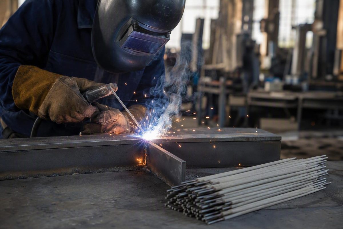
E7018 is a low-hydrogen, iron-powder stick electrode commonly used for carbon steel and selected low-alloy steel work. The familiar designation communicates several useful characteristics, but it does not identify one universal amperage, polarity, storage rule, or approved application.
A reliable setup therefore starts with the exact product—not merely the four-digit classification. Match the electrode diameter, manufacturer’s operating range, supported current type, welding position, joint, material, and power source. For controlled or critical work, the applicable welding procedure and job requirements take priority over general guidance.
This article provides a systematic starting method. It is not a substitute for an electrode data sheet, equipment manual, qualified instruction, or job-specific procedure.
What E7018 Means—and What the Classification Does Not Guarantee
E7018 is a covered electrode for shielded metal arc welding (SMAW), commonly called stick welding. It is generally described as having a low-hydrogen, iron-powder coating.
The designation breaks down as follows:
- E identifies an electrode.
- 70 places it in the 70,000 psi minimum tensile-strength class.
- 1 indicates all-position capability.
- 8 relates to coating, penetration, and permitted current characteristics.
The final digit should not be reduced to a simple polarity instruction. Current compatibility still needs to be confirmed for the specific product. Commercial electrode guidance also associates E7018 with a smooth arc, low spatter, medium penetration, and good deposition, but these are generalized or manufacturer-described characteristics—not independent proof of how every product will perform. A broader stick-electrode classification guide explains the designation and the need to check diameter-specific manufacturer data.
“All position” generally encompasses flat, horizontal, vertical, and overhead welding. It does not by itself establish that unrestricted vertical-down progression is suitable for every E7018 product or job. Use the progression permitted by the selected electrode’s documentation and the applicable procedure.
The “70” is a classification threshold, not a promise that every reported test result will equal exactly 70,000 psi. A specific product may report a higher value without changing the meaning of E7018. For example, Forney lists 84,000 psi for its 3/32-inch item 30705, along with a 65–100 A operating range and DCEP or DCEN polarity. Those figures apply to that item alone. Forney’s product page also warns against using item 30705 with low-open-circuit-voltage power sources.
The E7018 classification alone does not establish:
- Compatibility with every steel grade
- Suitability for every load or service condition
- Approval for a particular structure or pressure boundary
- One universal amperage setting
- Satisfactory operation on every AC welder
- Permission to use any welding progression
- Adequate impact properties for every service temperature
- Compliance with a particular procedure or job specification
Treat the classification as the beginning of electrode selection, not the final decision.
Where E7018 Fits—and Where Electrode Choice Alone Is Not Enough
E7018 is broadly associated with carbon steel and some low-alloy steel work. Seller and manufacturer guidance commonly mentions structural frames, construction frameworks, heavy-equipment components, machinery repair, tanks, restrained joints, and other load-bearing or crack-sensitive fabrication.
Some sellers also market E7018 for shipbuilding, pipelines, pressure-related fabrication, and similar industrial work. Those descriptions identify possible markets; they do not demonstrate that an electrode, procedure, or welder is approved for a particular job.
The low-hydrogen system matters because diffusible hydrogen can be one contributor to hydrogen-assisted cracking. Selecting and correctly handling a suitable low-hydrogen electrode helps control that contributor. It does not eliminate cracking risk or make the rest of the welding system unimportant.
E7018 cannot compensate for:
- Unknown or incompatible base metal
- Unsuitable joint design
- Poor fit-up
- Excessive restraint
- Oil, paint, water, rust, or other contamination
- Incorrect heat input
- Required thermal controls being omitted
- Inadequate fusion
- An unsuitable or unapproved procedure
For ordinary shop work, begin by identifying the material and understanding what the finished part must do. For repairs, consider how the component failed and whether welding is an appropriate repair method. For controlled work, do not infer service approval from an E7018 label or a seller’s application list. Use the consumable, documentation, procedure, and qualifications required for that job.
E7018 versus E6013
Neither classification is universally better.
Commercial comparison guidance generally positions E6013 for thinner steel, light fabrication, general repairs, and easier handling. The same guidance positions E7018 for applications needing a higher minimum tensile-strength class or low-hydrogen consumable control. At the classification level, E6013 is associated with a 60,000 psi minimum tensile-strength class, while E7018 is associated with 70,000 psi. Texas ICO’s comparison also emphasizes that E7018 is more moisture-sensitive.
Strength class is only one selection factor. The two electrodes differ in coating, storage needs, operating behavior, current compatibility, and typical applications. Do not substitute one for the other on controlled work merely because both can be used on some carbon steels.
Choosing 3/32-, 1/8-, and 5/32-Inch E7018
Select the diameter by considering:
- Joint type and required bead size
- Material thickness
- Welding position
- Available machine output
- Machine duty cycle
- Procedure or heat-input limits
- Fit-up and access
- The selected product’s operating range
A smaller rod is not automatically suitable for sheet metal, and a larger rod is not automatically the best choice for thick plate. The electrode has to suit both the joint and the power source.
- 3/32 inch: A lower-current option often marketed for thinner material and out-of-position work. Its smaller puddle may be easier to manage, but that does not automatically make E7018 suitable for very thin sheet.
- 1/8 inch: A common general-purpose size. It offers useful deposition without the output demands of larger rods, although published ranges still vary materially by product.
- 5/32 inch: A higher-current option commonly marketed for heavier work. Machine capacity, duty cycle, position, and puddle control become increasingly important.
The following figures are source-specific rather than universal:
| Diameter | Examples of seller-described use | Hobart approximate range | Other published product ranges | Checks before welding |
|---|---|---|---|---|
| 3/32 in | Thinner material; vertical or overhead work | 80–100 A | PGN: 80–110 A; Forney item 30705: 65–100 A | Product polarity, machine compatibility, low-end arc stability, position |
| 1/8 in | General fabrication and repair | 90–150 A | PGN: 110–160 A | Position, joint size, available output, duty cycle |
| 5/32 in | Thicker or heavy-duty work | 110–230 A | PGN: 150–210 A | Output capacity, duty cycle, lead condition, position, puddle control |
The Hobart values are approximate manufacturer-family guidance rather than one procedure for all E7018 products. Hobart publishes 80–100 A for 3/32 inch, 90–150 A for 1/8 inch, and 110–230 A for 5/32 inch.
PGN’s commercial product guidance differs: 80–110 A, 110–160 A, and 150–210 A for the same three sizes. PGN also describes 3/32 inch as suitable for thinner or out-of-position work, 1/8 inch as general purpose, and 5/32 inch as intended for heavier work.
Those differences are the lesson. Diameter alone does not determine the setting. Brand, formulation, position, joint, and machine behavior all matter.
A practical buying sequence is:
- Identify the required electrode classification and any supplementary designators.
- Choose a diameter that fits the joint and position.
- Confirm the exact product’s supported current type and polarity.
- Compare its operating range with the welder’s output and duty cycle.
- Check any product-specific power-source limitation.
- Confirm that the package condition and documentation are suitable for the work.
If the machine cannot comfortably support the selected rod, use a smaller diameter, another suitable product formulation, or a different process only when the job permits that change.
Amperage, Polarity, AC Compatibility, and Arc Force
A broad cross-source starting envelope is approximately:
- 3/32 inch: 60–110 A
- 1/8 inch: 80–160 A
- 5/32 inch: 110–230 A
These envelopes combine published guidance for different products and positions. They are useful for orientation, not as welding procedures. The exact product’s package or data sheet should set the working boundaries.
Position changes the useful current range
Vertical and overhead welding often use lower settings than flat or horizontal welding because puddle control becomes more difficult. One commercial guide gives the following typical—not universal—ranges:
| Diameter | Flat or horizontal | Vertical or overhead |
|---|---|---|
| 3/32 in | 70–110 A | 60–70 A |
| 1/8 in | 100–140 A | 80–110 A |
| 5/32 in | 140–170 A | 130–150 A |
These values come from commercial guidance and should not override product data. YesWelder publishes these position-specific ranges while noting that actual settings depend on the manufacturer and application.
Use the table to understand the direction of adjustment, not to prescribe a setting. Begin inside the selected product’s permitted range and tune in small steps while observing puddle support, toe wash, and arc stability.
DCEP, DCEN, and AC in plain language
- DCEP means direct current electrode positive. The electrode holder connects to the positive terminal and the work lead to the negative terminal.
- DCEN means direct current electrode negative. The electrode holder connects to the negative terminal and the work lead to the positive terminal.
- AC means alternating current. Current direction reverses repeatedly, so there is no fixed electrode-positive connection.
Identify the connection from the welder’s terminal markings and manual rather than cable color alone. Follow the equipment manufacturer’s instructions before changing lead connections.
DCEP is commonly favored in practical guidance, but E7018 polarity support is product-specific. Hobart’s general technical article discusses AC, DCEP, and DCEN operation. The Forney product described earlier lists DCEP and DCEN but does not list AC. Other E7018 products are specifically sold for AC and DCEP.
Therefore, an E7018 label does not guarantee satisfactory operation on every AC machine. Before purchasing rods for a small transformer or hobby welder, check:
- Whether the exact electrode supports AC
- The diameter-specific current range
- Any stated open-circuit-voltage limitation
- The welder’s output and duty cycle
- The welder manual and terminal arrangement
- The electrode package or manufacturer data sheet
A machine may show enough amperage on its control panel yet still be a poor match for a product with additional power-source requirements.
What arc force does
Arc force, arc control, and dig are common names for a machine feature that temporarily adds current as the arc becomes very short. The feature can help resist sticking and maintain the arc, but excessive intervention can make E7018 feel harsh and unstable.
One welding author suggests 30–60% as a practical starting region for many E7018 applications. This is not a transferable specification: machine scales and control logic differ. Weldmonger’s guide recommends beginning conservatively and increasing arc force gradually.
Use observable behavior rather than the percentage alone:
- Too little effective current or arc force: repeated sticking, arc outages, or a narrow and humped bead
- Too much current or aggressive arc force: harsh arc, extra spatter, unstable puddle, runoff, erratic profile, or undercut
Do not use arc force to hide incorrect polarity, poor work-lead contact, an unsuitable amperage setting, or an electrode in questionable condition. Change one variable at a time.
Technique for Flat, Horizontal, Vertical-Up, and Overhead Welds
The central technique rule for E7018 is to maintain a tight, controlled arc. Excessive arc length makes the puddle harder to manage and may contribute to unstable shielding or porosity. Use steady travel and restrained manipulation rather than whipping the electrode as though it were a cellulosic rod.
Before practicing, confirm the product and polarity, use clean practice steel, establish a sound work connection, and select a dry electrode with intact flux. Keep adjustments inside the manufacturer’s published range.
Flat welding
Maintain a short arc and use a steady drag or near-neutral travel angle appropriate to the joint. Watch the leading edge of the puddle and both toes rather than judging only the solidified bead.
Hobart’s manufacturer guidance recommends a flat or horizontal bead width near 2.5 times the core-wire diameter. Treat that as technique guidance, not as a universal acceptance criterion.
For a fillet weld, monitor both legs and the root area. Remove the slag and inspect the bead before changing settings.
Horizontal welding
Use the same tight arc, but account for the puddle’s tendency to sag toward the lower member. Avoid excessive dwell at the lower toe.
Start with a stringer or restrained movement. If the upper toe is not washing in, first examine arc length, work angle, current, and travel speed rather than immediately widening the weave.
Vertical-up welding
Progress upward with a tight arc and controlled pauses that allow the puddle to establish at the toes. Hobart suggests a 3–5 degree leading angle and a bead width around 2.5–3 times the core-wire diameter for vertical-up work.
A straight progression or slight, controlled side-to-side movement may be appropriate depending on the joint and procedure. Do not treat a wide weave as the default.
Field advice in an AWS-hosted forum clusters around 115–125 A for some 1/8-inch E7018 vertical-up setups, together with DCEP, a short arc, and limited manipulation. That is anecdotal experience tied to particular machines and workpieces—not an AWS standard or qualified setting. The discussion also shows how changing polarity and plate thickness changed the reported result.
Tune your progression by watching:
- Whether the puddle remains supported
- Whether each toe washes in before you move
- Whether the center fills without becoming excessively convex
- Whether slag remains behind the arc
- Whether the bead piles up or begins to run
Overhead welding
Keep the puddle small and the arc tight. A setting toward the lower part of the product’s permitted positional range may improve control, but current still has to be sufficient to avoid a cold, rope-like bead.
Use restrained movement unless the applicable procedure calls for something else. Arrange the work and your position according to site requirements, and use the required protective equipment and ventilation. Equipment instructions and approved procedures override general technique advice.
Three worked starting setups
These examples illustrate setup logic for practice. They are not production procedures.
Example 1: 3/32-inch practice bead
- Use clean practice plate suitable for the intended current.
- Select a dry 3/32-inch E7018 with intact coating.
- Confirm the product’s current type, polarity, and operating range.
- If the package lists approximately 70–100 A, begin near the middle rather than assuming one universal setting.
- Verify the work connection and maintain a tight arc.
- Adjust in small increments for sticking, puddle support, and toe wash.
Example 2: 1/8-inch flat weld
- Prepare clean practice steel and an appropriate joint.
- Confirm electrode condition, listed polarity, and work-lead contact.
- For a product following Hobart’s approximate guidance, work within its 90–150 A range.
- Begin at a moderate setting rather than automatically selecting the maximum.
- Run a controlled stringer and evaluate both puddle behavior and the cleaned bead.
- Change current in small steps.
Example 3: 1/8-inch vertical-up weld
- Use clean plate, secure positioning, dry rods, correct polarity, and a verified work connection.
- Start below the typical flat setting while remaining within the product’s permitted range.
- Use a slight leading angle, a tight arc, and straight or limited side-to-side progression.
- Pause only long enough to establish the toes.
- If the puddle runs, check current, arc length, rhythm, and arc force.
- If the bead piles up, check for insufficient effective current, excessive travel speed, or inadequate toe wash.
Why E7018 Must Stay Dry
“Low hydrogen” describes a controlled consumable system. It is not a permanent condition that survives unlimited atmospheric exposure.
Moisture absorbed by the coating can undermine the electrode’s intended low-hydrogen performance. Packaging, dry storage, exposure control, and product-specific handling therefore matter. Hermetically sealed or otherwise moisture-controlled packaging protects electrodes before opening, provided the package remains in suitable condition.
Inspect electrodes before use. Rods with visibly chipped, cracked, loose, or missing flux should be excluded from critical work. Heating cannot replace coating that is physically absent.
A five-condition handling framework
The following is a conservative triage framework, not a universal code disposition table:
| Electrode condition | Practical response |
|---|---|
| Unopened suitable package | Check package integrity, classification, diameter, and any required identification before opening. |
| Newly opened, dry rods | Use or transfer them to the storage specified by the manufacturer or applicable procedure. |
| Documented controlled exposure | Follow the applicable exposure and return-to-storage instructions. |
| Prolonged or unknown exposure | Keep the rods out of low-hydrogen controlled work until an authorized disposition is established. |
| Damaged coating | Do not use the rod for critical work; reconditioning cannot replace damaged flux. |
There is no responsible universal oven temperature, atmospheric-exposure limit, or rebaking schedule for every E7018 product. Those instructions can depend on the manufacturer, package, suffix, procedure, and application.
Moisture and damaged flux are possible contributors to porosity and increased hydrogen-related cracking risk, but they are not the only possible causes. Contamination, long arc length, unstable starts, and poor restart technique should also be investigated. Welding Tips and Tricks identifies moisture, damaged flux, and start or restart technique among its E7018 porosity checks.
For controlled work, use electrodes from suitable sealed packaging or documented storage maintained under the applicable instructions. Do not assume an open box with unknown history still meets a low-hydrogen requirement.
H4, H8, R, E7018-1, and Other Labels
Supplementary designators communicate properties not fully described by the basic E7018 classification. They are not interchangeable marketing labels.
- H4: No more than 4 ml of diffusible hydrogen per 100 g of deposited weld metal
- H8: No more than 8 ml per 100 g
- R: Indicates that the electrode has met specified moisture-resistance testing
- E7018-1: Adds enhanced specified low-temperature impact performance compared with standard E7018
- E7018-A1: A separate alloy classification described in supplied commercial guidance as molybdenum-bearing and intended for elevated-temperature creep resistance—not simply an upgraded standard E7018
Hobart reports an impact comparison of 20 ft-lb at -50°F for E7018-1 versus 20 ft-lb at -20°F for standard E7018. Its guide also explains the H4, H8, and R designators. These properties address different issues: diffusible hydrogen, moisture resistance, and low-temperature impact performance.
An R rating does not mean the rods can be stored indefinitely without moisture control. It describes performance in a specified moisture-resistance test, not immunity from atmospheric exposure.
Several designators may appear together. For example, one seller listing displays E7018-1 H4MR and lists AC or DCEP operation. The exact manufacturer and pallet configuration are unclear, so the page is useful only as an example of combined labeling—not as a basis for broad product selection. The Welding For Less listing shows the combined designation and seller-stated polarity.
When purchasing consumables for controlled work, verify:
- Full applicable classification
- Manufacturer and trade name
- Diameter and package type
- Required mechanical-property documentation
- Hydrogen and moisture-resistance designators
- Required lot identification
- Compatibility with the applicable procedure
Do not approve a substitute merely because the first four digits match.
Troubleshooting E7018: Match the Symptom to the Cause
Troubleshoot methodically. Verify the electrode, connections, polarity, machine capability, and rod condition before making large amperage changes.
| Symptom | Checks to make |
|---|---|
| Rod sticking | Current too low; wrong polarity; poor work connection; unsuitable arc-force response; weak machine output; damp or damaged electrode |
| Arc outages | Work-lead contact; holder and lead condition; current; arc length; machine duty cycle; electrode coating; arc-force setting |
| Hard starts | Electrode condition; contaminated work; low current; incorrect polarity; inadequate power-source characteristics; damaged tip |
| Difficult restarts | Glazed or contaminated tip; silicon deposit; moisture; restart technique; machine characteristics; procedure restrictions |
| Porosity | Moisture exposure; damaged flux; oil, paint, rust, or water; long arc; unstable starts or restarts |
| Tall or humped bead | Insufficient effective current; excessive travel speed; wrong polarity; unstable arc; poor work angle; inadequate toe wash |
| Excessive convexity | Low effective heat; irregular manipulation; arc-force mismatch; puddle not washing into the toes |
| Runoff | Excessive current; long arc; slow or erratic travel; aggressive arc force; excessive manipulation |
| Undercut | Excessive current; long arc; fast or poorly timed travel; poor toe control; aggressive arc force |
| Harsh arc or excess spatter | Excessive arc force; current too high; wrong polarity; long arc; power-source or electrode mismatch |
| Unstable AC operation | Product not listed for AC; unsuitable power-source characteristics; poor connections; incorrect range; damp electrode |
A narrow or humped bead does not prove low amperage by itself. Excessive travel speed, incorrect polarity, unstable arc control, or poor joint conditions can produce a similar appearance. Undercut likewise does not prove that current is too high; travel and manipulation may also be responsible.
For sticking or repeated outages, use this sequence:
- Verify the electrode classification and diameter.
- Confirm the package-listed polarity.
- Check the work connection on clean metal.
- Confirm that the machine can supply the selected operating range.
- Inspect the electrode for flux damage or questionable exposure.
- Set current inside the product’s range.
- Tighten the arc and stabilize travel.
- Adjust arc force in small steps.
Difficult restriking can be related to tip condition, silicon deposits, moisture, technique, or machine behavior. Do not assume that every E7018 product will restart easily.
If AC performance is poor, first confirm that the exact electrode is listed for AC and that the power source meets any product-specific limitation. Then inspect connections, electrode condition, current range, and machine operation before concluding that the rods are defective.
Pre-weld checklist
Before striking the arc, confirm:
- Correct classification and supplementary designators
- Suitable diameter for the joint, position, and machine
- Dry electrode with intact flux
- Package and product instructions reviewed
- Correct lead arrangement and polarity
- Adequate machine output and duty cycle
- Any stated power-source limitation checked
- Clean joint and suitable fit-up
- Sound work connection
- Permitted welding position and progression
- Any required procedure and job documentation
- Required PPE, ventilation, and site controls
Frequently asked questions
What amperage should I use for a 1/8-inch E7018 rod?
A broad cross-source starting envelope is approximately 80–160 A, but there is no universal 1/8-inch setting. Hobart’s approximate range is 90–150 A, while PGN lists 110–160 A for its product.
Use the exact range printed for the selected electrode. Then adjust in small increments for position, joint, material thickness, puddle behavior, and machine response. Vertical or overhead welding commonly starts below a typical flat setting, provided the adjustment remains within the product’s permitted range.
Can E7018 run on an AC welder?
Some E7018 products support AC, but not every E7018 will run satisfactorily on every AC machine. Product formulation and power-source characteristics matter.
Check the package or data sheet for AC support, then verify the welder’s output range and any stated open-circuit-voltage limitation. The E7018 designation by itself is not enough to establish compatibility with a small AC transformer welder.
Does E7018 need to be stored in a rod oven?
Opened E7018 used under a controlled low-hydrogen system may require specified storage, but no single oven temperature or handling schedule applies to every product.
Follow the manufacturer’s instructions and the applicable procedure. Suitable sealed packaging may protect unopened electrodes until use. Rods with prolonged or unknown exposure should not be assumed suitable for controlled work, and rods with damaged coating cannot be restored simply by heating them.
Why does my E7018 rod keep sticking or producing a tall bead?
Possible causes include insufficient current, incorrect polarity, poor work-lead contact, excessive travel speed, unstable arc control, limited machine output, or a damp or damaged electrode.
Confirm polarity and the product’s amperage range first. Then secure the work connection, inspect the rod, maintain a tight arc, and adjust current gradually. If the machine has arc force, change it in small steps: too little may allow sticking, while too much may create a harsh and unstable puddle.
Is E7018 stronger than E6013, and can the two rods be substituted?
At the classification level, E7018 belongs to the 70,000 psi minimum tensile-strength class, while E6013 belongs to the 60,000 psi class. That difference does not by itself determine which electrode is suitable.
E6013 is commonly positioned for light fabrication, thinner material, and general repairs. E7018 is commonly selected where a higher minimum tensile-strength class or low-hydrogen control is required. The electrodes also differ in coating, storage, current compatibility, and operating behavior.
Do not substitute one for the other solely because both may weld carbon steel. For controlled work, use the classification and consumable permitted by the applicable job documents.
The practical hierarchy is straightforward: first decide whether E7018 fits the known base metal and joint. Next choose a diameter the machine can support. Begin within the exact product’s amperage and polarity guidance, maintain a tight and controlled arc, protect the electrodes from moisture, and diagnose poor results one variable at a time.
Generic charts are starting references only. The electrode data sheet, equipment manual, applicable procedure, and site requirements override general advice—especially for structural, pressure-related, pipeline, or other critical work.