
Stick Welding Polarity: Connect the Leads to Match the Rod
Choose stick welding polarity from the electrode data, connect DCEP or DCEN correctly, and diagnose arc problems before changing amperage.
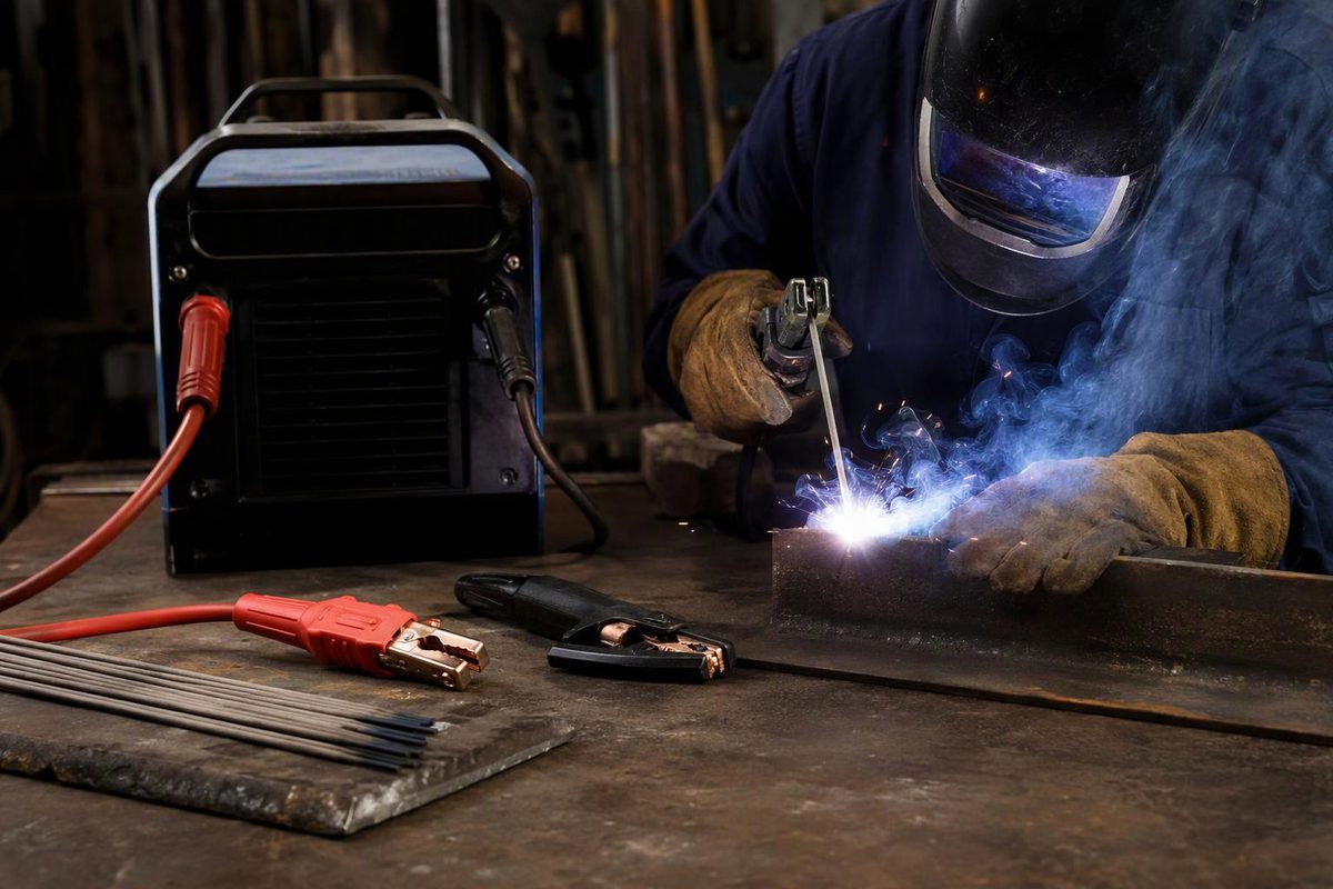
DCEP—electrode positive—is a common choice for stick welding, but the correct polarity comes from the electrode’s instructions and the welding procedure. For DCEP, the electrode holder connects to positive (+) and the work lead connects to negative (−). DCEN reverses those connections. AC alternates polarity and requires an AC-compatible electrode.
Do not choose polarity from metal thickness alone. The electrode covering affects which current types work and how the rod behaves; some electrodes allow several options, while others have a narrower operating range. Lincoln Electric’s polarity guidance explains why the container recommendation matters.
What DCEP, DCEN and AC mean
The letters refer to the electrode, not the work clamp.
| Current/polarity | Electrode holder connection | Work lead connection | Other name |
|---|---|---|---|
| DCEP | Positive (+) | Negative (−) | DC+, reverse polarity |
| DCEN | Negative (−) | Positive (+) | DC−, straight polarity |
| AC | Follow the machine’s AC connection instructions | Follow the machine’s AC connection instructions | Alternating current |
DC maintains a fixed polarity. AC reverses direction repeatedly, so it has no permanently positive or negative electrode connection. Lincoln Electric calls “electrode positive” and “electrode negative” more descriptive terms than “straight” and “reverse.”
On machines with marked +/− output terminals, changing DC polarity generally means swapping the two welding leads. Other machines use a selector or electronic control: follow the manual rather than assuming every connector works the same way.
Before moving leads, turn the welder off and disconnect input power as directed by its manual. Ensure connectors are secure and cables are sound. These are explicit connection precautions in the Miller Multimatic 220 manual, section 5-8.
Which polarity does each stick rod use?
Use this as a product-specific reference, not a substitute for the box in your hand. The following examples are Lincoln Electric electrodes:
| Classification and product | Published current/polarity options | Setup implication |
|---|---|---|
| E6010, Fleetweld 5P+ | DCEP preferred; DCEN ranges also listed for 3/32, 1/8 and 5/32 inch | Start with DCEP unless the instructions and procedure call for an alternative. No AC range is listed. |
| E6011, Fleetweld 35 | AC preferred; DCEP and DCEN listed | Do not assume every E6011 product has identical DC guidance. |
| E6013, Fleetweld 37 | AC preferred; DCEP and DCEN listed | Several options are available, but use the appropriate current range. |
| E7018, Excalibur 7018 MR | DCEP preferred; AC listed | DCEN is not a listed option for this product. |
Here, “preferred” follows the manufacturer’s note that the first-listed polarity is preferred. Where its chart says DC±, that means either DC electrode positive or DC electrode negative—not AC.
When changing between permitted current types, check the amperage range again: it may differ. For example, Excalibur 7018 MR lists different lower limits for DCEP and AC at 1/8-inch diameter. For diameter-specific comparisons, see the stick welding setting chart.
What polarity changes in the weld
For many covered stick electrodes, DCEP generally produces deeper penetration, while DCEN produces faster electrode melt-off and a higher deposition rate. The covering chemistry can change that behavior. Lincoln explicitly identifies those exceptions in its polarity explanation.
That is why “put the hotter side on the work” is not a dependable selection rule. Stick welding uses a consumable, flux-covered electrode; its behavior cannot be reduced to terminal signs alone.
DCEN may help on thinner material when the electrode and procedure permit it, but reversing an electrode specified for DCEP is not a reliable burn-through fix. Check rod diameter, amperage, travel and fit-up first. Miller’s stick technique guide treats polarity as an electrode-dependent choice alongside current, arc length and travel speed.
AC can also be useful when magnetic arc blow deflects a DC arc, provided both the machine and electrode support AC stick welding. ESAB’s stick polarity guide identifies this application.
Diagnose an unstable arc before swapping polarity
Wrong polarity can cause an erratic arc, excessive spatter, poor penetration or abnormal electrode burn-off—but those symptoms do not prove polarity is the fault. Lincoln’s guidance lists these effects.
Check in this order:
- Identify the exact electrode and diameter. Read its current options and operating range; check the welding procedure where one applies.
- Verify the actual setup. Trace the holder and work cables to their terminals, or check the polarity selector. Confirm stick mode and the required output type.
- Check the work circuit. Clean the clamp contact area and inspect connections. Miller stresses that a solid electrical connection is important to arc quality; the work-circuit guide covers checks beyond the clamp itself.
- Check current and technique. Low amperage can cause sticking or arc extinction; an excessively long arc can cause spatter, undercut and porosity. Correct these before experimenting with another permitted polarity. Miller’s troubleshooting guidance explains the distinction.
- Test on representative scrap. Keep material, joint, position and rod size comparable; change one variable at a time. A steadier arc or smoother bead does not establish internal fusion or certify the weld. Production work must meet its procedure and inspection requirements.