
Flux Core MIG Welding Tips for a More Stable Arc
Check wire-specific polarity, tip distance and feeding before adjusting settings. Practical flux-core technique and a symptom-first troubleshooting sequence.
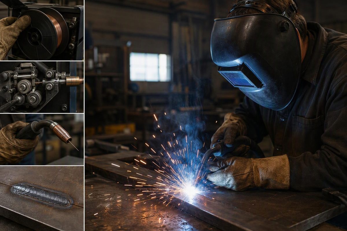
For a more stable flux-core arc, check wire identity, polarity, feeding and contact-tip distance before changing voltage. Then work on gun angle and travel speed. Adjusting settings around a mechanical fault usually makes troubleshooting harder.
“Flux core MIG” commonly means self-shielded flux-cored arc welding, or FCAW-S. It uses tubular wire whose flux provides shielding without a gas cylinder. Gas-shielded FCAW requires external gas; the two setups are not interchangeable. These tips focus on self-shielded mild-steel welding. Miller explains the distinction.
1. Read the spool before connecting the leads
Check the wire’s exact product name, classification and diameter against its datasheet and your machine manual. Verify:
- Required polarity and whether external gas is needed.
- Permitted welding positions and single- or multipass use.
- Compatible drive rolls, liner and contact tip.
- Operating range and any material-thickness limits.
Do not assume every flux-cored wire uses the same polarity. For example, Hobart Fabshield 21B, an E71T-11 self-shielded wire, specifies DC electrode negative (DCEN): the gun connects to negative and the work lead to positive. That is a product-specific instruction, not a rule for every tubular wire. Fabshield 21B datasheet
If you are converting from solid-wire MIG, use the gasless flux-core setup checklist before striking an arc.
2. Clean the joint and establish reliable feeding
Flux-core wire tolerates some contamination better than solid-wire MIG, but that does not make rust, scale, oil or paint good welding surfaces. Clean the joint thoroughly and expose clean metal where the work clamp attaches. Poor clamp contact adds resistance to the welding circuit. Miller’s preparation guidance
With power isolated as the manual directs, inspect the feed path. Use the manufacturer-specified roll type and groove size; knurled rolls are commonly recommended for soft tubular wire. Set roll pressure and spool-hub tension by the manual—not by tightening both until the wire moves. Excess pressure can deform the wire, while incorrect tension can produce erratic feeding. Replace worn tips or liners and reject rusty wire. Miller’s equipment checks
3. Hold the specified tip-to-work distance
Stickout and contact-tip-to-work distance are different measurements. Stickout is the unmelted wire extending beyond the contact tip, excluding the arc. Contact-tip-to-work distance, or CTWD, runs from the tip to the workpiece and includes the arc gap.
Use the measurement named in the wire’s chart. A general “flux-core stickout” recommendation should not override product data. For example, Hobart specifies 1/2 inch (13 mm) CTWD for .035-inch Fabshield 21B, but 3/4 inch (19 mm) for its 1/16-inch diameter. Hobart’s operating table
Keep that distance consistent through the test bead. Do not measure from the nozzle unless the manual explicitly tells you to: a recessed contact tip changes the relationship.
4. Drag with a modest angle; avoid unnecessary weaving
For basic self-shielded mild-steel welds, use a drag technique: point the wire back toward the completed weld while moving away from it. Miller recommends a 5–15-degree travel angle for normal conditions. Excessive tilt can increase spatter, reduce penetration and destabilize the arc.
Work angle is separate from travel angle. For practice in the flat position, start approximately perpendicular to an equal-thickness butt joint, or bisect an equal-thickness, 90-degree T-joint at about 45 degrees. Different thicknesses, joint arrangements and welding positions may need different aim. Miller’s gun-angle guidance
Start practice with a straight stringer bead rather than a broad weave. Watch the molten metal wet into both joint faces—not just the slag covering it. Keep travel steady so the puddle does not run ahead of the arc and trap slag. If the wire and procedure permit multiple passes, clean all slag from each pass before depositing another. Bernard and Tregaskiss on slag inclusions
5. Tune on representative scrap, not on the repair
Use scrap matching the actual steel thickness, joint, gap and welding position. Begin with the machine chart for the correct process and wire, checked against the consumable’s operating range.
As an example—not a thickness recommendation—Hobart lists 19 V, 110 inches/minute wire feed and approximately 80 A for .035-inch Fabshield 21B at 1/2-inch CTWD. Those values describe one operating point; they do not establish that a particular joint has enough fusion. Fabshield 21B operating data
Make a short bead, remove the slag and inspect it. Change one variable at a time and record the result. Treat charts as starting points, not proof of a sound weld.
6. Troubleshoot the symptom in order
These are first checks, not definitive diagnoses. The defect guidance comes from Miller and Bernard and Tregaskiss; wire-specific limits still govern adjustments.
| Symptom | Check first | Then consider |
|---|---|---|
| Excessive spatter | Polarity, steady tip distance, clean and correctly sized contact tip | Voltage/feed mismatch; low voltage can cause heavy flux-core spatter |
| Wire burns back into the tip | Interrupted feeding, gun held too close | Feed speed too low for the operating point |
| Porosity or pinholes | Oil, moisture, coatings, excessive wire extension | Shielding conditions and whether the wire actually requires gas |
| High, rope-like bead with poor toe tie-in | Gun aim and whether the arc reaches both joint faces | Parameters too cold; compare voltage/feed with the wire chart |
| Burn-through | Excessive gap, thin edges and accumulated heat | Lower voltage/feed or increase travel speed within the usable range |
| Slag trapped between passes | Incomplete cleaning and inaccessible bead edges | Bead placement, travel speed, angle and insufficient heat input |
Protect yourself—and verify more than appearance
Use an appropriate welding helmet, safety glasses, leather gloves, flame-resistant clothing and suitable footwear; clear fire hazards before welding. Miller’s PPE guidance
Self-shielded does not mean fume-free. Understand the hazards of the base metal, coatings and consumable. Keep your head out of the plume and use suitable ventilation or local exhaust. OSHA specifically warns that outdoor welding does not guarantee adequate ventilation; respiratory protection may be required if work practices and ventilation do not reduce exposure to safe levels. OSHA welding-fume guidance
A tidy bead can still contain lack of fusion or buried slag. For structural, lifting, pressure or other safety-critical work, use the applicable welding procedure and required qualification and inspection—not appearance or a successful practice bead as acceptance.