
Before You MIG-Repair a Casting, Decide Whether It Should Be Welded
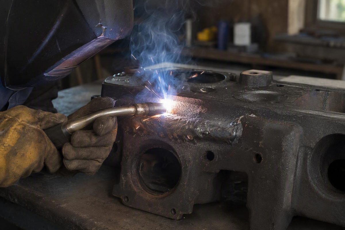
Can You MIG Weld Cast Iron? The Qualified Answer
Yes, cast iron can sometimes be MIG welded. The important qualification is that depositing a bead is not the same as producing a reliable repair.
A possible MIG candidate is generally a known, noncritical gray-iron casting with accessible damage, manageable restraint, thorough decontamination, a compatible consumable, a documented heat-control method, and a defined inspection plan. These factors are only screening considerations; they do not establish that a particular component is weldable or fit for service.
It should not automatically be transferred to ductile, malleable, white, or unidentified iron. Cast-iron grades differ in graphite form, mechanical behavior, and response to welding, and they can be difficult to distinguish without reliable records or metallurgical analysis.
Process recommendations also vary. Some commercial MIG guides accept nickel-bearing or explicitly cast-iron-rated wire for selected repairs. Broader conventional guidance more often recommends nickel-electrode shielded metal arc welding, or SMAW. R-Tech, for example, says MIG may work in some circumstances but names MMA/SMAW as its preferred process for gray-iron repair; it does not provide controlled comparative data proving that every MIG repair is weaker (R-Tech’s cast-iron welding guidance).
The available sources likewise do not establish that MIG and nickel SMAW produce equivalent strength, fatigue life, machinability, or leak resistance. Results depend on the iron, filler, joint design, dilution, contamination, thermal cycle, restraint, workmanship, and inspection.
This article is therefore limited to go-or-no-go assessment and high-level crack-risk reduction for noncritical repairs. It is not a welding procedure specification, engineering approval, code-compliant repair instruction, or substitute for the selected consumable manufacturer’s current documentation.
Before choosing MIG, evaluate:
- The cast-iron type and condition
- The component’s function and consequences of failure
- Static, impact, vibration, and fatigue loading
- Whether the part retains pressure or fluid
- Casting geometry and restraint
- Oil, paint, and other contamination
- Required post-repair machining
- Applicable manufacturer or code restrictions
- Required inspection and acceptance criteria
- Whether replacement or a lower-risk repair is practical
The first question is not “What setting should I use?” It is “Should this component be fusion welded at all?”
Start With a Go-or-No-Go Repair Decision
Begin with the component’s function, not the welding machine available.
A low-stress cover, decorative bracket, nonpressurized guard, or lightly loaded housing presents a different decision from a lifting attachment, steering or braking part, structural connection, rotating component, or pressure-retaining casting. As a conservative screening policy, an improvised MIG repair should not proceed when failure could injure someone, release pressure or fragments, compromise a structure, or disable critical equipment. A DIY cast-iron case study similarly warns against applying its method to structural or safety-critical components (the MIG-Welding.co.uk cast-iron repair account).
Treat the following as reasons for professional engineering evaluation, specialist repair, or replacement rather than an improvised MIG repair:
- Lifting or overhead-load components
- Braking, steering, or suspension parts
- Structural or primary load-bearing members
- Rotating parts whose failure could release fragments
- Pressure vessels, hydraulic bodies, or pressurized housings
- Highly loaded or fatigue-sensitive machinery
- Components governed by a repair code or manufacturer restriction
- Parts that cannot be inspected against defined acceptance criteria
Next, identify the material as far as reasonably possible. Gray, ductile, malleable, and white cast iron do not have identical weldability. Manufacturer records, casting documentation, service information, controlled testing, or metallurgical analysis may help. A visual guess or spark test alone may not settle the question.
The commonly published methods center on gray iron. White iron is commonly described as effectively or virtually unweldable by conventional repair methods because of its brittleness, although that does not prove that no specialist foundry process could ever address it. Ductile and malleable iron also need procedures suited to their metallurgy rather than an assumed gray-iron recipe. Red-D-Arc distinguishes the four broad types and emphasizes that filler, preparation, preheat, and process depend on the casting involved (Red-D-Arc’s cast-iron overview).
Stop and reassess if any of these conditions remain unresolved:
- The iron type is unknown
- The crack ends cannot be located
- Damage extends behind an inaccessible boss, flange, or cavity
- Large areas are missing or fragmented
- The casting is severely oil-saturated
- Critical alignment cannot be maintained or measured
- Distortion could compromise machined bores or sealing faces
- The part is highly restrained
- The completed repair cannot be examined adequately
- Previous repairs have produced recurring cracks or hard zones
Also determine whether the repaired area must be drilled, bored, milled, tapped, or otherwise machined. Filler selection affects deposit hardness and machinability. Lincoln Electric’s gray-iron guidance differentiates nickel stick electrodes partly according to whether machining is required and whether the repair involves one or multiple passes (Lincoln Electric’s gray-iron repair guidance).
Compare the available repair routes before committing to MIG:
- Nickel SMAW: Often the better-documented fusion-welding choice for gray iron.
- Brazing or MIG brazing: May reduce base-metal melting and contraction stress in suitable noncritical joints, but should not be assumed to equal a fusion weld in strength.
- Mechanical stitching: Avoids fusion-welding heat and may be preferable where distortion or cracking is unacceptable.
- Studding or mechanical reinforcement: Can transfer part of the load mechanically instead of relying entirely on a brittle fusion zone.
- Specialist foundry repair: Appropriate for valuable, complex, contaminated, or metallurgically uncertain castings.
- Replacement: Often the most defensible option when failure consequences or repair uncertainty are high.
Passing this initial screen does not approve the repair. It only establishes whether obtaining a qualified procedure, exact consumable documentation, and appropriate inspection requirements is worth pursuing.
Why Cast Iron Cracks When It Is Welded
Cast iron commonly contains approximately 2% to 4% carbon, while most steels contain less than 2%. That higher carbon content and cast iron’s lower ductility are central to its welding difficulty (Red-D-Arc’s explanation of cast iron versus steel).
Three related mechanisms matter.
Fusion heat changes the local metallurgy. The arc melts filler and some base metal. Carbon from the casting can enter the weld region, contributing to hard, brittle structures in the weld or heat-affected zone. The resulting area may tolerate less strain precisely where thermal and geometric stresses are concentrated.
The weld contracts during cooling. Weld metal shrinks as it solidifies and returns toward room temperature. Ductile steel can accommodate some strain through deformation. Brittle cast iron has less ability to yield before cracking. Large weld volumes, long beads, deep excavations, and rigid fit-up can increase contraction forces.
Localized heating creates thermal gradients. The arc rapidly heats a small area while the surrounding casting remains cooler. The hot zone tries to expand against the rest of the part and then contracts while that mass restrains it. Thick-to-thin transitions, corners, bosses, holes, and old repairs complicate the stress pattern.
Cracking can occur through the deposit or beside it. It may happen during welding, produce audible ticking during cooling, or become visible only after the part is fully cold.
A DIY lathe-repair account illustrates the risk. The author deposited a neat-looking seam with ordinary mild-steel MIG wire and no preheat. The casting made “tinkling” sounds while cooling, and the pieces separated after the weld cooled. The author attributed the failure to contraction and a hard, brittle region caused by carbon entering the steel-rich deposit (the reported lathe gearbox experiment).
That account is anecdotal, not a controlled process comparison. Its useful lesson is narrower: bead appearance is not proof of repair quality. A smooth cap cannot verify internal soundness, strength, fatigue life, machinability, or leak tightness.
Choose the Process and Filler Before Choosing Settings
Ordinary mild-steel MIG wire is a risky default for cast iron. Fusion can introduce carbon into the steel-rich weld region, promoting a hard and crack-sensitive microstructure, while cooling contraction loads the less-ductile casting. Successful steel welding with a particular spool does not make that wire suitable for cast iron.
One retailer guide discusses specialized flux-cored wire, while another published case used solid nickel-iron-manganese wire. That variation is a reason to require exact product documentation, not a reason to combine the gas, polarity, or operating range from unrelated examples (Welding Supplies from IOC’s MIG cast-iron guidance).
Before proceeding, obtain the current manufacturer datasheet for the exact wire and verify:
- Compatible cast-iron grades
- Whether the wire is solid or cored
- Approved base-metal combinations
- Required shielding gas
- Polarity
- Available wire diameters
- Preheat requirements
- Interpass temperature limits
- Operating range
- Position limitations
- Deposit hardness and machinability
- Post-weld cooling or heat-treatment requirements
If this documentation is unavailable, the evidence does not support inventing a MIG setup.
Nickel SMAW deserves serious consideration because conventional gray-iron guidance documents its electrode-selection path more clearly, including choices influenced by machining requirements and pass count. That does not prove that every stick repair is stronger than every MIG repair. It means the published selection framework is more established.
Brazing can be useful where limiting base-metal fusion matters more than reproducing a fusion joint. Mechanical stitching or stud reinforcement may reduce dependence on weld-metal strength and avoid imposing a severe fusion-welding cycle across the entire defect.
| Process | Typical reason to consider it | Heat and cracking concerns | Machinability considerations | Conditions requiring specialist input |
|---|---|---|---|---|
| MIG with verified cast-iron-rated wire | Selected noncritical repair supported by exact consumable documentation | Fusion, dilution, thermal gradients, and contraction can crack the casting | Depends on the wire, dilution, and resulting heat-affected zone | Unknown iron, high restraint, pressure, fatigue loading, or incomplete documentation |
| Nickel SMAW | Conventional gray-iron repair with established electrode options | Still requires disciplined heat management and cooling | Nickel-rich electrodes may be selected where machining matters | Coded, loaded, pressure-retaining, or metallurgically uncertain work |
| Brazing or MIG brazing | Reduce base-metal fusion in a suitable joint | Lower base-metal melting does not eliminate thermal stress | Deposit and heated area may machine differently from the casting | High loads, elevated temperatures, pressure, or uncertain joint strength |
| Mechanical stitching | Avoid fusion heat and limit distortion | Requires sound surrounding material and engineered placement | May preserve nearby machined geometry | Complex load paths, thin walls, or cracks near sealing faces |
| Stud-assisted repair | Add a mechanical load path across a break | Local welding or brazing may still initiate cracks | Studs can interfere with later machining | Loaded parts, critical alignment, or inadequate material around holes |
| Replacement or specialist repair | Reduce uncertainty where failure consequences are high | Avoids an improvised field-welding cycle | New fitting or machining may still be required | Safety-critical, pressure, structural, rare, or valuable components |
Do not choose voltage, amperage, wire-feed speed, gas mixture, gas flow, travel speed, or transfer mode from a generic online recipe. Those variables interact with wire construction and diameter, polarity, machine characteristics, section thickness, groove geometry, position, preheat, and repair design. The starting parameters must come from the exact consumable manufacturer and, where consequences warrant it, a qualified repair procedure.
Prepare the Casting to Sound, Clean Metal
Preparation principles are broadly supported, but they do not form a complete MIG procedure.
Disassemble the component where practical. Remove bearings, seals, lubricants, wiring, trapped fluids, and heat-sensitive parts before welding or broad heating. Disassembly can also improve access for cleaning, alignment checks, and examination of the reverse side.
Strip the repair area to clean metal. Remove:
- Paint and coatings
- Rust and scale
- Grease and surface oil
- Casting skin
- Loose graphite
- Failed weld metal
- Fractured or crushed edges
- Sealants and previous repair compounds
Cleaning the visible surface may not be enough. Engine, gearbox, axle, pump, and differential castings may retain oil in pores or cracks. Trapped combustible liquids can also create a fire hazard.
Do not invent a bake-out temperature. Deeply embedded contamination requires a manufacturer-approved or professionally specified decontamination method that accounts for the casting, contaminant, ventilation, fire control, distortion, and possible metallurgical effects.
Welding over the visible line can leave the root or branched cracking untouched. Depending on access and wall thickness, excavation and examination may be necessary from more than one side.
V- and U-grooves are commonly discussed for exposing sound material and providing access. Their actual angle, depth, root geometry, and land must come from the joint design and qualified procedure. Rounded U-groove edges may reduce sharp local heat concentration. One DIY source favors chipping rather than grinding in some situations to avoid smearing graphite, but that is a shop observation rather than a universal prohibition on grinding.
Clean again after excavation. Abrasive debris, graphite, cutting fluid, and newly released oil can contaminate an otherwise sound groove.
Restore alignment without adding unnecessary rigid restraint. On precision housings, record the dimensions of bearing bores, shaft centers, gasket faces, bosses, and mounting planes before repair so any movement can be evaluated afterward.
Pre-weld decision checklist
- [ ] The casting type is identified with reasonable confidence
- [ ] The component’s function and failure consequences are documented
- [ ] The complete defect is accessible
- [ ] Paint, oil, rust, graphite, and damaged material can be removed
- [ ] Embedded contamination has been addressed by an approved method
- [ ] The joint or insert design reaches sound material
- [ ] Critical dimensions and alignment references are recorded
- [ ] Fit-up does not impose unnecessary restraint
- [ ] The exact consumable datasheet is available
- [ ] Gas, polarity, temperature limits, and operating range come from that datasheet
- [ ] A compatible heat-control method is defined
- [ ] Suitable temperature-measurement equipment is available
- [ ] The cooling arrangement is specified
- [ ] Inspection method and acceptance criteria are defined before welding
- [ ] PPE, ventilation, electrical safety, and hot-work controls are in place
Welding exposes operators and nearby personnel to electrical current, radiation, hot metal, fumes, grinding debris, shielding gases, and fire hazards. Use suitable PPE and ventilation and follow the welding machine manual, consumable instructions, workplace controls, and applicable site rules (ARCCAPTAIN’s general cast-iron welding safety guidance).
Choose One Heat-Control Strategy and Follow It Consistently
Gray-iron repair literature describes two distinct heat-management philosophies:
- Uniformly heat the casting, maintain controlled heat during welding, and cool it slowly.
- Keep the casting relatively cool while applying very short, separated deposits with substantial pauses.
This establishes that different repair philosophies exist. It does not establish temperatures, bead lengths, or interpass limits for a particular MIG wire.
Do not casually blend the approaches. Heating one part of a casting substantially, leaving another area cold, and then switching to an improvised cool-repair method can create uncontrolled thermal gradients. The selected MIG consumable documentation or qualified procedure must determine which strategy applies.
Uniform-preheat approach
The principle is to reduce the temperature difference between the weld area and the rest of the casting. Heating should be slow and even rather than concentrated at the groove. The documented preheat and interpass condition must then be maintained while localized arc energy is controlled, followed by the specified cooling cycle.
Lincoln Electric’s SMAW-focused gray-iron guidance gives a broad preheat range of 500–1,200°F, warns against exceeding 1,400°F, discusses approximately one-inch weld segments, and describes slow cooling under an insulating blanket or in dry sand. These figures demonstrate one manufacturer’s gray-iron stick-repair method; they are not universal MIG parameters and should not be transferred to MIG unless the selected wire manufacturer or qualified procedure confirms them (Lincoln Electric’s hot and cool gray-iron methods).
Other commercial sources publish different general temperature ranges. The disagreement reinforces why the correct temperature depends on the casting grade, filler, geometry, mass, restraint, and procedure.
Use temperature crayons, contact probes, thermocouples, or another instrument appropriate to the specified range and surface. Do not use bare-hand contact as a temperature-control method.
Relatively cool short-deposit approach
The alternative philosophy limits the size of each heated zone and allows cooling between separated deposits. Locations and deposit ends may be distributed to avoid concentrating heat and contraction in one line. Craters require proper termination because abrupt ends can become crack-sensitive locations.
Lincoln’s statement that gray iron should remain cool enough to touch belongs to its stick-electrode guidance. It is descriptive, not a complete MIG procedure and not an instruction to measure temperature by touching the casting. For MIG, measured limits must come from the selected wire documentation or qualified procedure.
Where an approved procedure permits MIG repair, it may instead specify controlled stringer deposits, distributed placement, or backstepping. Those details must be procedure-specific rather than improvised.
Cooling and peening
Cooling is part of the repair plan. An insulating blanket or dry sand appears in gray-iron guidance as a way to slow heat loss during a hot procedure. Any insulation must be dry, noncombustible, compatible with the component, and approved for the selected method.
Do not improvise rapid cooling with water or compressed air. Commercial cast-iron guidance warns that accelerated cooling can increase fracture risk (R-Tech’s preparation and cooling guidance).
Peening is conditional, not automatically beneficial. It may also be restricted by the governing procedure or code. Use it only when expressly permitted and defined; retailer guidance itself notes both possible stress relief and procedural restrictions on peening.
A Cautious MIG Repair Workflow Without Universal Machine Settings
Because the evidence pack lacks a first-party MIG-wire datasheet and a validated procedure connecting iron grade, wire, gas, polarity, temperatures, joint design, and operating parameters, the following is a document-control workflow, not a welding sequence.
-
Define the service risk. Document the component’s function, loading, pressure exposure, restraint, and consequences of failure. Stop if those consequences exceed the scope of a noncritical repair.
-
Confirm the material. Obtain reliable identification of the casting. If the grade remains unknown, do not assume it is gray iron.
-
Select the repair process. Compare nickel SMAW, MIG with a verified consumable, brazing, mechanical stitching, specialist repair, and replacement. Process availability is not evidence of suitability.
-
Obtain controlling documentation. Secure the exact MIG-wire manufacturer’s current instructions and any component-manufacturer, engineering, or code requirements. The documentation must establish compatible iron grades, gas, polarity, temperature limits, operating range, and cooling requirements.
-
Develop the joint and restraint plan. Specify defect removal, groove or insert geometry, fit-up, alignment control, and critical dimensions. Do not derive these from a generic online example.
-
Develop the contamination-control plan. Address surface contamination, embedded oil, trapped fluids, and previous repair material before welding.
-
Select one documented heat strategy. Confirm whether the applicable procedure uses uniform preheat or a relatively cool, interrupted-deposit method. Do not borrow temperature or bead-length instructions from an unrelated SMAW procedure.
-
Define monitoring and stop criteria. Specify temperature measurement, contamination indicators, distortion limits, and what conditions require the repair to stop.
-
Define cooling before welding begins. Prepare the approved insulation or natural-cooling arrangement. Protect the casting from unplanned rapid or uneven cooling.
-
Define inspection and acceptance. The component manufacturer, governing code, repair engineer, or qualified inspection professional must select the method, timing, technique, and acceptance criteria. A DIY visual check cannot qualify a consequential component.
A mild-steel coupon does not reproduce cast iron’s carbon content, graphite structure, restraint, contamination, or cooling behavior, and no scrap test validates a safety-critical repair.
Case-specific settings—not a general recipe
In a hobbyist repair of a punctured 1964-vintage Chevrolet P-case differential carrier, the author used a Hobart Handler 210, 0.035-inch Royal 44-30 nickel-iron-manganese wire, and 75% argon/25% carbon dioxide. After practicing on 3/16-inch steel, he reported voltage setting 5, wire-speed setting 45, and gas flow of 30 cfh. He fitted a 3/16-inch mild-steel plug, preheated the casting, lightly peened the joint, and cooled it gradually (the complete Hemmings case study).
Those numbers describe only the reported machine, consumable, gas, joint, and casting. They are not recommendations. The steel practice coupon could not reproduce the casting’s metallurgy, contamination, restraint, or cooling response.
Troubleshoot the Repair and Inspect It After Full Cooling
Do not bury a developing defect under more weld. A symptom is a reason to stop and reassess the material, documentation, joint, and heat strategy—not simply to add another pass.
| Symptom | Conditions to investigate | Decision response |
|---|---|---|
| Cracking during welding | Incorrect material identification, excessive restraint, incompatible filler, concentrated heat, incomplete crack removal, or a procedure mismatch | Stop; do not continue until the repair concept has been reviewed |
| Ticking during cooling | Active contraction cracking, steep thermal gradients, or rapid heat loss | Do not quench or disturb the planned cooling cycle; treat the repair as suspect |
| Cracks visible after cooling | Residual stress, brittle heat-affected regions, crater defects, or hidden crack branches | Do not return the component to service; obtain qualified evaluation |
| Porosity | Embedded oil, paint, moisture, sealant, graphite, or shielding problems | Stop and address the source; do not cap over porous metal |
| Dirty or erratic deposit | Contamination, poor electrical return, incorrect gas or polarity, or unsuitable wire | Verify the surface, welding circuit, and exact consumable instructions |
| Apparent lack of fusion | Poor access, contamination, incorrect arc placement, or settings outside the documented range | Do not raise heat indiscriminately; reassess the joint and procedure |
| Distortion or lost alignment | Excessive deposited metal, concentrated heating, poor sequence, or excessive restraint | Stop and measure critical features before proceeding |
| Leakage | Through-cracks, adjacent cracking, porosity, or incomplete joint formation | Do not assume another surface pass will provide a reliable seal |
Recurring contamination can indicate oil retained deep in the casting. Recurring cracks can indicate unsuitable iron, filler, restraint, geometry, or repair concept. Stitching, brazing, specialist repair, or replacement may then be more rational.
Examine the casting only after its documented cooling cycle is complete. At minimum, look for visible discontinuities at:
- The weld surface and toes
- The adjacent heat-affected area
- Original crack ends
- Starts, stops, and craters
- Nearby bosses, ribs, corners, and bolt holes
- Machined mounting or gasket faces
- Bearing bores and aligned features
- The reverse side, where accessible
Visual examination is not proof of fitness for service. Additional methods—potentially including surface testing, dimensional measurement, leak testing, hardness evaluation, or professional nondestructive examination—must not be improvised from this article. Their suitability, timing, test conditions, and acceptance criteria must come from the component manufacturer, governing code, repair engineer, or qualified inspection procedure.
Likewise, no universal waiting period for delayed inspection is supported here. If delayed cracking is a concern, the responsible authority must specify when reinspection occurs and what findings are acceptable. The absence of a visible crack does not establish strength, fatigue life, leak tightness, or long-term serviceability.
What Two DIY Case Studies Demonstrate—and What They Do Not
Case studies can expose practical problems, but they cannot establish a universal repair procedure.
The first involved a punctured 1964-vintage Chevrolet cast-iron differential carrier. The hobbyist author fitted a 3/16-inch mild-steel plug and joined it with 0.035-inch Royal 44-30 nickel-iron-manganese wire, a Hobart Handler 210, and 75% argon/25% carbon dioxide. Reported preparation included extensive degreasing, filing and beveling the opening, preheating, keeping the casting warm, light peening, and gradual cooling (Hemmings’ differential-carrier case study).
The useful design lesson is that a fitted insert can reduce the volume of weld metal needed to close a large opening.
The limitations are substantial. The report provided no destructive testing, pressure testing, metallurgical examination, quantified hardness results, or documented long-term service validation. The author identified himself as a hobbyist and acknowledged that more controlled heating and cooling would have been more conventional. The outcome illustrates one repair; it does not establish general reliability for automotive castings.
The second example involved a broken gearbox casting on a 1950s Kerry Model C lathe. The author drilled and tapped one section, installed mild-steel studs, cut mating slots, and applied short MIG-brazed sections. Welding only one side of each stud allowed some movement as the deposit contracted. The gearbox was reported functional after one year, but its service was described as comparatively light and no measured strength validation was supplied.
That repair’s useful lesson is the reduction of fusion-weld dependence through mechanical reinforcement. It does not establish suitability for vehicles, structures, lifting equipment, pressure systems, or safety-critical machinery.
The same author’s failed mild-steel-wire experiment provides the contrast: the seam looked neat while hot but cracked apart during cooling.
Case studies can illustrate ideas. They cannot replace:
- A defensible go-or-no-go decision
- Reliable identification of the casting
- The exact filler manufacturer’s current instructions
- A coherent and documented heat-control strategy
- Engineering judgment for consequential service
- Inspection requirements with defined acceptance criteria
Frequently Asked Questions
Can you MIG weld cast iron with regular mild-steel wire?
A MIG machine can deposit mild-steel wire onto cast iron, but that does not make it a dependable repair method. Carbon can enter the steel-rich weld region and contribute to a hard, brittle microstructure, while cooling contraction loads the comparatively brittle casting. Cracking may occur through the deposit or beside it.
Do not justify mild-steel wire because the bead wets in or looks clean while hot. Use only a consumable whose current manufacturer documentation explicitly supports the identified cast iron and intended procedure. If that documentation is unavailable, reconsider the process.
What MIG wire should be used for cast iron?
Use a nickel-bearing or other MIG consumable explicitly approved by its manufacturer for the identified cast-iron grade and repair conditions. Do not select wire by alloy nickname alone.
Verify:
- Compatible cast-iron grades
- Solid or cored construction
- Shielding gas and polarity
- Wire diameter and feed requirements
- Preheat and interpass limits
- Operating range
- Deposit hardness and machinability
- Cooling or post-weld requirements
Published examples include both specialized flux-cored products and nickel-iron-manganese solid wire. Consequently, there is no evidence-supported universal wire-and-gas combination.
Does cast iron always need to be preheated before welding?
Not necessarily. Gray-iron repair guidance describes both a uniform-preheat method and a relatively cool method using short, separated deposits.
Those approaches are not interchangeable, and SMAW temperatures or bead lengths should not be transferred to MIG without confirmation. The applicable method and temperature limits must come from the exact MIG consumable documentation or a qualified repair procedure.
Is MIG or stick welding better for cast-iron repair?
Nickel-electrode stick welding is more commonly recommended and more fully documented in the available conventional gray-iron guidance. It offers established electrode choices based partly on machining and pass requirements.
MIG may still be considered for a narrow class of noncritical repairs when the casting is identified and the wire manufacturer explicitly supports the application. The available evidence does not prove that every MIG repair is weaker than every SMAW repair, nor does it establish equivalence.
Choose according to the material, service demand, restraint, machining requirements, governing documentation, and consequences of failure—not process preference.
How do you check a cast-iron repair for cracks after welding?
Allow the casting to complete its documented cooling cycle before judging it. Then visually examine the weld, toes, adjacent heated region, original crack ends, craters, nearby geometric features, and reverse side where accessible.
Any additional inspection method, timing, test conditions, and acceptance criteria must be selected by the component manufacturer, governing code, repair engineer, or qualified inspection professional. An intact-looking bead does not by itself prove strength, fatigue life, machinability, or leak tightness.
The practical hierarchy is simple: first decide whether the component should be welded at all. If it remains a defensible noncritical candidate, identify the iron, select a verified filler, and obtain a documented procedure using one consistent heat strategy. Then prioritize decontamination, low-restraint preparation, minimized weld volume, controlled cooling, and inspection against defined acceptance criteria.
MIG can be useful for a narrow class of cast-iron repairs. Uncertainty about the alloy, consumable, procedure, loading, inspection, or consequences of failure is a reason to choose nickel SMAW, brazing, mechanical repair, specialist evaluation, or replacement—not a reason to guess at settings.