
Choose the Right TIG Filler by Metal, Joint, and Service
ER308L in an inconvenient diameter may still be the correct alloy; ER70S-6 in a convenient diameter is still unsuitable for 304 stainless.
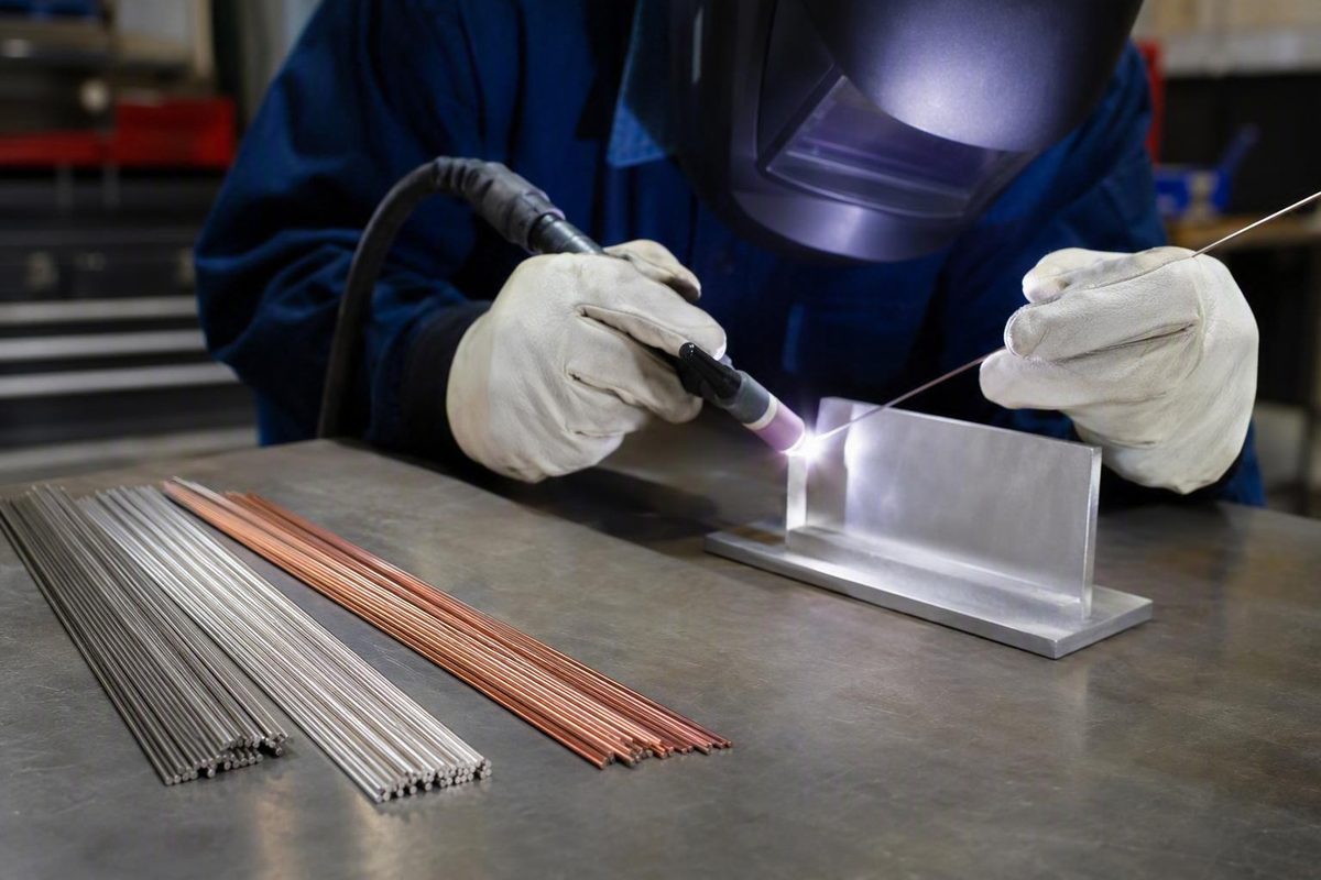
Choosing rods for TIG welding requires two separate decisions. First, select a filler-metal classification compatible with the exact base alloy, required weld properties, service environment, heat treatment, and controlling procedure. Then choose a physical rod diameter that suits the puddle heat, joint geometry, fit-up, position, and required deposit volume.
Those decisions are related but not interchangeable. ER308L in an inconvenient diameter may still be the correct alloy; ER70S-6 in a convenient diameter is still unsuitable for 304 stainless. Common classifications and stocked sizes are useful starting points, but no filler or diameter is universal.
Technical scope: The alloy associations below summarize commercial guides and practitioner material rather than replacing current AWS specifications, filler-manufacturer compatibility charts, engineering review, or a qualified welding procedure specification (WPS). Compatibility-sensitive and code-governed work requires those controlling documents.
What TIG filler rod is—and when a joint needs it
TIG filler rod is bare filler metal manually fed into the molten weld puddle during gas tungsten arc welding, or GTAW. It is separate from the tungsten electrode held in the torch. The tungsten establishes and sustains the arc; the filler adds metal to the joint.
Retailers may describe the consumable as:
- TIG rod
- TIG filler rod
- Filler wire
- TIG welding wire
- GTAW filler metal
These terms may identify the same general consumable, but product form matters. Cut-length rod is supplied as straight lengths for manual feeding. Spooled wire arrives in coils for equipment fitted with an appropriate wire-feeding system. Check the product form instead of assuming that everything called “wire” is packaged as hand-fed rod.
A flux-coated SMAW stick electrode is not interchangeable with bare TIG filler. Its coating, intended process, handling, and operating characteristics differ. TIG guidance calls for clean, bare, uncoated filler identified for GTAW—not an intact or stripped stick electrode of uncertain suitability (Weld Guru’s TIG filler guide).
Not every TIG joint requires filler. Autogenous welding—fusing the prepared base-metal edges without adding filler—can be appropriate for selected, closely fitted joints when the design and approved procedure permit it.
Filler is commonly needed when:
- A root opening or other gap must be bridged
- A groove or bevel requires deposited weld metal
- A fillet must reach a specified size
- The joint requires reinforcement or added cross-sectional area
- The specified weld-metal chemistry differs from simple fusion of the base materials
- Fit-up does not permit controlled autogenous welding
The joint design, material, required properties, and applicable procedure determine whether filler-free welding is acceptable. If filler is required, select its chemistry first and its diameter second.
A base-metal-first process for selecting TIG filler
A label such as “steel,” “stainless,” or “aluminum” is not enough to select filler reliably. Similar-looking metals can differ in chemistry, heat treatment, corrosion behavior, strength, and weldability.
Use this sequence before purchasing:
- Identify the exact base-metal grade. Check material markings, drawings, purchase records, certificates, or reliable alloy-identification results.
- Determine whether the joint is similar or dissimilar. Record both grades when joining different materials.
- Define the required weld properties. Consider strength, ductility, toughness, corrosion resistance, operating temperature, fatigue exposure, and any specified appearance requirements.
- Account for thermal history. Record the supplied temper or condition and any planned postweld heat treatment.
- Review the service environment. Chemical exposure, seawater, elevated temperature, cyclic loading, and pressure service may change the acceptable filler.
- Review the joint. Note thickness, groove, bevel, gap, root opening, position, access, and required deposit volume.
- Check controlling documents. Consult the approved WPS, engineering specification, applicable code, and filler- or base-metal-manufacturer compatibility data.
- Select the filler classification.
- Select the diameter and package format.
Matching filler broadly to the base-metal family is only a starting rule. Dissimilar joints may require a deliberately different weld-metal composition. Heat-treated materials may need filler and thermal procedures selected around final properties rather than simple chemistry matching. Corrosive and elevated-temperature service can also rule out an otherwise familiar pairing.
The following matrix is for orientation only. Every entry is a candidate to verify—not an automatic prescription.
| Base metal or joint | Candidate filler family to verify | Primary checks |
|---|---|---|
| Carbon or mild steel | ER70S-2, ER70S-3, or ER70S-6 | Exact steel grade, preparation, strength, toughness, joint type, and WPS |
| 304 or 304L stainless | ER308L | Confirmed grade, corrosion medium, temperature, dilution, and procedure |
| 316 or 316L stainless | ER316L | Confirmed grade, required corrosion performance, environment, and WPS |
| Stainless to carbon steel | ER309L | Both grades, dilution, temperature, corrosion exposure, and engineering approval |
| Selected 6XXX aluminum, including some 6061 and 6063 work | ER4043 or ER5356 | Exact alloy, temper, strength, ductility, finish, temperature, and compatibility chart |
| Many 5XXX aluminum applications | ER5356; other 5XXX fillers in selected cases | Exact magnesium-bearing alloy, temperature, corrosion exposure, and required properties |
| 4130 tubing | ER70S-2 or, for selected requirements, ER80S-D2 | Tubing specification, heat treatment, strength and ductility requirements, and WPS |
| Titanium | Grade-matched ERTi filler | Exact grade, shielding, cleanliness, preparation, and qualified procedure |
| Copper-nickel | ERCuNi | Exact copper-nickel alloy, service environment, and engineering requirements |
Commercial guides commonly list the carbon-steel, stainless, aluminum, and copper-nickel starting families shown above, while 4130 and titanium guidance is especially dependent on material condition and the complete welding procedure (Welding & Welder’s classification guide; Weld Guru’s 4130 and titanium guidance).
If the alloy is unknown, resolving its identity is part of filler selection—not an optional step after buying the rod.
For structural, pressure, marine, aerospace, safety-related, or code-governed work, follow the approved WPS and engineering requirements.
How to read AWS-style filler classifications
ER70S-6 is a useful example of an AWS-style carbon-steel filler designation:
- ER means the product can be used as an electrode or rod.
- 70 denotes a 70,000 psi deposited-weld tensile-strength class.
- S identifies solid filler.
- -6 is a chemistry-related suffix that distinguishes it from other fillers in the family.
That structure helps identify the product, but it should not be applied indiscriminately to every designation. Stainless, aluminum, nickel, copper, titanium, and specialty classifications do not necessarily encode information in the same way as ER70S-6.
Commercial guides associate these filler families with the following specifications:
- AWS A5.18: carbon-steel filler metals
- AWS A5.9: stainless-steel filler metals
- AWS A5.10: aluminum and aluminum-alloy filler metals
- AWS A5.14: nickel and nickel-alloy filler metals
- AWS A5.7/A5.7M: copper and copper-alloy filler metals
The ER70S-6 code and these specification families are summarized in commercial classification guidance, but the full classification still must be checked against the exact material, application, and controlling specification (YesWelder’s classification overview).
The “70” does not prove that ER70S-6 is suitable for every steel requiring that nominal tensile-strength class. It does not establish base-metal compatibility, impact toughness, heat-treatment response, corrosion resistance, service-temperature suitability, or approval under a WPS.
Before buying, verify:
- Complete classification, including every suffix
- Alloy or material family
- Rod diameter
- Cut length, spool, or other product form
- Package weight
- Manufacturer identity
- Lot identification required by the job
- Certificate of conformance, test report, or other required documentation
For controlled work, verify the applicable edition, classification, and documentation directly through the governing documents and manufacturer.
TIG rods for mild steel and low-alloy steel
ER70S-2, ER70S-3, and ER70S-6 are familiar carbon-steel TIG fillers, but their shared ER70 designation does not make them identical or freely interchangeable.
| Classification | Reported chemistry or deoxidizer emphasis | Common application descriptions | Reported behavior | Important caveats |
|---|---|---|---|---|
| ER70S-2 | Often described as triple-deoxidized, with aluminum, titanium, and zirconium in addition to silicon and manganese | Pipe or tube, root passes, precision work, and selected critical applications | Commonly chosen where controlled handling and root work matter | Not restricted to perfectly clean steel; suitability still depends on material and procedure |
| ER70S-3 | Commonly associated with clean carbon steel | General clean-steel fabrication | Less thoroughly differentiated in the available guidance | Do not assume unrestricted substitution for S-2 or S-6 |
| ER70S-6 | Relatively high silicon and manganese | General fabrication and steel with light mill scale or less-than-ideal surface condition | Often described as comparatively fluid | Deoxidizers do not make preparation unnecessary or guarantee sound welds through contamination |
Supplier guidance describes ER70S-2 as triple-deoxidized and commonly associated with pipe, roots, and precision or critical work; ER70S-3 with clean steel; and ER70S-6 with higher silicon and manganese for less-clean carbon steel (Welding & Welder’s carbon-steel comparison).
That evidence does not justify a simple “S-2 for clean metal, S-6 for dirty metal” rule. In one practitioner comparison, ER70S-2 and ER70S-6 behaved similarly on clean carbon steel and light mill scale. ER70S-6 was described as more fluid and was preferred by that practitioner for certain open-root or full-penetration joints (Jody Collier’s ER70S-2 versus ER70S-6 comparison).
The practical conclusion is narrower: ER70S-6 may offer useful deoxidizer chemistry and puddle behavior when surfaces are not pristine, but it is not permission to weld through rust, oil, paint, heavy scale, or unknown contamination. Prepare the joint as required by the process and WPS.
ER70S-2 and ER70S-6 both belong to a nominal 70,000 psi deposited-weld tensile-strength class, but they differ in chemistry and may differ in handling and approved application (Southern Arc’s ER70S-2 and ER70S-6 comparison). A shared strength class does not authorize substitution under a WPS.
ER80S-D2 is a low-alloy, higher-strength candidate for selected applications—not a universal upgrade. A higher nominal strength may be undesirable where the design instead requires a particular balance of ductility, toughness, fatigue performance, and base-metal compatibility.
For 4130 tubing, ER70S-2 is commonly suggested for many applications, while ER80S-D2 is sometimes considered when a different strength response is required. Heat-treated 4130 intended to achieve optimum properties may instead require chemistry-matching filler and a procedure designed around the complete thermal cycle. The tubing specification, engineering requirements, and WPS should control the decision.
ER309 or ER309L may be considered for selected carbon-to-stainless joints. It is a specialty dissimilar-metal candidate, not a general mild-steel repair rod and not a cure for contaminated or unidentified material.
Stainless steel rods: ER308L, ER316L, and ER309L
Stainless filler selection begins with the exact base grade and service conditions. “Stainless” covers multiple alloy systems, and corrosion performance depends on more than whether the finished bead remains bright.
| Candidate filler | Common starting pairing | Primary verification points |
|---|---|---|
| ER308L | 304 or 304L stainless | Exact base grade, corrosion medium, temperature, dilution, and WPS |
| ER316L | 316 or 316L stainless | Exact grade, required corrosion performance, environment, and procedure |
| ER309L | Many stainless-to-carbon-steel joints | Both materials, dilution, temperature, corrosion exposure, and engineering approval |
These pairings are candidates rather than prescriptions. ER308L should not be selected merely because a component looks like 304. ER316L is not automatically safer simply because it contains a different alloy balance. ER309L does not apply to every dissimilar combination.
Commercial guidance also associates ER347 with 321/347 stainless and elevated-temperature service, ER2209 with duplex stainless, and ER2594 with super-duplex stainless (specialty stainless associations in Welding & Welder’s guide). These associations are not complete application instructions. Duplex and elevated-temperature systems require alloy-specific manufacturer data and procedure control.
That does not make it a universal rod for unknown steels, cast iron, tool steel, contaminated repairs, or every joint described as “dissimilar.” Base-metal identity, cracking history, restraint, temperature, and service remain material considerations.
Keep physical diameter separate from alloy selection. Thin stainless sheet is often welded with comparatively modest puddle heat, so a smaller filler may be easier to add without excessively chilling the puddle. That is a practical guideline, not a fixed rule. Joint type, gap, position, travel speed, and deposit requirements still determine the appropriate diameter.
Aluminum and specialty fillers
ER4043 and ER5356 are common aluminum fillers, but neither is universally best.
| Filler | Alloy system | Commonly discussed uses and behavior | Selection limits |
|---|---|---|---|
| ER4043 | Aluminum-silicon | Selected 6XXX applications, including some 6061 and 6063 work; often described as smooth-flowing and less crack-sensitive | Verify exact alloy, strength, ductility, finish, temperature, heat treatment, and manufacturer data |
| ER5356 | Aluminum-magnesium | Many 5XXX and some 6XXX applications, including selected marine work | Not appropriate for every 5XXX or 6XXX alloy; alloy- and service-specific restrictions must be checked |
The difference extends beyond puddle feel. Required strength, ductility, postweld finishing, color response, corrosion exposure, operating temperature, and heat treatment may favor one filler or rule one out. Manufacturer compatibility charts and the controlling procedure should decide the issue, especially for production and critical work.
Do not extend a general ER4043-versus-ER5356 comparison to unidentified castings, unknown alloys, or unspecified 2XXX, 7XXX, and heat-treated aluminum. The available evidence does not establish a dependable universal compatibility matrix for those materials.
Commercial guidance also lists ER5183 and ER5556 for selected higher-strength 5XXX applications and ER2319 for alloy 2219 (aluminum filler associations in Welding & Welder’s guide). These examples illustrate why “aluminum rod” is too broad a buying category; use documentation for the exact alloy and condition.
Titanium guidance generally calls for close matching between filler grade and base-metal grade. Common examples include ERTi-2 for grade 2 and ERTi-5 for grade 5. Critical titanium welding also requires procedure-specific control of cleanliness, shielding, preparation, and handling. Buying a nominally matching rod is only one part of the process.
ERCuSi-A silicon bronze belongs in a different conceptual category. Commercial guidance cites thin sheet, galvanized components, automotive panels, and HVAC work as possible contexts. Brazing is appropriate only where the design and procedure permit it; it must not replace a specified fusion weld merely to reduce distortion.
ERCuNi is a candidate for selected copper-nickel alloys and applications involving marine piping, heat exchangers, condensers, or seawater service. Exact alloy matching and engineering requirements remain controlling.
Commercial catalogs also carry nickel, bronze, hardfacing, low-alloy steel, stainless, and other specialty families (Airgas’s GTAW filler catalog). Catalog breadth demonstrates availability—not compatibility, technical superiority, or approval for a particular weld.
How to choose TIG filler-rod diameter
There is no single best TIG filler diameter and no dependable one-size-per-material-thickness rule.
Diameter should reflect:
- Base-metal thickness
- Available puddle heat
- Actual welding current
- Joint type
- Root opening or gap
- Bevel and groove volume
- Welding position
- Fit-up consistency
- Travel speed
- Required bead or fillet size
- Amount of deposited metal needed per addition
- The welder’s ability to feed consistently
A smaller rod melts quickly and allows fine additions. It can work well with thin material and small puddles, but it may require rapid or nearly continuous feeding when a joint needs substantial fill.
A larger rod contributes more metal per dip. It may suit larger fillets, grooves, or gaps, but only if the puddle can melt it promptly. If the rod is oversized for the available heat, it may chill the puddle, melt slowly, and make the torch dwell in one area. That added dwell can overheat or burn through the base metal rather than cooling the joint beneficially.
The commonly stocked cut-length diameters of 1/16, 3/32, and 1/8 inch are practical starting options, not mandatory matches to particular material thicknesses (Harris’s TIG rod catalog).
For example, 1/16-inch filler can be a reasonable starting point on some 1/8-inch steel joints. That does not make it universally correct. A tight butt joint, open root, wide gap, groove, and fillet on the same plate thickness can require different deposition rates.
Practitioners also disagree about when 3/32-inch filler becomes preferable. One may use it successfully to add more metal or influence puddle behavior, while another may find it difficult to melt at the available current. An informal discussion of 1/8-inch steel illustrates that disagreement, but the contributors’ qualifications are unknown and the thread should be treated only as anecdotal evidence (WeldingWeb’s discussion of filler size on 1/8-inch steel).
One setup-specific demonstration compared 1/8- and 1/16-inch filler on 16-gauge steel at a machine setting of 55 amps. The 1/8-inch rod took longer to melt, increasing dwell and contributing to an attempted burn-through; the 1/16-inch rod melted faster and allowed quicker travel. This was an informal practitioner demonstration, not a controlled test or universal crossover rule (Kevin Caron’s filler-diameter demonstration).
Do not infer a universal amperage threshold from one welder’s habits. Likewise, attractive bead appearance does not establish penetration, soundness, mechanical properties, or code compliance.
Diameter troubleshooting
- Rod melts slowly or repeatedly sticks at the puddle edge: The diameter may be too large for the available puddle heat. Check current, arc length, torch position, and joint conditions before changing size.
- The torch must dwell while waiting for the rod: Consider smaller filler or greater appropriate puddle heat, subject to the procedure and base-metal limits.
- Excessive bead buildup: Too much metal may be added per dip, the filler may be too large, travel may be too slow, or the joint may not require that deposit volume.
- Small filler disappears too quickly: Increase feed rate or consider a larger diameter if the puddle can melt it and the joint requires more fill.
- Aluminum filler balls before reaching the puddle: Shorten the arc and reduce excessive torch angle before assuming diameter is the problem. Introduce the filler at the leading edge while keeping it within the shielding envelope (practitioner guidance on TIG filler size).
- Burn-through occurs while using a large rod at low current: Slow melting may be increasing local dwell. A smaller rod can sometimes reduce the time spent waiting for filler to flow.
- The bead is flat, undercut, or overheated-looking: Review current, arc length, travel speed, filler timing, gap, and deposit volume together. Diameter alone may not be the cause.
The best diameter is the one that can be fed and melted predictably while producing the required deposit under the approved parameters. It is not necessarily the smallest, largest, or most commonly stocked option.
A practical TIG rod buying checklist
Before purchasing rods for TIG welding, verify the following in order.
-
Exact classification Confirm the complete designation, including every suffix. ER70S-2 and ER70S-6 are not the same product; neither are ER308L and ER309L.
-
Compatibility documentation Check the filler manufacturer’s product data, the base-metal manufacturer’s compatibility information where applicable, and the controlling WPS or engineering specification. A retailer’s “commonly used for” description is not sufficient for procedure-sensitive work.
-
Diameter Select for the actual joint, current range, position, fit-up, and deposit volume. If the work varies, purchasing more than one diameter may be justified.
-
Cut length or spool format Confirm whether the product is straight cut-length rod or spooled wire. Manual TIG normally calls for a form suited to hand feeding unless the equipment includes an appropriate wire feeder.
-
Package weight Small packs can suit one-off repairs, trials, and rarely used alloys. Larger packages may be more practical for repetitive shop work if the material can remain identified and properly handled.
-
Manufacturer identity Confirm that the filler and its documentation can be traced to the stated manufacturer rather than relying on an incomplete marketplace description.
-
Packaging condition As a general purchasing and identity-control practice, look for intact packaging and filler protected from obvious dirt, moisture, damage, and mixing. Material-specific storage, cleaning, or conditioning requirements must come from the manufacturer and the applicable quality procedure.
-
Required traceability or certification Verify any lot identity, certificate of conformance, test report, or other documentation required by the contract, code, customer, or quality system. Do not assume every package includes those records.
Commercial catalogs commonly show 36-inch cut-length rods, including 1/16-, 3/32-, and 1/8-inch diameters, although other sizes are available. They also show 1-pound packs for small jobs or testing, 10-pound packs for higher consumption, and bulk or spooled formats for production (Arc-Zone’s packaging overview).
Sealed tubes and boxes are packaging approaches marketed to limit dirt, moisture, and contamination. They do not prove indefinite shelf life or replace manufacturer handling instructions. Do not create one shop-wide drying or storage schedule for every filler family without material-specific documentation.
Preserve classification identity after opening a package. Keep different alloys and diameters segregated, retain their labels, and do not return uncertain rods to a marked container. This is a general identity-control practice, not a substitute for formal handling requirements.
Compare prices only after normalizing:
- Classification
- Diameter
- Package weight
- Product form
- Manufacturer
- Required documentation
- Shipping and handling
A lower package price may simply represent less filler, a different diameter, another product form, or the absence of required documentation. Changing prices and stock labels are not durable technical criteria.
Stop before buying if the alloy is unknown, the service is critical, or the WPS names a filler. Identify the base material and follow the controlling documentation instead of purchasing the closest familiar classification.
Welding involves hazardous current, fumes, ultraviolet radiation, heat, and hot material. Use appropriate PPE, ventilation, equipment instructions, and site controls. Equipment manuals and site rules take precedence over general articles (Welder Facts’ welding safety notice).
Frequently Asked Questions
What TIG rod should I use for mild steel?
ER70S-2, ER70S-3, and ER70S-6 are common candidates. ER70S-2 is often associated with tubing, roots, and precision work; ER70S-3 with clean carbon steel; and ER70S-6 with relatively high silicon and manganese and less-than-pristine surfaces.
Clean and prepare the steel regardless of classification. Choose from the exact base grade, joint, required properties, and WPS rather than treating ER70S-6 as a universal dirty-steel rod. Selected low-alloy applications may call for ER80S-D2 or another specified filler.
What TIG filler is commonly used for 304 stainless steel?
ER308L is a common starting candidate for 304 and 304L stainless. Verify that the base metal is actually 304 or 304L, then check corrosion exposure, operating temperature, dilution, joint design, and the approved procedure.
A familiar pairing does not authorize substitution on critical or code-governed work.
Should I use ER4043 or ER5356 for 6061 aluminum?
Both may be candidates for selected 6061 applications, but they are not universally interchangeable. ER4043 is an aluminum-silicon filler commonly associated with smooth flow and lower crack sensitivity. ER5356 is an aluminum-magnesium filler considered where its property profile better suits the application.
The decision depends on required strength and ductility, service temperature, corrosion exposure, finishing or color requirements, heat treatment, and manufacturer compatibility data. Use the controlling procedure rather than choosing solely by availability.
What size TIG filler rod should I use on 1/8-inch steel?
A 1/16-inch rod can be a reasonable starting point for some 1/8-inch steel joints. A 3/32-inch rod may suit a larger fillet, gap, groove, or higher-deposition requirement if the puddle can melt it promptly.
There is no automatic thickness-to-diameter match. Joint type, root opening, fit-up, current, position, travel speed, and feed technique may change the choice. If the rod melts slowly and forces excessive dwell, it may be too large for the available puddle heat.
Can a stick-welding electrode be used as TIG filler rod?
A flux-coated SMAW stick electrode should not be treated as interchangeable with bare TIG filler. Use clean, bare filler identified for GTAW and carrying the classification required for the job.
Removing flux from an unknown or unsuitable stick electrode does not establish the chemistry, cleanliness, documentation, or procedure compatibility needed for TIG welding.
The repeatable decision rule is straightforward: identify the exact alloy, determine the required weld and service properties, verify the candidate classification against manufacturer data and the controlling procedure, and only then choose a diameter suited to the puddle heat and joint volume. ER70S-2, ER308L, ER4043, and ER5356 are useful starting points—not universal answers. If the alloy is unknown or the weld is critical, resolve the material and procedure requirements before purchasing or welding.