
Choose the Right TIG Shielding Gas and Flow
Learn which argon to buy for TIG welding, choose a practical CFH starting range, estimate cylinder runtime, and diagnose shielding failures safely.
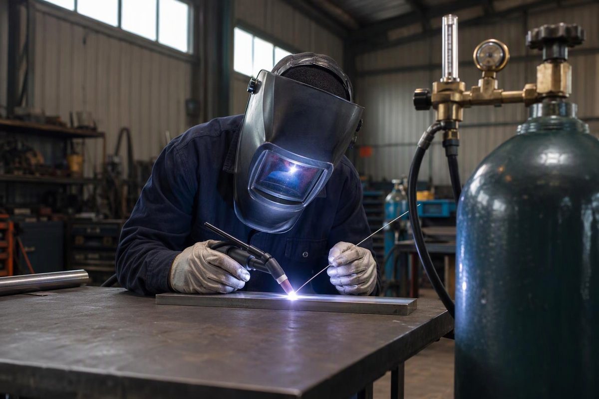
For most TIG welding, 100% argon sold for welding is the practical default. It works with carbon steel, stainless steel, aluminum, nickel alloys, and many other metals while providing reliable arc starts and a stable arc. Start with the torch manufacturer’s flow range, then use the lowest flow that completely shields the tungsten, filler tip, and weld pool.
Select your torch setup and cylinder capacity to see the CK flow range and ideal gas-on time.
Argon Flow and Runtime Calculator
Ranges below apply to the listed CK Worldwide ferrous-metal setups. A torch manual or WPS takes priority.
The shorter runtime uses the higher flow. Actual useful time is lower because this ideal estimate excludes preflow, postflow, purging, leakage, and residual pressure.
| Listed Setup | Standard | Gas Lens |
|---|---|---|
| 1/16 in, #4–#6 | 7–12 CFH | 5–10 CFH |
| 3/32 in, #6–#8 | 10–15 CFH | 8–10 CFH |
| 1/8 in, #7–#10 | 10–18 CFH | 8–12 CFH |
Source: CK Worldwide TIG Technical Guide argon ranges for ferrous metals. Runtime uses cylinder capacity ÷ flow and is an ideal estimate.
Helium and engineered argon blends have legitimate uses, but they are application choices—not fixes for a leaking torch, dirty joint, or incorrect setup. If a WPS, equipment manual, or project specification names a gas, that requirement overrides a general recommendation.
Argon Provides Stable TIG Shielding
In gas tungsten arc welding (GTAW), shielding gas keeps the surrounding atmosphere away from the electrode and molten metal. Losing that shield can oxidize the tungsten and weld pool or contribute to porosity. Gas composition also changes arc starting, stability, and heat transfer, so it is part of the welding procedure rather than merely a consumable supply.
Argon is the usual default because it starts and stabilizes the arc more readily than helium. Helium transfers more heat and can help on thick or highly conductive material, but it generally requires more flow and makes high-frequency arc starting less consistent.
Argon-helium blends split the difference. Miller describes common blends containing 25% to 75% helium and notes that heat increases while starting performance and stability decrease as helium content rises (Miller Electric). For an aluminum-specific comparison, see whether aluminum TIG needs helium.
Do not substitute a MIG bottle merely because its label includes argon. A 75% argon/25% CO₂ cylinder is an active-gas blend intended for wire processes, not a general TIG gas. One supplier’s lineup, for example, assigns its 99.998% argon product to GTAW while assigning its argon/CO₂ mixtures to GMAW, FCAW, or MCAW (Airgas). Carbon dioxide or oxygen in the shielding gas can oxidize the tungsten and change weld chemistry.
Special gases do exist. Pure helium and argon-helium blends may be specified where additional heat is useful, while argon-hydrogen blends can be used for selected austenitic stainless applications (Air Products). Do not improvise a hydrogen-bearing blend. The base metal, procedure, joint service, and safety requirements must all permit it.
Ask the Supplier for Welding-Grade Argon
Ask for 100% argon intended for welding in a cylinder whose valve matches the regulator or flowmeter approved for your equipment and jurisdiction.
“Pure argon” does not mean absolute chemical purity. One current welding product is specified as 99.998% Ar (Airgas). That is an example product specification, not proof that every TIG job requires that exact grade. Reactive alloys and controlled work may impose tighter impurity limits, so use the gas specification stated by the procedure.
Cylinder ownership, exchange policies, valve connections, and available sizes vary by supplier. Before buying a cylinder online or secondhand, confirm that a local supplier will fill or exchange it and will accept its ownership markings and test status.
A cylinder’s nominal gas capacity provides a rough runtime estimate. Ideal gas-on time equals cylinder capacity in cubic feet divided by flow in cubic feet per hour.
A 125-ft³ cylinder at 15 CFH works out to about 8.3 hours of gas-on time. Actual useful time is lower because of preflow, postflow, purging, leakage, residual pressure, and changing conditions. This estimates gas-on time, not elapsed shop time.
Start Within the Torch’s Published Flow Range
There is no single correct CFH setting. Cup diameter, standard collet body versus gas lens, tungsten extension, joint geometry, torch angle, and drafts all change the coverage needed.
For common manual work with small and medium cups, 10–20 CFH (about 5–9.5 L/min) is a useful trial range, not a universal setting. Published Miller guidance spans 10–35 CFH overall, depending on consumables and surrounding conditions (Miller Electric).
CK Worldwide’s more specific chart gives these argon examples for ferrous metals:
| Listed Torch Setup | Standard Body | Gas Lens |
|---|---|---|
| 1/16-in tungsten, #4–#6 cup | 7–12 CFH | 5–10 CFH |
| 3/32-in tungsten, #6–#8 cup | 10–15 CFH | 8–10 CFH |
| 1/8-in tungsten, #7–#10 cup | 10–18 CFH | 8–12 CFH |
These are starting ranges from the manufacturer’s TIG technical guide, not a replacement for the torch manual or WPS. Aluminum ranges in the same chart can be higher, especially as cup and electrode size increase.
Set and read the flow while gas is moving, then test on representative clean material. Use the lowest flow that maintains complete shielding. Too little flow leaves the pool exposed; too much can make the gas stream turbulent and draw room air into it.
Lincoln’s Aspect 300 manual gives a broad argon range of 7–16 L/min for commonly used torches and specifically warns that excessive flow can aspirate atmospheric contamination (Lincoln Electric). Turning the flowmeter higher can therefore make contamination worse.
A gas lens straightens the gas stream and usually supports better coverage or greater tungsten extension than a standard collet body. It does not make the torch windproof. Block drafts rather than trying to overpower them with more CFH, and position fume extraction so it captures contaminants without stripping away the shielding envelope.
Set Up the Entire Gas Path
- Secure the cylinder upright. Keep it away from heat and impact, and install the protective cap for transport or storage.
- Verify every component. The cylinder valve, regulator or flowmeter, hose, and power-source connection must be compatible with argon service and rated for the pressure involved.
- Connect clean, undamaged fittings. Follow the gas supplier’s and regulator manufacturer’s instructions. Do not use improvised adapters.
- Check for leaks. Inspect the cylinder connection, hose, machine fittings, torch head, collet body or gas lens, cup, and insulators. A sound flowmeter reading does not prove that all the metered gas reaches the cup.
- Set preflow and postflow. Preflow clears air from the torch before ignition. Postflow protects the cooling tungsten and weld end. Hold the torch in place until postflow ends. Miller recommends at least 0.2 second of preflow and gives amperage divided by 10 as a postflow rule, with an eight-second minimum; use the machine manual or procedure value where one is specified (Miller Electric).
- Clean the work and filler separately. Argon cannot correct oil, oxide, moisture, mill scale, or contaminated filler. Gas choice also does not replace correct filler selection; match the rod to the base metals and service requirements using the principles in choosing TIG welding rods.
Stainless pipe and other full-penetration joints may also need argon on the root side because torch shielding protects only the face. Miller identifies backside oxygen exposure as the cause of stainless “sugaring” and names argon back purging as the primary preventive method (Miller Electric). Purge flow, venting, oxygen limits, and dam arrangement should come from the governing procedure.
Diagnose the Gas Path Before Increasing Flow
When the tungsten discolors, the bead oxidizes, or porosity appears, change one variable at a time.
- Read the cylinder label. Confirm 100% argon or the exact specified blend—not an argon/CO₂ MIG mix.
- Confirm actual flow at the cup. Check that the valve is open, the hose is not pinched, and the flowmeter responds with gas moving.
- Look for leaks or assembly faults. Inspect O-rings, back cap, torch body, hose, machine solenoid connections, gas lens or collet body, cup, and insulator.
- Remove drafts. Check fans, open doors, and the position of extraction equipment.
- Correct torch geometry. Excessive arc length, torch angle, or tungsten stickout can move the pool beyond the shielding envelope.
- Check timing. Allow enough preflow, then keep the cup over the crater and tungsten through postflow.
- Restore cleanliness. Regrind contaminated tungsten and clean the joint and filler with methods suitable for the alloy.
- Adjust flow last. Move in small increments within the torch or procedure range. If increasing CFH makes the result worse, suspect turbulence or a leak that admits air into the gas path.
Argon coverage can prevent atmospheric contamination, but it cannot establish penetration, fusion, or code acceptance. A clean-looking TIG bead still has to meet the joint design, approved procedure, and required inspection or testing.
Argon Requires Ventilation and Secure Handling
Treat argon as both a compressed gas and a simple asphyxiant. The current Airgas SDS warns that it can displace oxygen and cause rapid suffocation, requires adequate ventilation, and calls for cylinders to be upright and secured (Airgas SDS).
Do not enter a confined space where a release may have created an oxygen-deficient atmosphere unless the applicable confined-space controls have been met.