
When a TIG Gas Lens Helps—and How to Set It Up
Learn what a TIG gas lens changes, match it to your torch and tungsten, choose cup size and gas flow, and troubleshoot poor shielding.
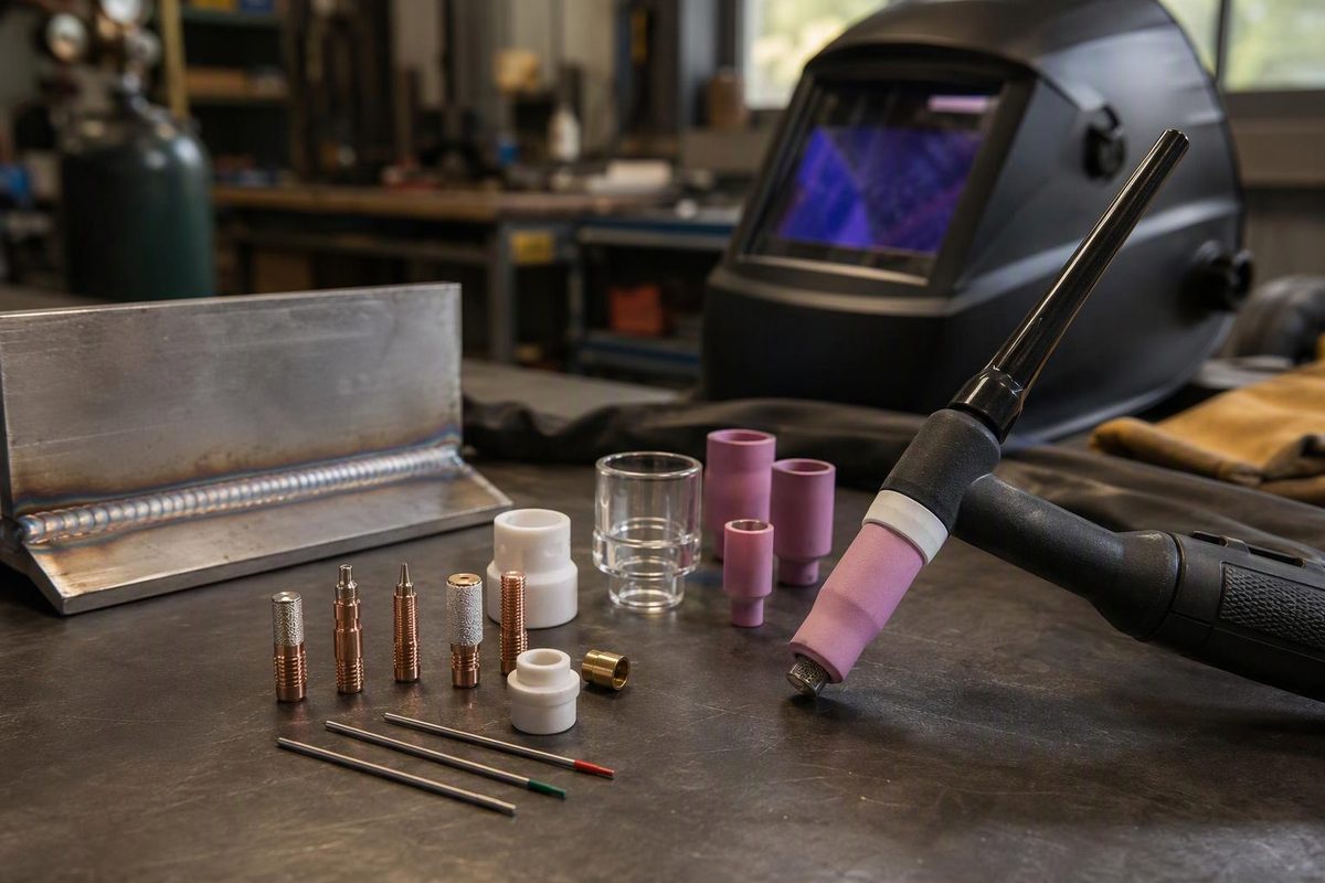
A TIG welding gas lens replaces the standard collet body with a screened gas-distribution assembly. Its main benefit is smoother shielding-gas flow, which can improve coverage and allow more tungsten extension for access into a narrow joint. It is useful when shielding or torch access is the limitation—not a cure for dirty material, leaks or incorrect welding settings. ESAB’s TIG shielding guidance explains both the coverage benefit and the longer-stickout advantage.
What the gas lens changes
The collet grips the tungsten; the collet body supports that assembly and distributes gas toward the cup. A gas-lens body adds layered mesh screens that smooth and straighten the flow before it leaves the nozzle. The “lens” is not an optical component, and a clear cup is not what makes an assembly a gas lens. Arc-Zone describes the screened construction.
The practical advantage is a more consistent gas envelope around the tungsten and weld pool. That matters when you need to see past the cup or reach into a groove without losing shielding. However, the gas still has to reach the hot metal: excessive extension, drafts and poor torch positioning can defeat the improvement.
Tungsten stickout and arc length are different. Stickout is the distance from the cup face to the tungsten tip; arc length is the gap from the tip to the work. A lens may let you increase stickout while keeping a short arc. Extending the tungsten does not justify holding the arc farther from the joint. CK’s torch troubleshooting manual identifies both excessive stickout and a long arc as problems to correct.
Choose a matched assembly, not just a lens
Order by the torch model and consumable configuration, not the welding-machine brand. CK’s compatibility listings illustrate the common families:
| Torch family | CK consumable family |
|---|---|
| CK9 / CK20 | 2 Series, commonly identified as 13N |
| CK17 / CK18 / CK26 | 3 Series, commonly identified as 10N |
| CK17 / CK18 / CK26 with a stubby conversion | 4 Series stubby |
These are CK’s listings, not a guarantee that every aftermarket part interchanges. Confirm your torch’s parts diagram, especially for specialty heads and conversion kits. CK consumable compatibility
Before buying, check:
- Tungsten diameter: the collet and gas-lens body must suit the electrode size.
- Cup fit: use a cup specified for that lens or conversion system; the same cup number does not establish thread compatibility.
- Insulator or heat shield: include the part specified for the assembly.
- Conversion type: standard, stubby and large-diameter systems are distinct configurations.
A matched kit can reduce guesswork, but check its contents. For example, CK’s Gas Saver kits use a collet body and separate tungsten-adapter screen, plus a heat shield, collet and cup. Do not assume those parts are identical to a conventional gas-lens assembly. CK kit contents
For a broader parts checklist, see TIG welding consumables and compatibility.
Cup size, stickout and gas flow
Common numbered TIG cups express the opening diameter in sixteenths of an inch: a #6 is 3/8 inch, about 9.5 mm; a #8 is 1/2 inch, about 12.7 mm. The number describes the opening—not the tungsten diameter or fitting system. CK’s cup listings
Choose an opening that covers the pool while still allowing access. A larger cup is not automatically better if it forces an awkward torch angle. Start with only the tungsten extension needed to reach the joint; increase it cautiously on scrap representing the actual joint. There is no universal maximum stickout that remains shielded with every lens, cup and flow rate.
CK gives 15–20 CFH, approximately 7–9.4 L/min, as a typical TIG flow range. Treat that as a starting reference, not a gas-lens-specific prescription: cup size, gas composition, joint geometry and the welding procedure can require something different. Excessive flow can create turbulence and draw surrounding air into the shielding zone. CK flow guidance
Set flow with gas actually flowing, using the equipment’s gas-test or purge function where available. When delivery is suspect, use a compatible nozzle flow tester to check what reaches the torch rather than relying only on the cylinder-side reading. Keep welding output disabled during the test and follow the tester’s instructions. CK explains nozzle flow testing. For gas selection and runtime, see argon gas for TIG welding.
If shielding gets worse after fitting a lens
Work through the setup before turning up the regulator:
- Check assembly and condition. With power off and the torch cool, confirm the specified cup, lens, collet and insulator. Inspect for cracks, obstructed screens and damaged seals.
- Check gas delivery. Look for hose restrictions and leaking connections; verify flow at the nozzle with welding output disabled.
- Reduce exposure. Shorten unnecessary stickout, maintain a short arc and shield the work from cross-drafts without disabling required ventilation.
- Check contamination and timing. Clean the base metal and filler, reprepare contaminated tungsten, and verify preflow and postflow against the equipment instructions or welding procedure specification (WPS).
CK’s troubleshooting manual lists leaks, blockages, drafts, excessive extension and contamination as separate causes. A lens addresses gas distribution; it does not eliminate the others.
It also does not replace backside purging where the material and procedure require it. ESAB discusses backside protection separately. Evaluate the change on representative test pieces, and use the applicable inspection requirements—not bead color or appearance alone—to judge weld acceptance.