
Choose Aluminum Filler by Alloy, Joint, and Service Conditions
ER4043 and ER5356 differ in fluidity, crack risk and anodized color when both are permitted. Guidance warns against ER5356 above about 150°F in sustained service.
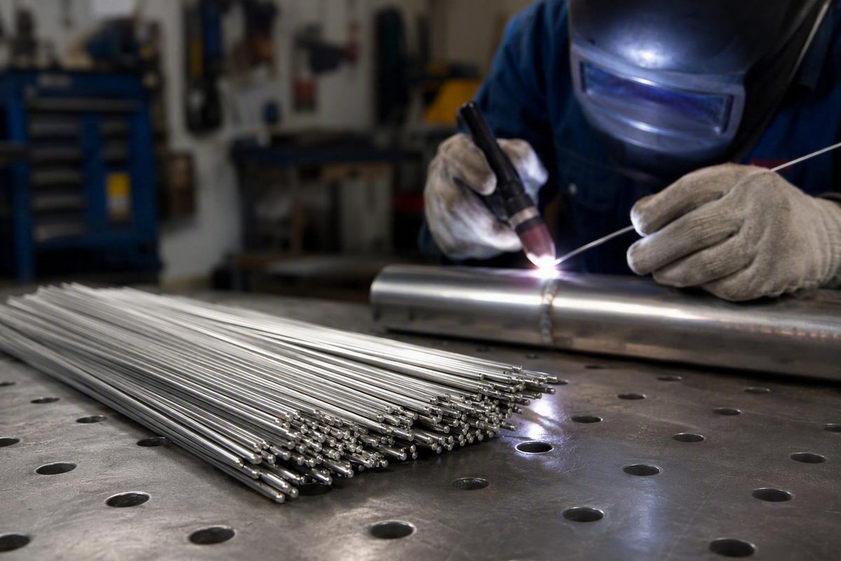
Selecting aluminum TIG welding rods is not a matter of finding the strongest alloy, the most familiar brand, or the lowest price. The correct choice begins with the exact aluminum alloy on each side of the joint.
ER4043 and ER5356 are common candidates, but neither works successfully with every aluminum alloy. Even where both may be considered, they offer different tradeoffs in puddle fluidity, cracking behavior, ductility, shear strength, anodized color, and elevated-temperature service.
This guide is an introductory screening and buying resource. It can help you compare common candidates, choose practical rod dimensions and package quantities, and audit a product listing. It cannot establish code acceptance, design strength, procedure qualification, or fitness for a critical application.
Start With the Base Alloy, Not the Rod Brand
Before recommending a rod, identify the complete alloy designation for both pieces being joined.
“Aluminum sheet,” “extrusion,” “marine plate,” and “cast aluminum” are descriptions, not complete material identifications. They do not reveal enough about composition or compatibility to support a dependable filler choice.
Use this selection sequence:
- Identify both base alloys. Check material markings, mill certificates, purchase records, drawings, or reliable material analysis. Include the temper where it affects the design or welding procedure.
- Identify any dissimilar pairing. Do not assume that a filler suitable for either alloy individually is suitable for joining the two alloys to each other.
- Check the controlling documents. Review the drawing, welding procedure specification, applicable code, engineering requirements, and the filler-selection chart accepted for the work.
- List only the permitted fillers. Eliminate incompatible or prohibited classifications before comparing desirable characteristics.
- Compare the remaining choices by service needs. Consider cracking risk, required joint performance, ductility, corrosion exposure, geometry, finishing, temperature, and post-weld processing.
- Choose the rod dimensions and package format. Diameter, length, quantity, packaging, and traceability come after alloy compatibility.
Secondary requirements can materially change the choice among otherwise permitted fillers:
- Hot-cracking sensitivity
- Required tensile or shear performance
- Ductility and toughness
- Forming after welding
- Corrosion environment
- Butt, groove, lap, or fillet-joint geometry
- Restraint and fit-up
- Post-weld anodizing
- Sustained operating temperature
- Heat treatment after welding
- Applicable fabrication and qualification requirements
Do not rely on nominal filler strength alone.
A dissimilar-aluminum joint likewise cannot be resolved by choosing whichever rod is marketed as “general purpose.”
Selection boundary: This article can screen common candidates only. The controlling drawing, code, engineering specification, filler chart, qualified procedure, equipment manual, and site rules take precedence. This informational-use boundary is also reflected in the site’s terms and safety notice.
If reliable alloy identification is unavailable, stop rather than guess—especially for load-bearing, pressure-containing, fuel, marine, transportation, or aerospace components.
What the Classification and Product Label Tell You
ER4043, ER5356, and similar designations identify filler-alloy classifications. They are not brand names, quality rankings, or declarations of universal compatibility.
Aluminum bare welding electrodes and rods are commonly sold in the context of AWS A5.10. That classification context identifies the filler-metal type, but the printed designation alone does not establish whether the filler is permitted for a particular pair of base alloys.
Products carrying the same classification may come from different manufacturers and may differ in:
- Rod diameter and length
- Package weight
- Tube, box, or other packaging format
- Identification on individual rods
- Lot control and traceability
- Available certificates
- Packaging integrity and storage history
- Product code or stock-keeping unit
Read a listing in this order:
- Classification: Confirm the complete designation, such as ER4043 or ER5356.
- Stated standards conformity: Record exactly what standard and edition the seller or manufacturer identifies.
- Diameter: Verify the dimension in the listing text, not only in an image or SKU.
- Rod length: Do not assume that every TIG rod has the same length.
- Package weight: Confirm which weight applies to the displayed price and selected option.
- Manufacturer and trade name: Distinguish the maker from the retailer.
- Product code and lot information: These help prevent mix-ups and may be required for controlled work.
- Packaging condition: Favor intact, clearly labeled packaging that protects rods from contamination.
- Documentation: Determine whether product-specific certificates and traceability records are available.
For procedure-controlled work, ask what documentation accompanies the actual lot being shipped.
The market extends beyond the two familiar classifications. One major industrial catalog lists ER1100, ER4043, ER4047, ER4943, ER5183, ER5356, ER5554, ER5556, and ER5654 among its aluminum GTAW offerings (Airgas aluminum TIG rod catalog). That range is a reminder that ER4043 and ER5356 are common, not universal.
Retail pages are product descriptions, not engineering approvals. Sponsored placement, discounts, review scores, and prominent search positions do not establish base-metal compatibility, product conformity, or completed-joint performance.
ER4043 vs. ER5356: The Main Tradeoffs
ER4043 and ER5356 are among the aluminum TIG filler classifications most consistently represented in manufacturer discussions and retailer catalogs. They are useful to compare because many welders encounter both, but the comparison is valid only after the controlling filler chart or procedure permits them for the exact base-alloy pairing.
Manufacturer guidance describes ER4043 as an aluminum-silicon filler with about 5% silicon and ER5356 as an aluminum-magnesium filler with about 5% magnesium. In compatible applications, ER4043 is generally associated with a more fluid puddle and lower crack sensitivity, while ER5356 is generally associated with greater ductility and higher typical shear strength.
| Selection factor | ER4043 | ER5356 |
|---|---|---|
| Typical composition | Aluminum-silicon filler with about 5% silicon | Aluminum-magnesium filler with about 5% magnesium |
| Commonly associated base-alloy families | Compatible heat-treatable 6XXX alloys and some compatible aluminum-silicon castings | Many compatible 5XXX alloys and some 6XXX alloys |
| Puddle behavior | Generally more fluid | Generally less fluid than ER4043 |
| Crack sensitivity | Commonly favored for lower crack sensitivity in compatible 6XXX applications | May be less favorable where the specific joint has elevated cracking risk |
| Ductility | Generally lower | Generally higher |
| Relative shear strength | Generally lower typical values | Generally higher typical values |
| Post-weld anodizing | Commonly turns gray or dark | Usually provides a closer color match |
| Elevated-temperature concern | May be considered when service exceeds the ER5356 screening threshold, if compatible | Manufacturer guidance warns against sustained elevated-temperature service above approximately 150°F or 65°C |
| Selection condition | Must first be permitted for the exact base-alloy pairing | Must first be permitted for the exact base-alloy pairing |
These are manufacturer-reported general comparisons, not guaranteed properties for a completed joint. They apply only where both fillers are otherwise compatible with the base metals (ESAB’s ER4043 and ER5356 guidance).
Where ER4043 tends to fit
ER4043 is commonly considered for compatible 6XXX-series alloys, including 6061, when the governing chart or procedure allows it. Its silicon content promotes fluidity, which can help the puddle wet and flow. It is also widely described as less crack-sensitive in compatible 6XXX applications.
That does not mean ER4043 is correct for every extrusion or every alloy beginning with “6.” The exact base metal, dissimilar pairing, joint restraint, procedure, and service conditions still control.
ER4043 also has an important finishing limitation: it commonly turns gray or dark after post-weld anodizing. An as-welded bead may look acceptable, yet the color difference can become conspicuous after the completed assembly is anodized.
Do not casually select ER4043 for high-magnesium alloys such as 5083, 5086, or 5456. The exact combination must be approved by the controlling filler chart or qualified procedure.
Where ER5356 tends to fit
ER5356 is commonly associated with many compatible 5XXX alloys and some 6XXX alloys. When both ER4043 and ER5356 are permitted, ER5356 may be favored for greater ductility, higher typical shear strength, certain fillet-weld requirements, forming after welding, or a closer color match after anodizing.
Mechanical-property comparisons must remain conditional. Published filler-metal values are not guaranteed design values for the completed joint. They do not account for the welded base metal, heat-affected zone, joint profile, discontinuities, or actual loading.
The elevated-temperature warning
Manufacturer guidance warns against ER5356 for sustained elevated-temperature service above approximately 150°F or 65°C because of its magnesium content. The same guidance identifies ER4043 as a candidate to consider above that screening threshold when it is compatible with the base alloys (ESAB’s filler-alloy comparison).
Treat this figure as a screening threshold, not as a universal instantaneous temperature ceiling. It does not establish an allowable exposure duration, stress limit, environmental condition, thermal cycle, or design life. Components operating near or above the threshold need application-specific engineering review.
A Worked Example: Choosing Filler for 6061 Aluminum
6061 is a useful decision example because manufacturer and commercial guidance identify it as a common alloy for which either ER4043 or ER5356 may be considered. That statement is not approval for a particular joint: the applicable chart, drawing, or qualified procedure must still permit both.
Once both fillers have been confirmed as permitted, compare them this way:
- Consider ER4043 when fluid puddle behavior, lower crack sensitivity, or sustained service above the cited ER5356 screening threshold is more important than post-anodizing color.
- Consider ER5356 when greater ductility, higher typical shear strength, fillet-weld performance, forming after welding, or a closer anodized color match is more important.
- Do not use “stronger is always better” as the deciding rule.
Joint type, restraint, crack risk, post-weld forming, finish, corrosion exposure, sustained temperature, and governing documents remain separate selection factors. Commercial welding guidance also discusses ER4047, ER4145, and ER4943 as candidates for some 6061 applications, but does not establish them as automatic substitutes (Weldmonger’s 6061 filler discussion).
Scenario 1: Non-anodized general fabrication
Suppose an identified 6061 assembly will remain as-welded or be painted, will not be formed after welding, and will not experience sustained elevated temperature.
Candidate to compare first: ER4043, provided the controlling selection source permits it, because its fluidity and lower reported crack sensitivity may simplify welding in a compatible joint.
Still verify: The alloy on each side, required joint performance, corrosion environment, geometry, restraint, and any drawing or procedure requirement. A heavily loaded fillet or a joint requiring greater ductility may justify comparison with ER5356.
Scenario 2: An anodized assembly
Suppose an identified 6061 assembly will be clear-anodized and visible weld color matters.
Candidate to compare first: ER5356, provided it is permitted, because it generally produces a closer color match after anodizing.
Still verify: Operating temperature, forming requirements, corrosion environment, base-alloy pairing, and governing procedure. Aesthetic preference cannot override a service limitation or engineering requirement.
Scenario 3: Sustained elevated-temperature service
Suppose an identified 6061 component will remain above the manufacturer-reported ER5356 screening threshold during normal operation rather than experiencing only a brief incidental spike.
Candidate to investigate: ER4043, but only if the exact base-alloy pairing and controlling documents permit it.
Still verify: Actual temperature history, exposure duration, loading, environment, design life, required properties, and engineering approval. The temperature threshold does not by itself qualify ER4043 for the application.
If the drawing, code, engineering document, or qualified welding procedure specifies the filler, that requirement controls. Shop preference does not supersede it.
When to Investigate Fillers Beyond ER4043 and ER5356
The following table is a list of commercially reported candidates to investigate, not a complete compatibility matrix. Every classification must be checked against the exact base alloys, service conditions, and controlling requirements.
| Classification | Alloy family or application associated with it | Why it may be investigated | What must be verified |
|---|---|---|---|
| ER1100 | 1100 and 3003 aluminum; light-gauge work | Corrosion resistance on compatible commercially pure or manganese-alloyed aluminum | Exact base alloy, required strength, thickness, and procedure |
| ER4047 | Compatible aluminum-silicon castings | Higher silicon content, fluidity, and reduced contraction or distortion | Casting composition, crack risk, service requirements, and approval |
| ER4943 | Some applications that otherwise consider ER4043 or ER4047 | Potentially higher strength while retaining useful shrinkage control | Whether substitution is permitted and whether requalification is required |
| ER5183 | High-strength 5XXX alloys such as 5083 and 5456 | Marine and transport work requiring a compatible high-strength filler | Exact pairing, corrosion service, design properties, and governing standard |
| ER5554 | Commonly associated with 5454 | Specialized compatibility with 5454 applications | Base-metal identity, service conditions, and procedure |
| ER5556 | High-magnesium alloys such as 5083 and 5456 | Higher-strength option for certain compatible 5XXX applications | Crack behavior, corrosion exposure, design requirements, and qualification |
| ER2319 | Aluminum-copper alloys such as 2219 | Specialized aerospace and high-performance work | Engineering approval, heat treatment, process qualification, and traceability |
These associations come from commercial filler guidance and identify what to research; they do not grant permission to weld every alloy in a named family (TIG filler classification guide).
ER4047 and castings
ER4047 is a higher-silicon filler commonly investigated for compatible aluminum-silicon castings. ER4043 is also associated with some compatible aluminum-silicon cast repairs.
Neither classification is a universal “cast aluminum rod.” The casting alloy must be identified first. A repair may also require assessment of contamination, porosity, previous filler, cracks, wall thickness, prior heat exposure, and the consequence of failure.
ER4943 as an alternative to investigate
ER4943 is presented in manufacturer guidance as a higher-strength alternative for some applications that might otherwise use ER4043 or ER4047. That does not establish it as an approved drop-in substitution.
Before changing filler, determine whether the drawing, customer specification, code, or qualified procedure names a specific classification.
Fillers for high-magnesium and marine alloys
For identified alloys such as 5083, 5086, or 5456, investigate compatible 5XXX fillers rather than defaulting to ER4043. ER5183, ER5356, and ER5556 may appear as candidates depending on the exact pairing and performance requirements.
Marine exposure introduces corrosion and service considerations that a generic compatibility statement cannot settle. Structural, marine, pressure, fuel, transportation, and aerospace work requires the applicable engineering and qualification controls.
Choose Diameter, Length, and Package Size for the Work
After selecting a compatible filler classification, choose a diameter that works with the puddle and joint.
Industrial catalogs commonly list aluminum TIG rods in 1/16-, 3/32-, and 1/8-inch diameters. Some classifications are also available in 5/32- and 3/16-inch sizes. Thirty-six inches is a common industrial rod length, although availability varies by classification and manufacturer (Airgas aluminum TIG rod sizes).
Shorter retail rods are also sold. Product photographs can make them look like standard industrial rods, so confirm the stated length in the listing text.
Diameter selection
Use qualitative guidance rather than a universal material-thickness chart:
- Smaller rods permit smaller, more controlled filler additions and can suit a small puddle, narrow joint, or delicate edge.
- Larger rods add filler faster and can suit larger puddles, wider joints, and heavier weldments.
Final diameter selection depends on:
- Base-metal thickness
- Joint type and included angle
- Root opening
- Fit-up and edge condition
- Welding position
- Part mass and heat sinking
- Travel speed
- Puddle size
- Required bead size
- Deposition needs
- Welder access and control
Do not convert an amperage rule of thumb into a rod-diameter rule. Machine characteristics, joint geometry, waveform controls, heat sinking, technique, and the applicable procedure all influence the usable current and filler size.
Length and handling
Long rods are common in industrial tubes and boxes, but they are not mandatory. Shorter rods may be easier to ship, store, or use in restricted spaces.
Avoid cutting or removing rods from identified packaging unless the shop has a reliable way to preserve alloy identity.
Package quantity
Retail and industrial listings show packages ranging from approximately 1 to 10 pounds, with larger quantities also available. One ER4043 listing, for example, offers 1/16-by-36-inch rods in 2- and 10-pound options and identifies plastic-tube packaging (WeldingCity ER4043 listing).
Choose quantity according to consumption and storage capability:
- Small packages can limit initial cost and storage exposure for occasional repairs.
- Medium or larger shop packages may suit routine consumption when the alloy is used often.
- Industrial quantities make sense only when inventory control, turnover, and protected storage justify them.
Buy only what you can keep clean, dry, separated, and correctly identified. A lower unit price creates no value if rods become mixed, damp, oxidized, or contaminated before use.
Do not calculate cost per pound unless the displayed price is unambiguously tied to a specific package weight. Retail pages may combine multiple options, changing prices, inconsistent titles, or photographs of a different package.
Purchasing mini-checklist
Before adding aluminum TIG welding rods to a cart, verify:
- Complete filler classification
- Rod diameter
- Rod length
- Explicit package weight
- Manufacturer and product code
- Protective packaging
- Durable alloy identification
- Stated standards conformity
- Product-specific documentation
- Lot traceability, if required
- Shipping and return restrictions
Setup, Cleaning, and Storage Matter as Much as the Label
A compatible rod can still produce poor results when the workpiece is contaminated, oxide remains in the joint, shielding is disrupted, or filler has been stored carelessly.
Manufacturer guidance describes AC with 100% argon as a common aluminum TIG baseline, gives approximately one amp per 0.001 inch of material thickness only as a rough starting heuristic, states that aluminum oxide melts at approximately three times the temperature of aluminum, and recommends allowing rods moved from another storage area at least 24 hours to acclimate before use (Hobart Brothers’ aluminum TIG setup and handling guidance).
None of those points is a universal setup prescription. Follow the power-source manual and applicable welding procedure for polarity, waveform, balance, frequency, current range, shielding-gas delivery, tungsten preparation, and cooling requirements.
Clean in the right order
A practical preparation sequence is:
- Remove oil, grease, dirt, marking residue, and other surface contaminants using the cleaner and method approved for the job.
- Follow the cleaner’s instructions and applicable shop safety controls, including ventilation and required PPE.
- After degreasing, remove oxide with a new stainless-steel brush or one dedicated exclusively to aluminum.
- Protect the cleaned joint from handling and shop contamination.
- Clean filler only when the governing procedure requires it, without losing alloy identification.
Do not use a stainless brush on steel and then move it to aluminum. Keep the aluminum brush labeled and separated from general-purpose tools.
Inadequate cleaning can contribute to porosity and lack of fusion, but cleaning is not a cure-all.
Balance energy and travel
Aluminum conducts heat away from the weld area rapidly, so starting the puddle may require substantial energy. Excessive energy or slow travel can then overheat the work and enlarge the heat-affected zone.
The objective is not simply to weld “hotter.” Use enough energy to establish fusion, maintain suitable travel, and avoid lingering unnecessarily. The acceptable balance depends on the part, equipment, and procedure.
Store filler by alloy
Good storage protects both cleanliness and identity:
- Separate rods by classification.
- Retain original labels.
- Keep partial packages covered.
- Store filler in a clean, dry area.
- Minimize temperature swings that can promote condensation.
- Never return an unidentified rod to a labeled package.
- Quarantine mixed, damp, dirty, or unmarked filler.
The acclimation period discussed above is manufacturer guidance, not a universal code requirement. Appropriate PPE, ventilation, electrical precautions, equipment instructions, and site rules remain mandatory.
Final Buying and Selection Checklist
Use this checklist before ordering or opening a package:
-
Confirm both base alloys. Record the complete designation for each side of the joint and note any dissimilar pairing.
-
Check the controlling selection source. Confirm that the filler classification is permitted by the applicable chart, drawing, code, engineering document, or qualified welding procedure.
-
Identify service and finishing requirements. Determine whether the assembly will be anodized, formed after welding, exposed to corrosive service, heat-treated, cyclically loaded, or held at elevated temperature.
-
Compare only permitted fillers. Evaluate crack sensitivity, fluidity, ductility, strength, joint geometry, anodized color, and temperature restrictions only after compatibility has been established.
-
Choose diameter for the puddle and joint. Decide whether the work favors small, controlled additions or a higher deposition rate. Account for root opening, fit-up, position, part mass, and access.
-
Verify the listing text. Require explicit statements of classification, diameter, rod length, and package weight. Do not infer them from a picture, SKU suffix, search snippet, or inconsistent link title.
-
Identify the manufacturer and product code. Confirm that the retailer is shipping the product and package represented by the listing.
-
Review the packaging. Favor protective packaging with durable alloy identification. Determine whether individual rods are marked if that matters to your inventory system.
-
Request documentation when required. For controlled or critical work, ask for the relevant certificate, lot identification, traceability, and product-specific conformity records.
-
Check shipping and return conditions. Resolve destination restrictions and return limitations before purchasing.
-
Inspect the delivery. Look for torn packaging, moisture, corrosion products, dirt, mixed rods, missing labels, and discrepancies between the order and received material.
-
Quarantine questionable filler. Do not put damaged, contaminated, damp, mixed, or unidentified rods into normal storage.
-
Match quantity to consumption. Occasional users should favor manageable packages. Routine users can compare larger quantities after accounting for turnover, segregation, and protected storage.
-
Ignore nontechnical popularity signals. Price, discounts, sponsorship, star ratings, review counts, and search position do not establish suitability. Marketplace results may be sponsored, and customer ratings do not verify alloy chemistry, conformity, or compatibility (Amazon search results for aluminum TIG rods).
-
Stop when the application exceeds general guidance. Seek qualified engineering or welding-procedure direction for unknown alloys, dissimilar joints, critical structures, pressure work, fuel systems, aerospace work, sustained elevated-temperature service, or conflicts with project documents.
The final decision sequence is straightforward: identify both base alloys, consult the controlling filler chart or procedure, compare only the fillers it permits, choose a practical diameter and package quantity, and protect the rods from contamination.
ER4043 may favor fluidity and lower crack sensitivity in compatible work. ER5356 may favor ductility, typical shear strength, and post-anodizing color. Neither is a universal answer. Unknown materials, critical service, and conflicting project requirements should be escalated rather than resolved with a retailer description or rule of thumb.
Frequently Asked Questions
Should I use ER4043 or ER5356 for 6061 aluminum?
Either may be considered only when the applicable filler-selection chart or qualified procedure permits both for the exact 6061 joint.
ER4043 may be the first candidate to compare when fluidity, lower reported crack sensitivity, or sustained elevated-temperature service matters. ER5356 may be the first candidate to compare when greater ductility, higher typical shear strength, fillet-weld performance, forming after welding, or a closer anodized color match matters.
The drawing, engineering specification, code, or qualified procedure overrides this comparison.
What diameter aluminum TIG rod should I use?
Choose diameter according to puddle size, material thickness, joint geometry, root opening, fit-up, position, heat sinking, travel speed, and deposition requirements.
A smaller rod generally permits finer filler additions. A larger rod adds material faster to a larger puddle. Do not select rod diameter solely from an amperage rule; test the permitted filler and diameter within the applicable procedure.
Can I use ER5356 when the welded part will operate above 150°F?
Do not assume that you can. Commercial and manufacturer guidance warns against ER5356 for sustained service above approximately 150°F or 65°C. Obtain application-specific engineering or procedure guidance before using it under those conditions (Weldmonger’s temperature discussion).
The threshold is not a universal instantaneous ceiling. Exposure duration, loading, environment, base alloys, and design life all matter. ER4043 may be investigated where compatible, but temperature alone does not approve it.
Which TIG filler rod should I use for cast aluminum?
Identify the casting alloy first. ER4043 and ER4047 are commonly investigated for compatible aluminum-silicon castings, but neither works with every casting.
One Harris ER4043 listing associates that filler with particular aluminum-silicon casting repairs and reports a gray post-anodized color (Harris ER4043 product information). Treat such application descriptions as starting points, not proof of compatibility.
Critical repairs require material identification and qualified technical direction.
What shielding gas and polarity are commonly used for TIG welding aluminum?
AC with 100% argon is a common baseline, but actual polarity, waveform, balance, frequency, current, gas delivery, and tungsten configuration must follow the equipment manual and applicable welding procedure (Hobart Brothers’ aluminum TIG guidance).
DC aluminum TIG methods also exist, but they involve different shielding and oxide-cleaning considerations. Do not change processes or gases based on a short general rule. Use appropriate PPE and ventilation, and follow equipment instructions and site requirements.