
Build the Right TIG Consumables Setup Without Mixing Parts
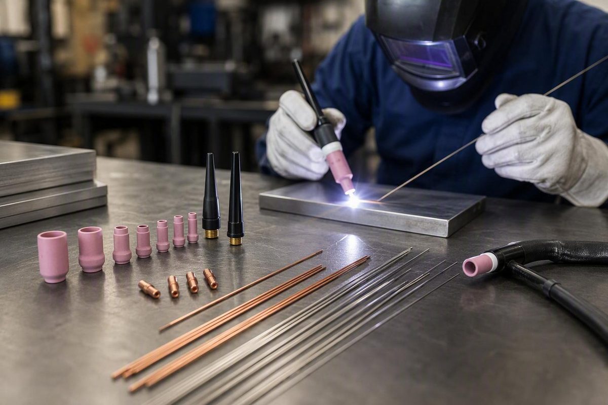
*By Cole Brandt, CWI-certified welder. *
Buying TIG welding consumables should begin with two facts: the exact torch in your hand and the work you expect to weld. It should not begin with a kit labeled “steel,” “aluminum,” “stubby,” or “universal.”
TIG parts are sold through overlapping naming systems. A listing may describe a torch family, front-end configuration, cup style, tungsten diameter, or material application without clearly identifying all of them. Parts from different systems can look similar while differing in dimensions, threads, insulators, cup systems, or seating geometry.
This guide is therefore a purchasing and compatibility-verification workflow, not a cross-brand interchange manual or welding procedure. Exact fit must come from the torch manufacturer’s documentation, and procedure-sensitive choices must follow the equipment manual, approved welding procedure, and workplace requirements.
Use this sequence:
- Identify the exact torch model and cooling configuration.
- Select tungsten composition and diameter for the validated welding setup.
- Match the collet, collet body or gas lens, insulator, and cup as one assembly.
- Match filler metal to the exact base alloy and service requirements.
- Select the approved shielding gas and compatible gas equipment.
- Compare kits by documented contents, quantities, and usable cost—not by name or price alone.
What Counts as a TIG Welding Consumable?
Gas tungsten arc welding, or GTAW/TIG, uses a non-consumable tungsten electrode to establish the arc. Shielding gas protects the electrode and weld area, while filler metal is fed separately when the joint requires it. Some joints are fused without added filler; this is commonly called autogenous welding. Miller’s TIG process overview explains the separate roles of tungsten, shielding gas, and filler metal.
“Non-consumable” describes tungsten’s role in the process. It does not mean an electrode lasts indefinitely. Contamination, erosion, repeated grinding, excessive current for the selected setup, breakage, or accidental contact with the puddle can eventually make replacement necessary.
A practical purchasing classification has three groups.
| Group | Typical items | How to treat them |
|---|---|---|
| True process consumables | Shielding gas and added filler rod | Replenished as welding consumes them |
| Electrode and replaceable torch parts | Tungsten, cups or nozzles, collets, collet bodies, gas lenses, back caps, insulators, gaskets, screens, and diffusers | Replaced after contamination, damage, loss, or loss of usable dimensions |
| Durable equipment and accessories | Complete torches, power cables, gas hoses, adapters, handles, cable covers, cases, and organizers | Purchased as equipment or accessories rather than assumed to be routinely consumed |
Retail categories do not always respect those boundaries. Commercial catalogs may place complete torches, adapters, cable covers, and cases beside cups and tungsten. Airgas, for example, separately identifies nozzles, collets, gas lenses, collet bodies, cups, back caps, insulators, gaskets, diffusers, and screens within its broad TIG torch-consumables category. That catalog organization shows how widely retailers use the word “consumables”; it does not determine how quickly any item wears out. See the Airgas TIG torch-consumables categories.
Compact TIG front-end glossary
-
Tungsten electrode: Carries current and establishes the arc without being intentionally deposited into the weld.
-
Torch head: Connects the electrode-holding and gas-delivery components to the torch body.
- Torch package: The durable assembly, commonly including a head, handle, cable, and connections.
Commercial listings include ceramic, alumina, quartz, Pyrex, and Teflon cup products. Their availability does not establish a universal performance hierarchy. Choose cup material only after confirming compatibility and the application’s requirements.
The practical distinction is simple: shielding gas and added filler are genuinely consumed by welding; tungsten and front-end pieces are replaceable service items; the complete torch and associated hardware are durable equipment.
Identify the Torch Before You Buy Anything
The model marking on the torch is the starting point for every front-end purchase. Do not identify a torch only by appearance, amperage class, handle shape, or the machine to which it is connected.
Record the following before shopping:
- Manufacturer or torch brand
- Exact model marking and suffix
- Air-, gas-, or water-cooled configuration
- Existing collet, body, lens, cup, and insulator part numbers
- Current tungsten diameter
- Standard, gas-lens, large-lens, or stubby configuration
- Connection details if buying a complete torch, cable, hose, or adapter
A common market grouping associates Series 2 components with #9 and #20 torches and Series 3 components with #17, #18, and #26 torches. Catalogs regularly organize gas lenses and collets this way; EDGE, for example, lists separate Series 2 gas lenses for 9/20 torches and Series 3 lenses for 17/18/26 torches. This is useful catalog evidence, not proof of universal interchangeability. Review the series-based organization in EDGE Welding Supply’s TIG collection.
Torch-family planning matrix
| Torch group | Common market designation | Example model labels | Start with this component family | Required verification |
|---|---|---|---|---|
| #9 / #20 | Series 2 or 2 Series | 9, WP-9, CK9; 20, WP-20, CK20 | Parts expressly documented for the exact model and selected front-end system | Manufacturer, suffix, cooling method, threads, dimensions, tungsten diameter, insulator, cup system, and part number |
| #17 / #18 / #26 | Series 3 or 3 Series | 17, WP-17, CK17; 18, WP-18, CK18; 26, WP-26, CK26 | Parts expressly documented for the exact model and selected front-end system | Manufacturer, suffix, cooling method, threads, dimensions, tungsten diameter, insulator, cup system, and part number |
Cooling method is especially important when selecting complete torches, cables, hoses, connections, and the operating setup. It remains an additional compatibility field rather than a substitute for the model number.
Why a shared series label is not enough
Two products sold under the same broad family label can still differ in:
- Thread form or diameter
- Overall length
- Shoulder or seating dimensions
- Required insulator
- Cup attachment system
- Standard versus gas-lens geometry
- Supported tungsten diameter
- Manufacturer-specific design
- Package composition or quantity
Verify the cup, insulator, body or lens, collet, and torch against the applicable manufacturer diagram and part numbers.
Do not create a cross-brand interchange chart from retailer labels. Some sellers make broad fit claims, but the supplied evidence does not establish manufacturer-approved substitutions across every brand and model.
Compatibility-verification sequence
- Read the torch marking. Inspect the head, handle, cable tag, packaging, and equipment documentation.
- Find the manufacturer’s exploded diagram or manual. Use it to identify original components and part numbers.
- Identify the current configuration. Determine whether it uses a standard body, gas lens, large gas lens, stubby conversion, or another system.
- Choose the validated tungsten diameter. This establishes the required bore size for the gripping components.
- Match the collet and body or lens. Both must accept the selected electrode diameter.
- Confirm the insulator or gasket. A change in front-end system can require a different part.
- Confirm the cup system. Match its attachment and seating design to the selected body or lens.
- Check the back cap. Verify torch-model fit and choose an approved length suitable for the work area.
- Compare part numbers and dimensions. Do this even when a seller uses familiar family labels.
- Verify package quantity. A displayed price may apply to one item, a pair, a multipack, or one selectable size.
If a listing omits a required field, ask the manufacturer or supplier before buying. A familiar family name is a search filter, not a compatibility guarantee.
Match the Complete Front-End Assembly
Think of the front end as one coordinated assembly rather than a bag of independent pieces.
A simplified rear-to-front arrangement is:
[Back cap]
    ↓ applies clamping force
[Collet surrounding tungsten]
    ↓ enters
[Torch head]
    ↓ receives
[Collet body OR gas lens]
    ↓ works with
[Correct insulator or gasket]
    ↓ supports
[Cup or nozzle]

Tungsten runs through the center toward the arc.
Shielding gas travels through the torch and exits around the tungsten.
The exact internal arrangement varies by torch. Use this diagram only as an identification aid; the manufacturer’s exploded diagram remains authoritative for assembly.
Tungsten diameter is the shared sizing decision
The selected tungsten diameter connects several purchases:
- The collet must grip that diameter.
- The collet body or gas lens must accept that diameter.
- Any specialized holder or wedge collet must support it.
- The components must belong to the correct torch family and documented configuration.
- The cup and insulator must fit the chosen standard, gas-lens, or stubby system.
It still must belong to the correct component system. Choosing the right tungsten and collet does not make an assembly usable if the lens, insulator, or cup comes from an incompatible configuration.
As an illustration, a WP-20 setup using a 3/32-inch electrode would lead a buyer toward Series 2 catalog listings. The buyer must then verify a 3/32-inch collet, a body or lens that accepts that diameter, the required insulator, and cups documented for the same front end. The 3/32-inch size is only an example seen in commercial listings and setup guidance—not a default for every application.
Standard collet body versus gas lens
It is a normal configuration for many TIG applications.
A gas lens incorporates screens or diffusing elements that alter gas distribution.
Changing to a gas lens can alter the required combination of:
- Collet or electrode holder
- Gas lens
- Insulator or gasket
- Cup
- Screens or diffusers
- Overall front-end dimensions
Retail organization reinforces the need to distinguish these systems. PrimeWeld, for example, lists separate stubby gas-lens kits for #9/#20 and #17/#18/#26 torch groups rather than one undifferentiated kit. See the series-separated catalog listings.
A kit should be a coordinated set
Before buying a gas-lens or stubby kit, confirm:
- Exact torch family and supported models
- Standard, gas-lens, large-lens, or stubby configuration
- Supported tungsten diameters
- Collet sizes and quantities
- Collet-body or gas-lens sizes and quantities
- Cup sizes and materials
- Correct insulator or gasket
- Included back caps
- Screens or diffusers
- Manufacturer and part numbers
- Availability of individual replacement components
If a listing shows an attractive cup but does not identify the lens, collet, insulator, electrode sizes, and quantities, it does not provide enough information to establish compatibility.
Pre-purchase assembly checklist
- [ ] Torch manufacturer: ________
- [ ] Exact torch model and suffix: ________
- [ ] Cooling method: air / gas / water
- [ ] Manufacturer diagram or manual checked
- [ ] Existing front end: standard / gas lens / stubby / other
- [ ] Tungsten composition: ________
- [ ] Tungsten diameter: ________
- [ ] Matching collet part number: ________
- [ ] Matching body or gas-lens part number: ________
- [ ] Correct insulator or gasket: ________
- [ ] Compatible cup system and sizes: ________
- [ ] Back-cap fit confirmed
- [ ] Relevant dimensions and threads confirmed
- [ ] Package quantity confirmed
- [ ] Individual replacements available
- [ ] Seller’s fit statement agrees with manufacturer documentation
The objective is not to make every torch use the same parts. It is to ensure that every component installed on one torch belongs to the same verified assembly.
Choose Tungsten by Application, Then Confirm the Size
Tungsten selection involves two separate decisions:
- Composition: the alloy or grade.
- Diameter: the physical electrode size.
Composition does not determine diameter, and diameter does not establish the correct composition. Both depend on the welding application.
Start with:
- Exact base metal and alloy
- AC or DC operation
- Polarity
- Expected amperage range
- Material thickness
- Joint geometry
- Machine type and waveform
- Electrode-tip preparation
- Duty cycle
- Approved procedure or manufacturer recommendation
DCEN is generally associated with steel and stainless steel, while AC is generally associated with aluminum. These are starting relationships, not substitutes for the equipment manual or a validated procedure.
Common tungsten families
Commercially available families represented in the supplied sources include lanthanated, ceriated, zirconiated, rare-earth blends, and thoriated electrodes. Their application tendencies should remain qualified:
- Lanthanated: Some commercial and manufacturer guidance describes lanthanated products for mixed AC/DC use; other guidance emphasizes DC or precision applications.
- Ceriated: Commonly discussed for lower-amperage work and arc starting at lower current.
- Zirconiated: Commonly associated with AC welding of aluminum and magnesium.
- Rare-earth blends: Sold as mixed-use alternatives, but the exact blend and manufacturer guidance matter.
- Thoriated: Historically associated with DC work. Commercial technical guidance notes that it contains low-level radioactivity, so selection, grinding, exposure control, and disposal should be governed by the product safety data sheet and applicable workplace requirements—not improvised from a buying guide. Express Weldcare’s overview identifies the tungsten families and notes the radioactivity of thoriated tungsten.
The sources do not agree on one universally versatile chemistry. One guide presents ceriated tungsten broadly, another favors lanthanated for AC/DC use, and retailers promote rare-earth blends. Those differences are a reason to follow the machine and electrode manufacturers rather than declaring one color or chemistry “best.”
Color coding should also be verified. Check the package label, electrode marking, applicable specification, and manufacturer documentation instead of identifying an unknown electrode by color alone.
Diameter follows the validated current range
Higher current generally calls for a larger-diameter electrode. An undersized electrode may overheat or lose the required tip condition. Diameter selection also has to account for low-current operation, access, polarity, grade, preparation, waveform, and duty cycle.
Published tables vary because they use different assumptions. ESAB identifies amperage, material thickness, and tungsten type as core sizing factors and recommends larger electrodes as current rises; its figures should still be treated as application guidance rather than universal limits. See ESAB’s tungsten-size selection criteria.
Use a chart supplied by the machine or electrode manufacturer for the actual combination of:
- AC or DC
- Polarity
- Tungsten grade
- Tip preparation
- Machine waveform
- Duty cycle
- Welding current
A 3/32-inch electrode is a common commercial example, but it is not the default for all TIG work. Thin sheet, micro-TIG, high-current work, automation, and specialized torch designs can require different diameters.
Preparation and contamination control
Prepare tungsten with dedicated equipment to reduce pickup from general-purpose grinding. Commercial manufacturer guidance recommends grinding lengthwise along the electrode rather than circumferentially.
If the tungsten touches the puddle or filler, stop and inspect it. Restore the electrode according to the shop’s procedure before welding resumes rather than continuing solely because the arc can still be maintained.
This guide does not prescribe dust-control methods. For any electrode—and especially a thoriated product—follow the safety data sheet, applicable occupational requirements, and the employer’s exposure-control procedure.
Select Filler Rod and Shielding Gas
Filler selection starts with the exact base-metal grade, not a broad label such as “steel,” “stainless,” or “aluminum.”
Also identify:
- Joint design
- Material thickness
- Service temperature
- Corrosion environment
- Required strength and ductility
- Post-weld treatment
- Applicable code or customer specification
- Welding procedure specification, if one applies
- Filler classification and traceability requirements
A “stainless kit” may be a convenient retail category, but the label does not show whether its filler matches a particular stainless grade, service environment, or approved procedure.
Filler-metal examples, not universal substitutions
Common examples in commercial guidance include:
- ER70S-6 for some ordinary mild-steel work
- ER308 or ER308L for some 304 stainless applications
- ER4043 for some common aluminum work
These are examples, not universal matches. The correct filler can change with base-alloy chemistry, dilution, loading, crack sensitivity, corrosion exposure, heat treatment, appearance requirements, and the governing procedure. YesWelder presents these classifications as common examples tied to particular mild-steel, 304-stainless, and aluminum applications.
For critical or controlled work, purchase filler against the drawing, WPS, engineering instruction, or another approved filler-selection document.
Filler diameter and material thickness
Thinner material generally uses smaller tungsten and filler rod, while increased thickness and current tend to call for larger sizes. A universal diameter chart would ignore important variables such as:
- Joint gap and bevel
- Root opening
- Position
- Travel speed
- Required deposition
- Pulse settings
- Manual versus mechanized feeding
- Heat-input restrictions
- Procedure limits
Select diameter from the applicable procedure or a manufacturer chart tied to the actual work.
When filler is omitted
Autogenous TIG joins the work by fusion without separately added filler.
Do not omit filler merely because the edges can be fused. Suitability depends on the alloy, thickness, joint design, service conditions, and metallurgical requirements. Confirm that the applicable procedure permits an autogenous weld.
Shielding-gas selection
Argon is the usual starting shielding gas for common TIG work. It shields the hot tungsten and molten weld area from atmospheric contamination and is commonly used across steel, stainless steel, and aluminum applications.
Helium can increase heat input, penetration, and travel speed. Argon-helium mixtures combine characteristics of the two gases and may be considered for thicker or highly conductive materials. These are application-specific choices, not automatic upgrades. ArcCaptain’s gas overview describes argon, helium, and argon-helium characteristics.
This guide does not recommend hydrogen- or nitrogen-containing blends. Their suitability depends strongly on alloy and procedure, and the supplied evidence is not sufficient for generalized instructions.
Filler and gas buying checks
For filler rod, verify:
- Exact classification and applicable specification
- Diameter
- Package identity
- Manufacturer and lot information where traceability is required
- Clean, undamaged packaging
- Surface condition
- Approval under the job’s procedure or controlled materials list
For shielding gas and delivery equipment, verify:
- Exact gas or approved mixture
- Required purity
- Cylinder ownership, lease, or exchange arrangement
- Regulator and flowmeter compatibility
- Hose and fitting compatibility
- Cylinder size appropriate to the work
- Applicable workplace requirements for handling, securing, storage, and leak checks
Never identify an unmarked filler rod by appearance. Keep filler classifications separated and labeled from receiving through use.
Kits Versus Individual Parts: Compare Contents, Not Names
A kit can be the simplest way to establish a documented standard, gas-lens, or stubby configuration. Individual components can be more practical when you already know which cups, collets, and bodies your work uses most often.
Neither method is inherently better.
When a kit makes sense
A kit can be practical when:
- Converting a known torch to a documented gas-lens or stubby system
- Equipping a new torch family
- Trying several cup sizes within one compatible system
- Creating a field box with complete matched assemblies
- Replacing a mixed or unidentified collection of loose parts
The principal purchasing risk is paying for unused sizes or assuming every item in the box works with every electrode diameter shown in the listing.
When individual parts make sense
Buying separately can be preferable when:
- The shop has standardized one or two tungsten diameters
- Existing cups and insulators remain usable
- Only one component category needs replenishment
- A controlled parts list specifies exact manufacturer numbers
- A kit contains unwanted cup materials or duplicate sizes
- Individual replacement availability matters more than assortment breadth
Kit-comparison worksheet
| Comparison field | Kit A | Kit B | Individual-parts basket |
|---|---|---|---|
| Exact torch family and model | |||
| Standard, stubby, or gas lens | |||
| Supported tungsten diameters | |||
| Collet sizes and counts | |||
| Body or lens sizes and counts | |||
| Cup sizes and counts | |||
| Cup materials | |||
| Insulators or gaskets included | |||
| Back caps included | |||
| Screens or diffusers included | |||
| Manufacturer and part numbers | |||
| Individual replacements available | |||
| Total documented component count | |||
| Price snapshot date | |||
| Shipping and tax treatment | |||
| Cost per usable component |
Calculate cost per usable component rather than simply dividing price by the advertised piece count. Components in diameters or systems your shop never uses do not add practical value.
What retailer prices do—and do not—show
The supplied retailer captures do not include a reliable common access date, so the figures below should be treated only as historical, point-in-time examples.
One captured collection listed #9/#20 material-labeled kits from $21.99 to $64.99. Those prices can change and do not establish current availability or value. See the collection supporting the low-$20 through mid-$60 examples.
A separate specialty-kit collection displayed products from $62.99 to $399.99, including several gas-lens and combination kits. Those figures likewise do not establish current prices, contents, or relative performance. See the Weldmonger collection supporting the specialty-kit examples.
Price differences may reflect component count, supported diameters, brand, specialty cups, lens size, included back caps, storage, or assortment breadth. The listings do not prove that a higher-priced kit produces better welds, lasts longer, or offers better value.
A worked listing-screen comparison illustrates the information gap:
| Field | Low-price material kit | Specialty kit | Individual-parts basket |
|---|---|---|---|
| Displayed historical price | Documented | Documented | Not fully calculable from supplied listings |
| Exact contents | Not established by collection page | Often incomplete on collection page | Must be assembled from individual product pages |
| Supported diameters | May be omitted | May be omitted | Must be verified part by part |
| Replacement availability | Unknown from collection page | Unknown from collection page | Potentially clearer, but still requires verification |
| Cost per usable component | Cannot be calculated | Cannot be calculated | Cannot be calculated until all compatible parts and quantities are priced |
| Purchase conclusion | Insufficient information | Insufficient information | Incomplete basket |
The correct result is not “buy the cheapest” or “buy the premium kit.” It is insufficient information until compatibility, contents, quantities, and replacement availability are documented.
Collection pages can also show volatile or contradictory availability labels. Verify the product page and obtain seller confirmation before relying on stock information.
Material labels such as “steel,” “stainless,” and “aluminum” are equally limited. They may describe the intended assortment, but they do not replace checks for torch fit, tungsten diameter and composition, filler classification, gas, polarity, or procedure.
Build a Practical Spare-Parts Inventory
A useful TIG inventory is organized around validated setups rather than retailer categories. Stock depth should come from actual usage, supplier lead times, job criticality, and acceptable downtime—not a universal quantity.
Occasional users
An occasional user’s inventory should cover the torch and materials actually used:
- Matched cups
- Matching collets
- Matching collet bodies
- Correct insulators or gaskets
- Back caps in approved, useful lengths
- Tungsten in the required compositions and diameters
- An optional complete gas-lens configuration
- Filler for the exact alloys welded
- Sufficient approved shielding gas
- Clearly labeled storage for small components
A small set of fully compatible components is generally more useful than a broad assortment containing unidentified or irrelevant sizes.
Mobile welders
Field work makes identification errors costly. Organize complete front-end sets by:
- Torch family
- Exact torch model
- Tungsten diameter
- Standard or gas-lens configuration
- Procedure or base-material assignment where applicable
Keep each set together instead of mixing all collets, lenses, cups, and insulators in one compartment. Carry appropriate spares for fragile or easily misplaced pieces, such as cups, screens, gaskets, and insulators, without assuming a universal replacement rate.
A field label might read:
WP-20 / Series 2 / 3/32 in / gas lens / approved cup set
That label identifies a configuration more effectively than “TIG parts.”
Production shops
Production inventory should be controlled by documentation. For every approved setup, record:
- Manufacturer
- Exact part number
- Description
- Torch model
- Front-end system
- Tungsten composition and diameter
- Package quantity
- Approved substitutions
- Supplier
- Typical lead time
- Internal usage history
- Reorder point
- Applicable WPS or work instruction
Set reorder points from the shop’s consumption records and supply lead times. Do not infer stock requirements from the size of a retailer’s catalog.
Separate and clearly label tungsten compositions and diameters. Apply the same discipline to filler classifications and diameters. Unknown rods and electrodes should not enter controlled work based on visual identification.
Receiving checklist
- [ ] Match the purchase order to the package
- [ ] Verify manufacturer and part number
- [ ] Verify torch family and exact model fit
- [ ] Verify tungsten diameter
- [ ] Verify front-end system
- [ ] Check relevant dimensions and threads
- [ ] Count the package
- [ ] Inspect cups, screens, threads, and sealing surfaces for damage
- [ ] Confirm filler classification and diameter
- [ ] Confirm labels and required traceability information
- [ ] Quarantine unidentified or inconsistent material
- [ ] Update the controlled parts list and bin label
Catalog breadth is not evidence of quality. A retailer may show hundreds of products because it combines manufacturers, models, and overlapping filters. Buy against the controlled parts list rather than the category count.
Troubleshoot the Setup Before Blaming the Consumable
A new cup, lens, or electrode will not correct every TIG problem. Before replacing parts indiscriminately, return to a known baseline and inspect the complete setup.
| Symptom | Checks to make first |
|---|---|
| Arc wandering or instability | Tungsten contamination and preparation; damaged tip; composition and diameter; current range; polarity; collet fit; body or lens fit; work-return circuit; machine manual |
| Rapid tungsten damage or burnback | Polarity; current versus diameter and grade; gas coverage; post-flow; loose or incorrectly sized parts; contamination; puddle contact |
| Porosity | Base-metal and filler cleanliness; gas identity and supply; leaks; hose and regulator condition; drafts; cup seating; cracked cup; gas-lens assembly; flow |
| Dark or discolored weld | Gas coverage; leaks; cup position; drafts; contaminated material or filler; post-flow; tungsten extension; additional shielding required by the procedure |
| Weak or uneven shielding | Cylinder supply; regulator and hose condition; lens or screen assembly; gasket condition; cup and insulator fit; drafts; flow setting |
Unstable arc or damaged tungsten
Begin with the electrode:
- Confirm its composition and diameter.
- Verify polarity and machine mode.
- Compare current with the applicable manufacturer chart.
- Inspect the electrode for contamination or damage.
- Restore the required tip preparation.
- Confirm that the collet and body or lens match the diameter.
- Assemble and tighten the components according to the torch documentation.
- Check the work-return circuit and equipment connections.
- Return machine settings to the documented baseline.
Repeated tungsten damage can result from an electrical or setup error rather than defective electrode material.
Porosity, dark welds, and discoloration
Check both cleanliness and shielding integrity:
- Clean the base material according to the approved procedure.
- Inspect the filler rather than assuming it is clean.
- Confirm that the cylinder contains the intended gas.
- Check hoses, fittings, regulator, and torch connections.
- Inspect the cup for damage and correct seating.
- Verify that required screens and diffusers are installed correctly.
- Protect the weld area from drafts.
- Confirm that electrode extension and torch position match the validated setup.
- Determine whether the procedure requires backside, trailing, or enclosure shielding.
Insufficient flow can reduce shielding. Excessive flow can also be disruptive by creating turbulence or drawing surrounding air into the shielding stream. Commercial guidance differs substantially on starting values, so neither a fixed flow range nor a cup-number formula should be treated as universal. Hardware, lens design, cup geometry, drafts, position, and extension all affect the result. Weldmonger’s settings discussion treats flow values as setup-dependent starting guidance.
Post-flow
Too little may leave the electrode insufficiently protected, but no universal time applies across all machines, currents, electrode sizes, torches, and procedures.
Use the equipment manual or validated procedure for the starting value, then troubleshoot gas delivery and timing as a system.
Escalation path
If the basic checks do not resolve the defect:
- Replace visibly cracked, deformed, contaminated, or otherwise damaged parts.
- Restore the manufacturer’s original front-end configuration.
- Return to documented baseline settings.
- Use correctly identified tungsten, filler, and shielding gas.
- Make a test weld on properly prepared material if the procedure permits.
- Consult the equipment manual and manufacturer’s exploded diagram.
- Escalate to the applicable WPS, welding supervisor, inspector, or another qualified authority.
Safety
Welding involves hazardous electrical current, fumes, ultraviolet radiation, hot materials, and compressed-gas equipment. The Welder Facts notice assumes appropriate PPE and ventilation and states that equipment manuals and site rules override generic article guidance. Read the site’s informational-use and safety notice.
This article is not a substitute for occupational-safety rules, product safety data sheets, cylinder-supplier instructions, equipment manuals, or employer procedures. Commercial gas guidance supports securing cylinders, using compatible regulators, checking for leaks, providing ventilation, and wearing appropriate PPE, but the controlling requirements must come from the applicable authority and workplace. See the cited gas-handling overview.
Are TIG consumables interchangeable between #9/#20 and #17/#18/#26 torches?
Not as a general rule. The market commonly groups #9/#20 torches under Series 2 and #17/#18/#26 torches under Series 3, but those labels identify different catalog families. A component may differ in dimensions, thread, insulator, cup system, or electrode bore even if it looks similar.
Some documented stubby conversions intentionally use a coordinated combination of components across familiar family boundaries. Treat those as complete manufacturer-specified systems, not evidence that loose parts are universally interchangeable.
Verify the exact torch model, front-end configuration, tungsten diameter, dimensions, and manufacturer part numbers.
Is tungsten really a consumable in TIG welding?
Technically, TIG uses a non-consumable tungsten electrode because the electrode establishes the arc rather than being intentionally deposited into the weld.
In purchasing practice, tungsten is commonly grouped with consumables because contamination, erosion, puddle contact, breakage, and repeated grinding can eventually make replacement necessary. It is best described as a non-consumable electrode that functions as a replaceable service item.
What should a basic TIG consumables kit contain?
A useful basic kit should contain parts for one identified torch family and the tungsten diameters actually used:
- Cups
- Matching collets
- Matching collet bodies or gas lenses
- Correct insulator or gasket
- One or more compatible back caps
- Properly identified tungsten
Filler rod and shielding gas should be selected separately for the exact materials and approved procedure. A gas-lens or stubby conversion kit should state the supported torch models, electrode sizes, cup system, included insulator, and quantity of each component.
Is a gas lens better than a standard collet body?
Not universally. A gas lens can provide broader shielding coverage or accommodate greater tungsten extension, which may help in particular access or shielding conditions.
A standard collet body remains appropriate for many jobs and may provide a more compact configuration. The correct choice is the one documented for the torch and suited to the joint, cup arrangement, shielding requirement, and validated procedure.
Changing systems may require a coordinated lens, insulator, cup, and related components rather than one replacement part.
What shielding gas is normally used for TIG welding?
Argon is the usual starting gas for common TIG welding. Helium can provide greater heat input, penetration, and travel speed, while argon-helium mixtures combine characteristics of both gases. Those alternatives are application-specific.
Select gas according to the exact alloy, thickness, position, equipment, and validated procedure. Verify purity, regulator and fitting compatibility, gas-delivery condition, cylinder requirements, and the flow setting specified for the actual torch and environment.
At the counter or online, finish with the same purchase sequence:
- Identify the exact torch model and cooling configuration.
- Select tungsten composition and diameter for the approved polarity, machine, current range, and work.
- Match the collet, body or gas lens, insulator, cup, and back cap as one verified assembly.
- Verify filler against the exact base alloy, joint, service requirements, and procedure.
- Select the approved shielding gas and compatible delivery equipment.
- Compare kits with individual parts by documented contents, usable quantities, replacement availability, and unit cost.
Fit and procedure come before brand or price. Equipment manuals, manufacturer diagrams, validated welding procedures, PPE requirements, occupational-safety rules, and site controls override generic guidance.