
Choosing the Right Bead Motion for the Joint in Front of You
Permitted weave width may be set by the welding procedure, consumable classification, alloy, position or project specification.
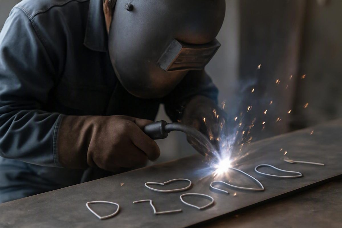
Welding patterns are best understood as puddle-control methods, not decorative recipes. A stringer, zigzag, crescent, circle, triangle, figure-eight, whip, or J motion changes where and when weld metal is placed. It does not, by itself, determine strength, penetration, heat input, or acceptance.
The right decision begins with the approved welding procedure specification (WPS). From there, consider the welding process, consumable, transfer behavior, joint geometry, material and thickness, position, pass objective, settings, and the welder’s ability to maintain a controlled pool.
This is an introductory overview of common tendencies. It is not a production-ready procedure, a code interpretation, a qualified pattern assignment, or a substitute for consumable-specific instructions.
What welders mean by a welding pattern
A weld bead is deposited weld metal in or on a joint. A bead-manipulation pattern describes the path followed by the torch, gun, tungsten, filler rod, or stick electrode while the welder advances along that joint.
The two broad categories are:
- Stringer bead: Travel proceeds mainly along the joint without appreciable transverse oscillation.
- Weave bead: The electrode or torch moves from side to side while advancing, generally producing a broader deposit.
A stringer is not necessarily perfectly motionless. A welder may make small corrections to maintain arc length, work angle, or puddle position. The distinction is that there is no deliberate, appreciable side-to-side weave intended to widen the bead.
A weave deliberately redistributes time and weld metal across the joint. Its path may be angular, curved, circular, stepped, or asymmetric. Width and dwell can be very limited or pronounced, but the pattern name alone defines neither one. These broad stringer and weave descriptions recur across instructional sources, although application advice varies by process and author (YesWelder’s overview of weave beads).
Informal welding-pattern names are not used consistently. One instructor’s crescent may resemble another instructor’s C-weave or semicircle. “J,” “U,” “whip,” “step,” and “stutter step” can describe overlapping motions, and the same term may refer to different techniques in different processes. Treat the name as a rough description of hand movement, not a complete welding instruction.
Bead manipulation is also different from weld sequencing:
- Bead patterns describe movement while an individual bead is being deposited.
Sequencing concerns where and in what order welds are made, often to manage contraction or distortion. Manipulation controls the active puddle and placement of weld metal within one bead. A project may specify both.
Rather than treating one fixed hierarchy as universal, use this as a practical check sequence:
- Identify the code, contract, drawing, project, and site requirements that apply.
- Read the approved WPS and supporting work instructions.
- Check the consumable manufacturer’s data sheet.
- Review the equipment manual and site safety rules.
- Use general instructional material only within those boundaries.
Actual precedence depends on the governing documents and the authority responsible for the work. If two instructions conflict, stop and obtain clarification rather than choosing whichever general rule seems familiar.
Welder Facts states that its articles are informational and that equipment manuals and site rules override article guidance. Its notice also identifies electrical current, fumes, and ultraviolet radiation as welding hazards requiring suitable protection and ventilation (Welder Facts terms and safety notice).
Stringer or weave: the first practical decision
A stringer places weld metal along a relatively narrow path. It is a common starting point when the joint is narrow, the material is thin, precise placement matters, or gravity makes a large molten pool difficult to control. Limited transverse movement also makes it easier to see how travel speed, angle, arc length, and settings affect the bead.
A limited weave covers more width by moving across the joint. When the procedure permits it, that motion may help fill a wider groove, bridge a suitable gap, organize sidewall placement, or distribute metal during selected positional, fill, and cap passes.
For stick welding specifically, Miller says material 1/4 inch thick or thinner typically does not require weaving and that a straight bead is often sufficient. That is an SMAW guideline, not a universal thickness boundary for GMAW, FCAW, or GTAW. The same guide recommends limited manipulation for wider deposits and multiple passes or stringers when more area must be covered (Miller’s stick-welding technique guide).
The practical comparison is not always “straight versus wide.” For a joint that cannot be filled with one narrow bead, the real choice may be one qualified weave versus several stringer passes.
Multiple stringers can offer:
- Deliberate placement of each bead
-
A smaller active puddle
-
More opportunities for required interpass cleaning
-
Compliance where weave width is restricted
A limited weave can offer:
- Wider coverage in one pass
- Controlled distribution of metal across a groove or fillet
- Sidewall pauses without separate starts and stops
- A practical fill or cap technique in some approved procedures
Neither approach is automatically faster or better. A weave may cover more joint width per pass, but effective travel along the joint can be slower because the torch follows a longer path. Multiple stringers add starts, stops, cleaning, and separate passes. The production tradeoff depends on deposition rate, joint volume, interpass requirements, accessibility, permitted technique, and the qualified procedure.
Weaving also does not inherently reduce heat input. Moving the arc across a wider area changes heat distribution, but slower forward progression or prolonged dwell may increase thermal exposure. Manual-weaving guidance likewise warns that slower weave travel can increase heat input and emphasizes staying ahead of solidified slag rather than weaving over it (Smooth Robotics’ manual and robotic weaving overview).
Do not adopt a universal weave-width limit from an informal ratio. Published recommendations conflict, and some are explicitly tied to SMAW electrode diameter. The permissible width may instead be controlled by the WPS, consumable classification, wire instructions, alloy, position, or project specification.
A sound decision sequence is:
- Read the WPS. Determine whether stringers, weaving, or a maximum bead width is specified.
- Identify the process and consumable. Solid wire, flux-cored wire, stick electrodes, and TIG filler systems respond differently.
- Assess the joint. Look at groove width, root opening, access, sidewalls, backing, fit-up, and required bead placement.
- Account for position. Decide how gravity will affect the pool and, where present, slag.
- Define the pass objective. A root, fill, and cap do not necessarily need the same movement.
- Choose the smallest controlled motion that works. Add oscillation only when it serves a placement or puddle-control purpose.
- Validate the result. Judge it against the applicable acceptance requirements, not ripple appearance alone.
Common welding patterns and how the motions differ
The following table describes common welding patterns as motion families. “Typical purpose” means a recurring instructional use, not a universal assignment.
The difficulty column refers only to the relative hand-path coordination a learner may experience under otherwise comparable conditions. Actual difficulty changes with process, consumable, position, access, joint, and pass type. Instructional sources describe many of these motions but disagree on some applications, reinforcing the need for procedure-specific approval (WeldGuru’s comparison of common welding patterns).
| Pattern | Hand path | Typical purpose | Relative coordination demand | Common cautions | Process or procedure limitations |
|---|---|---|---|---|---|
| Stringer | Advance along the joint without intentional transverse oscillation | Narrow beads, focused placement, roots or multipass work where specified | Lower | Inconsistent speed, angle, arc length, or stick-out can still produce poor shape and tie-in | Broadly applicable, but settings and technique remain process-specific |
| Zigzag | Cross from side to side with relatively direct diagonal transitions | Wider fills, sidewall placement, and some vertical-up or cap work | Moderate | Excessive width, slow center crossing, or long edge dwell can enlarge the pool or contribute to undercut, overlap, or slag problems | Width and dwell must be permitted by the WPS and consumable instructions |
| Crescent or C-weave | Make connected curved sweeps while progressing | Smooth distribution across a groove or fillet; an alternative to angular movement | Moderate | Curved travel can become too wide or slow; rounded motion does not prove fusion | Terminology varies and the motion is not inherently superior to a zigzag |
| Circular | Advance through small, overlapping circles | Selected fills, surfacing, or situations requiring continuous puddle redistribution | Moderate to high | Added movement raises coordination demands; slow circles can produce excessive buildup | Suitability varies strongly by process, position, joint, and procedure |
| Triangle or inverted V | Move between two side points and a forward or central point | Organizing sidewall pauses and center movement in some vertical-up techniques | Moderate | Lingering at every point can overfill the pool; poor side control can leave deficient placement | Common as an instructional vertical-up method, not a universal requirement |
| Straight-stepped | Progress through short, incremental side-to-side steps | Selected fill and cap work requiring ordered placement | Moderate | Uneven step length or rhythm creates inconsistent reinforcement and toes | More often associated with fill or cap work than with a universal root technique |
| Figure-eight | Repeatedly cross the center in alternating loops | Broad, coordinated placement in selected cover or fill applications | High | The puddle may move ahead of the arc at the toes, creating overlap or cold-lap risk | Assignments vary widely; use only when the process and procedure support it |
| Whip | Move forward out of the pool and back toward it in repeated progression | Pool control with some fast-freezing SMAW electrodes and selected root practices | High | Poor timing can leave irregular penetration, trapped slag, excessive crown, or an unstable arc | Particularly associated with certain fast-freezing stick electrodes; not generic MIG, FCAW, or TIG advice |
| J motion | Use an asymmetric loop or whip that spends more time on one side | Extra placement on one side in selected hot, fill, or root-related techniques | High | A long loop can create uneven buildup or increase slag-entrapment risk | Meaning and use vary sharply by process, pass, electrode, and procedure |
A stringer demands less path coordination, but it is not automatic. Keep the required work and travel angles consistent, maintain the proper arc length or contact-tip-to-work relationship, and advance at a speed that keeps the arc correctly positioned on the active pool.
In a zigzag, a recurring instructional rhythm is side, prompt center crossing, opposite side, prompt return. Brief side pauses may support toe or sidewall placement. The center is commonly crossed more quickly because dwelling there tends to increase central buildup without necessarily improving sidewall fusion.
A crescent seeks similar distribution through curved rather than sharp directional changes. Some welders find a curved rhythm easier to repeat; others obtain better control from a direct zigzag. The useful pattern is the one that preserves the required angles, width, speed, and puddle position.
With small circles, every loop adds distance and coordination. The movement must continue progressing along the joint. Repeatedly circling in nearly the same location slows forward travel and may accumulate reinforcement.
A triangle or inverted V can provide a repeatable map for vertical-up work: pause briefly where sidewall placement is needed, then move promptly through the center. It is a timing framework, not proof of root penetration or sidewall fusion.
A straight-stepped pattern divides movement into short increments rather than continuous curves. Instructional descriptions commonly connect it with fill and cap work. Calling it a “step” does not define the required length, width, pause, or deposition.
A figure-eight repeatedly crosses the bead center. That can distribute metal broadly, but it asks the welder to coordinate direction, speed, toe placement, and progression simultaneously. If molten metal rolls ahead of the arc at a toe, a smooth-looking surface may hide deficient fusion.
A whip is most defensible as a process- and electrode-specific technique. It is especially associated with fast-freezing SMAW electrodes and some root-pass practices. A gun motion that resembles whipping does not establish that the same timing or purpose is appropriate for solid-wire MIG, FCAW, or TIG.
A J motion is asymmetric: its longer loop or whip places more time or metal toward one side. Instructional sources connect the term with different passes and joints, which is precisely why the name cannot substitute for a procedure. In slag-producing work, an excessive loop may cause the arc to lose access to the leading pool and can contribute to slag entrapment.
No pattern should be ranked by strength based on its drawing. Penetration and weld performance depend on the complete system: joint preparation, process, filler metal, electrical parameters, travel rate, arc position, technique, and resulting fusion.
Choose the motion by position, joint, and pass
Gravity changes puddle behavior. A motion that is manageable in the flat position may create sag, rollover, or loss of control when turned horizontal, vertical, or overhead.
Flat position. Both stringers and qualified limited weaves are possible. A flat multipass butt joint may use slight side-to-side movement with controlled pauses at the toes. If the groove is wider than one permitted bead, several stringers may provide clearer placement and cleaning than one broad weave.
Horizontal position. The pool tends to sag toward the lower side of the joint, so avoid making it larger than necessary. Work angle, arc placement, travel speed, and deposition must counter that tendency. Some instructional sources discourage horizontal oscillation because of overlap or cold-lap concerns, while others describe limited horizontal weaving. That disagreement is a reason to follow the process-specific WPS rather than impose a blanket ban.
Vertical-up. Limited zigzag, crescent, triangle, or inverted-V movement is commonly taught when the procedure permits weaving. The usual objective is to establish each side, pause briefly for placement, and cross the center promptly enough to avoid an oversized pool. The arc must remain directed toward the intended fusion area rather than merely moving molten metal over it.
Vertical-down. Downhill progression is commonly faster. Manufacturer MIG guidance associates it with thinner material and some specific open-root work, whereas vertical-up is associated with greater thermal exposure and penetration. These are general tendencies, and vertical-down must not replace vertical-up without procedural authorization (Bernard and Tregaskiss MIG position guidance).
Overhead. Favor a small, controllable pool, limited bead width, and minimal weaving. Faster controlled advancement may help prevent the pool from becoming unnecessarily large, but “faster” does not mean outrunning fusion. Use the approved settings and travel rate for the process and joint.
Joint type matters because it changes access, work angle, required fusion faces, and where weld metal must be placed:
- A butt or groove joint may require root access followed by deliberate sidewall filling.
- A T-joint requires attention to both members and the root of the fillet.
- A lap joint has unequal edges and may require careful work-angle control to avoid washing metal onto an unfused surface.
None has a universally best welding pattern. Choose movement according to the surfaces that must be fused and the pool behavior produced by the actual process.
Pass purpose adds another filter:
- Root pass: Prioritize root access, root consistency, joint preparation, and process-specific arc control. Open-root whip advice for one stick electrode must not be transferred automatically to solid-wire MIG, FCAW, or TIG.
- Fill pass: Use approved stringers or a limited weave according to groove width, required placement, slag control, and thermal requirements.
- Cap pass: Control both toes and final reinforcement. Brief side pauses may support placement, but prolonged dwell can contribute to overlap, excessive reinforcement, or undercut beside the cap.
The same joint may therefore use a different motion for each pass. “This is a pipe weld” or “this is vertical” does not provide enough information to select a pattern.
Why process and consumable matter more than the pattern name
The same hand sketch behaves differently when the arc, filler delivery, shielding method, and slag system change. MIG, flux-cored, stick, and TIG advice should not be treated as interchangeable.
Solid-wire GMAW or MIG
For solid-wire MIG, motion works together with transfer mode, wire type and diameter, shielding gas, contact-tip-to-work distance, travel angle, joint geometry, wire-feed speed, and travel speed. The available evidence does not support assigning one pattern to each transfer mode, so transfer-specific instructions should come from the approved procedure and consumable or equipment documentation.
That does not make broad weaving automatically suitable. A large fluid pool can still move ahead of the arc or overlap a toe without adequate fusion.
FCAW
First determine whether the flux-cored consumable produces slag. Follow its specified polarity, shielding, stick-out, travel orientation, and technique.
In slag-producing FCAW, manipulation should keep the arc on the active leading pool and avoid weaving over slag. Remove slag and perform interpass cleaning as required by the WPS and consumable instructions before covering a completed pass.
Small, controlled movement is often easier to manage than an elaborate loop, but the permitted technique remains consumable- and procedure-specific.
SMAW
Stick-welding technique can be organized through CLAMS:
- C: Current
- L: Length of arc
- A: Angle of electrode
- M: Manipulation of electrode
- S: Speed of travel
Manipulation is only one of the five. Electrode classification affects arc behavior, slag characteristics, freezing rate, polarity, and suitable technique. A motion used with a fast-freezing electrode may be unsuitable for a more fluid, slag-heavy electrode.
Whipping is especially associated with certain fast-freezing SMAW electrodes. It should not be generalized into a standard technique for every stick electrode, much less every wire process or TIG application.
GTAW or TIG
Joint design, position, base metal, filler practice, and travel speed govern whether any transverse adjustment is useful.
A list assigning elaborate patterns to TIG joints is less useful than maintaining control of the torch and filler while following the qualified procedure. Do not import SMAW whipping or slag-management advice into TIG merely because the hand path looks similar.
Push and drag are orientations, not patterns
A push angle points the electrode or gun ahead in the direction of travel. A drag angle points it back toward the completed bead. Either orientation can accompany straight travel or, where allowed, an oscillating path.
The supplied MIG guidance associates pushing with a flatter, wider profile and dragging with a narrower profile and greater penetration. Slag-producing processes are generally dragged to help keep slag behind the pool, although procedure-dependent exceptions occur, including some vertical-up work. Excessive angle may also impair shielding coverage. Treat these as starting tendencies and follow the filler-material data sheet when informal rules conflict with wire- or electrode-specific instructions (Productive Robotics’ push-versus-drag guidance).
Control the puddle, not just the drawing
A named path is only one variable in the weld. The resulting bead is shaped by the interaction of:
- Current
- Voltage
- Wire-feed speed
- Arc length or contact-tip-to-work distance
- Travel speed along the joint
- Work and travel angles
- Oscillation width
- Dwell at the center or sides
- Joint preparation and fit-up
- Consumable behavior
- Position and gravity
This is why copying another welder’s hand path often fails. If the settings, electrode, stick-out, joint gap, position, or travel rate differ, the same apparent movement can create a different pool.
Center crossing and edge dwell
Quicker center travel with brief edge dwell is common weaving guidance because the intended result is controlled sidewall or toe placement without accumulating excessive metal in the middle. The word brief matters.
Too little time at a side may leave inconsistent placement or poor tie-in. Too much may enlarge the pool, pile up reinforcement, wash metal beyond the active fusion area, or contribute to overlap or undercut depending on arc position, heat, angle, and travel speed.
Travel speed
Travel that is too slow can produce a wide or convex bead and excessive thermal exposure. Depending on the process, material, joint, and pool position, it may also contribute to cold lap, poor fusion, or burn-through.
Travel that is too fast can produce a narrow or highly crowned bead, underfill, undercut, reduced penetration, or poor toe tie-in. The correction is not automatically to change patterns. First determine whether the arc is correctly positioned on the pool and whether the settings match the required deposition and speed.
For SMAW, Miller recommends treating current, arc length, electrode angle, manipulation, and speed as a coordinated system. Its guidance favors a tight, controlled arc and selecting current from the electrode manufacturer’s operating range, but these are stick-specific starting principles rather than mandatory production settings for every application (Miller’s CLAMS guidance).
Angle and shielding
Push and drag angles alter arc position, bead profile, and apparent penetration. Excessive travel angle may direct the arc away from a fusion face, make the pool harder to read, and impair shielding coverage in gas-shielded processes.
Position and visibility
Set up the work so the motion can be repeated without excessive reaching, twisting, or losing sight of the leading pool. Support the gun, torch, or electrode hand where appropriate. Plan cable and hose movement before striking the arc.
Clean the material to the level required by the process, prepare a sound work connection, and keep the view unobstructed. Contamination or an unstable electrical return can create symptoms that no weave pattern will correct. General preparation guidance likewise emphasizes clean material, stable movement, suitable heat, and controlled travel speed (C&O Distributors’ welding fundamentals).
Most importantly, do not assume that moving heat from side to side lowers total heat input. If oscillation reduces effective forward speed, total thermal exposure may rise even though the heat is distributed across a wider area.
Troubleshoot pattern-related bead problems
The table below is a diagnostic starting point. A visible symptom can have several interacting causes, so it is not proof of the underlying discontinuity or its root cause. Corrective action must remain within the WPS and consumable instructions.
| Symptom | Possible manipulation causes | Other variables to inspect | Corrective direction |
|---|---|---|---|
| Undercut | Excessive travel speed, overly wide weave, poor edge timing, or changing angle during side movement | Current, voltage, arc length, work angle, and joint geometry | Narrow the motion if permitted, stabilize the angle, correct speed and heat, and use controlled rather than prolonged toe dwell |
| Overlap or cold lap | Oversized pool, excessive width or dwell, slow progression, or rolling metal ahead of the arc | Settings, joint preparation, work angle, and material condition | Restore the arc to the leading fusion area; reduce pool size or use narrower passes where permitted |
| Poor sidewall or toe tie-in | Crossing without establishing the side, inconsistent pauses, or directing the arc mainly toward the center | Work angle, preparation, heat, travel speed, and access | Direct the arc toward the required fusion face, stabilize brief side pauses, and confirm suitable settings |
| Slag entrapment | Long loops, weaving over slag, losing the leading pool, or covering an inadequately cleaned pass | Electrode or wire type, travel orientation, groove access, and interpass cleaning | Simplify the motion, keep slag behind the active pool, improve access, and clean as required before covering the pass |
| Excessive buildup or convexity | Slow travel, repeated circles in one location, long dwell, or irregular oscillation | Deposition rate, current, voltage, arc length, and joint volume | Increase controlled progression, remove unnecessary movement, and match deposition to joint capacity |
| Burn-through or distortion | Slow travel, unnecessary weaving, or repeated local dwell | Heat settings, root gap, material thickness, fit-up, and welding sequence | Reduce unnecessary thermal exposure, correct fit-up and parameters, and review the approved sequence |
| Spatter or unstable arc | Inconsistent arc length or contact-tip distance; abrupt, unreproducible movement | Voltage, wire-feed speed, polarity, shielding gas, contamination, and work connection | Stabilize the basic arc before changing patterns; verify setup, cleanliness, gas, and the electrical circuit |
| Irregular bead width | Uneven weave amplitude, inconsistent center crossing, or variable side pauses | Body position, visibility, stick-out, and joint tracking | Simplify the movement, establish reference points, and use a repeatable rhythm |
| Asymmetric cap or fillet | Unequal dwell, changing work angle, or a loop adding too much metal to one side | Joint alignment, gravity, access, and the previous pass profile | Correct the underlying profile, rebalance angle and dwell, or use deliberately placed stringers |
| Underfill | Excessive travel speed, insufficient side placement, or motion that outruns deposition | Wire-feed or current setting, joint volume, and pass plan | Match travel to deposition and use the approved number and placement of passes |
Several of these symptoms are associated with travel-speed errors. MIG manufacturer guidance connects excessive speed with narrow beads, poor toe tie-in, and reduced penetration, while insufficient speed widens the bead, increases thermal exposure, and may burn through thin material (Bernard and Tregaskiss travel-speed guidance).
A smooth surface does not establish internal fusion, penetration, toughness, mechanical properties, or compliance. Attractive ripples can coexist with overlap, incomplete fusion, trapped slag, or an unacceptable profile. Surface appearance is useful evidence, but it is not the entire acceptance decision.
A safe practice progression and a standard for judging results
Practice welding patterns on correctly prepared scrap that represents the intended process, approximate material thickness, joint type, and orientation. Do not make a production joint the first trial of an unfamiliar movement.
Representative scrap practice helps develop control, but it does not qualify a procedure, authorize production welding, or establish compliance.
A useful progression is:
- Stable stringers: Hold angle, arc length or stick-out, and travel speed consistently.
- Limited zigzag or crescent movement: Add only enough width to observe how the pool responds.
- Consistent side timing: Practice brief, equal edge pauses and prompt center crossing.
- Position-specific drills: Repeat the fundamentals flat, horizontal, vertical, or overhead as relevant.
- Pass-specific practice: Separate root-access, fill-placement, and cap-control objectives.
- Advanced motions: Attempt circles, figure-eights, whips, or J motions only when appropriate for the process and procedure.
Change one variable at a time. If current, angle, speed, width, and dwell all change together, the result will not show which adjustment helped.
Record at least:
- Base material and approximate thickness
- Joint type, preparation, and gap
- Welding position
- Process and polarity
- Consumable classification and size
- Current, voltage, and wire-feed settings as applicable
- Shielding gas where applicable
- Travel direction
- Approximate motion width and dwell rhythm
- Number and placement of passes
- Visible results and suspected problems
Examine bead-width consistency, toe transition, reinforcement, undercut, overlap, visible inclusions, starts, stops, and crater condition. Then recognize the limit of that examination. Production acceptance may require inspection or testing beyond surface appearance, as established by the governing procedure, code, or project.
For robotic or cobot welding, the same manual concepts become programmed variables. Instead of “make a small zigzag,” the system may require defined amplitude, frequency or period, orientation, travel speed, center behavior, and left and right dwell. One commercial system, for example, offers configurable crescent, circle, zigzag, and trapezoid motions with dwell-related controls. Those capabilities and settings still require validation for the actual joint and application.
Welding safety
Welding exposes workers to electrical current, fumes, ultraviolet radiation, and hot material. Use process-appropriate PPE and provide ventilation suitable for the process and work area. Maintain a stable working position and follow the equipment manual and site rules, which take precedence over this general practice guidance. Stop if the setup does not allow controlled operation or compliance with those instructions. (Welder Facts safety notice)
Which welding pattern is strongest?
No named welding pattern is universally strongest. Strength and service performance depend on joint design, base and filler materials, fusion, weld size, discontinuities, thermal history, procedure qualification, and workmanship.
A stringer can be unacceptable if it misses a sidewall. A weave can be unacceptable if it creates overlap, excessive thermal exposure, trapped slag, or poor fusion. Either may be suitable when permitted by the procedure and executed with the required parameters.
Choose the motion that produces the specified weld under the approved WPS. Do not infer strength from stacked ripples, symmetry, or pattern complexity.
How wide should a welding weave be?
There is no universal width limit applicable to every process and consumable. Informal rules conflict, and many are SMAW-specific ratios based on electrode diameter. They should not be transferred to MIG wire, flux-cored wire, or TIG filler.
Use the WPS, project requirements, and consumable data sheet. If no production limit has been established, do not invent one from a generic pattern chart. During practice, use the smallest width that places metal where required while preserving arc access, sidewall control, and a manageable pool.
Is one wide weave better than several stringer beads?
Not inherently. One weave may cover a wider area in a pass, but it adds transverse travel and may slow forward progression. Several stringers require more passes and cleaning but can provide more deliberate fusion-face access, weld-metal placement, and slag control.
The choice should consider permitted bead width, process, joint volume, position, heat requirements, slag removal, productivity, interpass controls, and the results demonstrated by the qualified procedure. If either approach is unfamiliar, compare it on representative scrap—but do not treat scrap practice as procedure qualification.
Where should I pause during a zigzag or vertical-up weave?
When the procedure permits the technique, the usual instructional approach is to pause briefly near the sides or toes where placement and tie-in are needed, then move promptly through the center. Keep the arc directed toward the intended fusion face rather than merely allowing liquid metal to wash over it.
“Pause” does not mean stop indefinitely. If the pool becomes oversized, reinforcement accumulates, the toe rolls over, or undercut develops beside the bead, reassess dwell, width, angle, speed, and heat together.
Can a smooth, attractive welding pattern still have poor fusion?
Yes. A uniform surface can conceal incomplete fusion, inadequate penetration, trapped slag, or other internal conditions. Appearance can reveal useful surface symptoms, but it cannot establish internal soundness, toughness, strength, or code compliance.
Follow the approved procedure, use the inspection and testing required for the job, and treat cosmetic consistency as one observation—not proof of weld quality.
For the joint in front of you, return to the same decision sequence: identify the governing requirements, follow the approved WPS and consumable instructions, and choose the smallest controllable motion that places weld metal where required. Treat speed, angle, settings, width, and dwell as one coordinated system. Master repeatable stringers before adding oscillation, test unfamiliar motions on scrap, and judge the finished weld against the applicable acceptance requirements rather than ripple appearance alone.