
Choosing and Running E4043 Rods Without Guesswork
Verify constant-current DC capability, use the electrode's specified polarity, and establish settings on representative coupons before touching the repair.
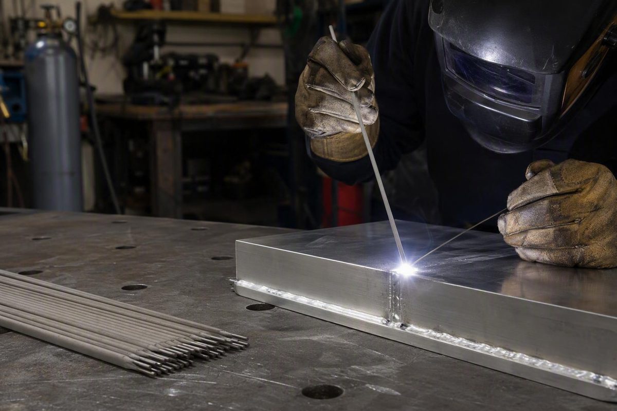
The short answer: aluminum SMAW works, but it is a niche process
Yes, aluminum can be welded by shielded metal arc welding, or SMAW, with a consumable flux-coated aluminum electrode. The electrode carries the arc and supplies filler metal, while its coating provides flux protection. Unlike MIG and TIG, aluminum SMAW does not require an external shielding-gas cylinder.
That can make aluminum stick welding useful for occasional maintenance, remote field work, some casting repairs, and relatively thick parts when AC TIG or spool-gun MIG equipment is unavailable. General aluminum-welding guidance nevertheless treats SMAW as an available but secondary process compared with TIG and MIG in this aluminum-welding overview.
Expect significant tradeoffs:
- Starts and restarts can be difficult.
- Electrodes burn rapidly.
- Flux and arc action can obscure the puddle.
- Spatter and heavy slag are common.
- Residue removal can take substantial time.
- Heat can accumulate quickly, causing distortion or sudden burn-through.
- Beads may remain rough even when the arc is maintained.
- Porosity, slag inclusions, incomplete fusion, cracking, and end craters are possible.
AC TIG is generally preferable when appearance, precise heat control, or thin material matters. Spool-gun MIG is normally more practical for faster deposition and repeated fabrication. Both processes require shielding gas, but they avoid several of the visibility, slag, and electrode-handling problems associated with flux-coated aluminum stick rods.
Approximately 1/8 inch is commonly presented as a practical lower boundary for aluminum SMAW, not an absolute physical limit. Commercial guidance discourages the process below that thickness because heat and puddle control become increasingly difficult in this aluminum stick-welding guide. Depositing metal on a thinner coupon does not make SMAW a repeatable or responsible choice for a thin repair.
Making a continuous bead also does not prove weld integrity. A personal E4043 project produced porosity near one start and mixed results in informal bend specimens; its author also acknowledged limitations in the test geometry and conditions in the documented project.
Scope and evidence limitation: This is cautious selection and coupon-testing guidance, not a qualified welding procedure. The available product pages omit important operating and engineering information, including manufacturer amperage ranges, authoritative compatibility tables, storage and reconditioning procedures, residue-removal instructions, mechanical properties, and certification details. Do not use this article by itself to authorize a structural, transportation, pressure-containing, lifting, or other safety-critical repair.
What E4043 aluminum stick rods are—and what the designation does not prove
E4043, or retailer-labeled 4043, is the aluminum stick-electrode designation most consistently represented in the documented products and practical reports reviewed here. It should not be confused with every other consumable containing 4043 aluminum.
For SMAW, look for a flux-coated consumable electrode explicitly labeled for stick or shielded metal arc welding. That is different from:
- Bare 4043 TIG filler rod, which is manually added to a gas-shielded TIG puddle
- Spool or bulk 4043 MIG wire, which is continuously fed through a welding gun
- Aluminum brazing rod, which is used without melting the base metal as a fusion weld does
- Generic torch repair rods not designed to sustain an electric arc
One Forney E4043 product is marketed for DC arc welding and as a torch-brazing alloy. That is a product-specific secondary use. It does not make ordinary brazing rods and flux-coated SMAW electrodes interchangeable. A shared filler designation does not establish the same coating, heat source, operating technique, joint design, or acceptance criteria.
E4043 being common also does not establish that a particular electrode is suitable for every aluminum alloy, casting, temper, joint, or service environment.
Use this selection sequence:
- Identify the base metal. Check drawings, material records, markings, or reliable documentation. Appearance alone is not alloy identification.
- Obtain the exact electrode package and manufacturer datasheet. A retailer category or search-result title is not enough.
- Confirm compatible base materials. Match the documented alloy, product form, and application to the actual part.
- Verify current type, polarity, and diameter-specific amperage. Products carrying the same 4043 label can still have different instructions.
- Check position, storage, residue-removal, and reconditioning requirements.
- Reject guesswork for consequential work. If the alloy or required performance is unknown, stop until those facts are established.
Treat phrases such as “highest strength,” “stable arc,” “minimal spatter,” or “low fuming” as seller or manufacturer marketing unless accompanied by applicable test data. They should not be converted into general guarantees.
The documented retail pages commonly omit one or more of the following:
- Detailed electrode chemistry
- Deposited-metal mechanical properties
- Electrode length
- Authoritative alloy-compatibility tables
- Position qualifications
- Classification or conformance documentation
- Storage and permitted reconditioning procedures
- Detailed flux-residue instructions
- Diameter-specific amperage ranges
Those omissions are more important than ratings, promotional language, or the number of rods in a package.
Comparing the documented E4043 rod options
The three documented offerings differ primarily in diameter, package quantity, format, and the precision with which they state polarity.
The prices below are undated snapshots from the supplied listing evidence, not current quotes or availability guarantees. Because the evidence did not include a capture date, verify every listing immediately before purchase. The inconsistent package information also prevents a meaningful cost-per-pound or cost-per-deposited-weld comparison.
| Seller or product | Classification as listed | Diameter | Package format | Stated current or polarity | Captured listed price | Major missing specifications |
|---|---|---|---|---|---|---|
| Forney item 45889 | E4043 | 1/8 in | 1/2 lb package | DC reverse polarity | $33.99 | Amperage range, electrode length, detailed alloy table, mechanical properties, certification, storage and residue instructions |
| INWELD 4043 retailer listing | 4043 | 3/32 or 1/8 in | 5 lb can | DC SMAW; exact polarity not supplied | $155.99 for 3/32 in; $149.99 for 1/8 in | Exact polarity, amperage, electrode length, alloy table, mechanical properties and certification |
| Hobart 4043 retailer listing | 4043 | 1/8 in | 10 electrodes | DCEP only, as stated by retailer | $12.50 | Package weight, amperage range, electrode length, alloy table, mechanical properties and certification details |
The Hobart pack has the lowest captured package price, but that does not establish the lowest cost per pound or per completed weld. Its package weight is not supplied, so it cannot be directly compared with the half-pound Forney package or five-pound INWELD can.
Actual usable-weld cost also depends on:
- Failed starts and restarts
- Electrode burn-off and stub loss
- Rods opened but not used
- Storage losses caused by deteriorated flux
- Coupons consumed while establishing settings
- Time spent removing residue
- Repairs rejected because of visible or internal defects
A small pack is the more cautious purchase for checking machine compatibility, practicing on matching scrap, or attempting one noncritical repair. A five-pound can becomes more rational only when repeated work justifies the inventory and the exact electrode has already proved suitable on representative material.
Bulk purchasing can work against an infrequent user. Practical reports describe aluminum electrode flux absorbing moisture during storage and becoming difficult to run. That is not permission to bake or improvise a drying procedure. It is a reason to buy realistic quantities and follow the exact manufacturer’s storage instructions.
Retailer ratings may provide context about packaging, delivery, or individual user experience. They do not prove fusion, mechanical properties, internal soundness, code compliance, or superiority over another electrode. Likewise, wording embedded in a URL is not manufacturing documentation; the available INWELD description does not substantiate a country-of-origin claim.
Before buying, obtain or confirm:
- Exact manufacturer datasheet
- Electrode classification, diameter, and length
- Required current type and polarity
- Diameter-specific amperage range
- Approved base materials
- Permitted welding positions
- Storage conditions
- Any authorized moisture-reconditioning method
- Flux-residue removal instructions
- Applicable classifications or certifications
If the seller cannot provide the information needed for the repair, the package price should not drive the decision.
Machine compatibility, polarity, and defensible starting amperage
Begin with the power source, not the amperage knob.
Compatibility decision path
-
Is the welder AC-only? Do not assume compatibility. The documented commercial products are described for DC operation, and the Forney and Hobart listings specifically state reverse polarity or DCEP.
-
Does the machine provide constant-current DC stick output? If not, stop and consult the equipment and electrode manufacturers.
-
Can the required polarity be selected?
-
Does the available output overlap the electrode’s documented amperage range?
-
Are the holder, leads, connectors, and work-return connection sound? An unstable welding circuit can resemble a bad electrode or unsuitable current setting.
-
Can the setup be tested on representative, noncritical coupons? If not, the repair itself should not become the experiment.
In this context, DCEP, electrode positive, DC reverse polarity, and DCRP describe the same electrical arrangement. DCEP is the most consistently documented polarity for the Forney and Hobart products and for the practical E4043 examples reviewed here.
It is not a universal rule for every possible aluminum electrode. The exact package or manufacturer datasheet overrides generic charts, commercial articles, forum settings, and this guide.
What amperage range is defensible?
There is no single verified setting for every 1/8-inch E4043 electrode. The available evidence instead provides several product-specific or secondary-source ranges:
- A forum author reported a 70–120 A DC-positive recommendation for the 1/8-inch Hobart 4043 electrodes used in that test in the WeldingWeb test record.
- A Weld.com demonstration described its 1/8-inch test rods as labeled for 75–130 A and DCEP in the polarity and preheat demonstration.
- A commercial guide gives approximately 80–135 A for a referenced 1/8-inch E4043 rod while warning readers to follow the electrode manufacturer’s specifications in YesWelder’s SMAW guide.
Together, those sources create a broad 70–135 A evidence envelope, but they do not create a universal operating range. The figures come from different products and evidence tiers, including a personal forum experiment, an informal demonstration, and a commercial article.
In the Hobart forum test, the operator had difficulty sustaining the arc at 80 A, preferred approximately 100–110 A on the tested equipment, and burned holes in 1/8-inch coupons when travel became too slow at 110 A. Another personal E4043 project reported using 1/8-inch electrodes at approximately 110–120 A. These are machine- and joint-specific observations, not settings to copy blindly.
A defensible setup method is:
- Read the exact electrode’s documented range.
- Begin inside that range.
- Test on matching coupons.
- Change one variable at a time.
- Stop if repeatable control and acceptable test results cannot be achieved within the permitted range.
Amperage alone cannot predict the result. Relevant variables include:
- Electrode diameter and coating condition
- Base-metal alloy, temper, and thickness
- Butt, fillet, groove, or casting-repair geometry
- Fit-up and root opening
- Arc length
- Travel speed
- Welding position
- Workpiece temperature
- Machine output and arc characteristics
- Hot-start or arc-force behavior
- Heat accumulated from previous beads
The Weld.com polarity comparison illustrates why the label controls. For the DCEP-labeled rod in that demonstration, DCEP with workpiece preheat produced the most consistent etched cross section among the tested samples. DCEN reportedly penetrated more but behaved poorly, while AC also produced poor results. Because the experiment used one product, one machine, and coupons of unidentified alloy, it does not establish a universal polarity ranking.
The practical conclusion is straightforward: verify constant-current DC capability, use the exact electrode’s specified polarity, and establish settings on representative coupons before touching the repair.
Preparation, electrode condition, and safety before striking an arc
Aluminum SMAW does not compensate for paint, grease, water, or heavy oxide. Preparation should be systematic and performed immediately before welding where practical.
Preparation order
-
Identify the material. Establish the alloy and temper where possible. Determine whether the part is cast, wrought, extruded, previously repaired, or contaminated by service.
-
Remove coatings, oil, and moisture. Use a cleaning product suitable for aluminum and follow its label and safety data. Do not assume one cleaner is appropriate for every contaminant or workplace.
-
Mechanically remove oxide. Use a stainless-steel brush reserved exclusively for aluminum. A brush previously used on carbon steel can cross-contaminate the surface.
-
Clean the joint faces. Oxide or contamination left in a root face, crack, groove, or inaccessible corner can become trapped in the deposit.
-
Establish close, consistent fit-up. Do not expect a fast-burning electrode to bridge irregular openings cleanly.
-
Prepare the work-return connection. Attach it to clean, sound metal as directed by the equipment manual. Inspect the holder, leads, connectors, and clamp.
-
Weld promptly. Aluminum oxide reforms after cleaning, so avoid leaving the prepared joint exposed while unrelated work is completed.
Cleaning matters because the oxide layer and underlying aluminum respond very differently to heat. Secondary guidance places the melting temperature of aluminum oxide near 3,700°F, compared with approximately 1,200°F for pure aluminum in the cited commercial guide. These are approximate explanatory figures, not an alloy-specific procedure specification.
Aluminum also transfers heat rapidly through the work. A joint may begin under apparent control and then become broad, fluid, distorted, or perforated as heat accumulates.
Electrode condition
Flux-coated aluminum electrodes may absorb moisture and become difficult to start or run consistently. Keep them sealed and stored according to the exact product instructions. For occasional work, buying fewer rods may be more economical than storing an opened bulk can for years.
Steel-electrode rebaking practices cannot automatically be transferred to aluminum flux coatings. The same restriction applies to deliberately preheating the electrode.
Workpiece preheat
Treat workpiece preheat as conditional, not mandatory. In one limited demonstration, preheating the work improved starting behavior and the observed cross section. In a separate forum experiment, a 300°F preheat produced an excessively broad bead that the operator found difficult to control in that operator’s test record.
These reports do not establish a safe or optimal universal temperature. Preheat that assists one combination of alloy, thickness, joint, machine, and electrode may create excessive heat in another. Do not specify preheat or interpass temperatures without the base alloy, temper, joint requirements, and applicable manufacturer or qualified-procedure guidance.
Safety baseline
Welding exposes unprotected people to hazardous electrical current, fumes, and ultraviolet radiation. Use appropriate PPE and ventilation, and follow the equipment manual and site rules over general article guidance as stated in Welder Facts’ safety terms.
When a cleaner is used, follow its label and safety data before bringing the part into a welding area. Do not treat a forum cleaning method or general-purpose solvent recommendation as universal.
Consult the electrode label and available safety documentation for storage, flux handling, ventilation, residue removal, and disposal. Do not assume that white or glassy aluminum-electrode residue can be handled exactly like slag from a familiar steel electrode.
A controlled workflow for running aluminum stick electrodes
The following workflow is limited to noncritical coupon trials. It is not a qualified welding procedure or authorization to repair an in-service component.
Step 1: Verify the complete setup
Read the electrode label and confirm:
- Classification and diameter
- Permitted base materials
- Required current type and polarity
- Manufacturer amperage range
- Position limitations
- Storage and cleanup instructions
Install the required polarity and inspect both welding leads. Confirm that the holder and work-return connection are sound. Set the current within the exact product’s stated range.
If the welder has adjustable hot start or arc force, do not assume a steel-electrode setting is appropriate. Unless the electrode or equipment documentation provides a setting, treat these controls as coupon-test variables and change only one at a time.
Step 2: Build representative coupons
Use cleaned practice pieces that match the repair’s known alloy, thickness, fit-up, and joint geometry as closely as practical. A flat bead on unrelated scrap says little about the behavior of a groove, fillet, crack excavation, or casting repair.
Prepare enough coupons to observe:
- Starting and restart behavior
- Travel speed
- Bead width
- Heat accumulation
- Slag removal
- Visible discontinuities
- Distortion
- Burn-through tendency
A single short bead does not establish repeatability.
Step 3: Establish the arc and shorten it immediately
Start the arc by the method permitted in the product instructions. Once established, settle into a very short arc. Practical reports describe keeping the coating nearly in contact with the work.
If the rod repeatedly extinguishes at a short arc, verify polarity, current, cleanliness, electrode condition, work connection, and machine behavior before simply increasing amperage.
Step 4: Travel quickly and minimize weaving
Aluminum stick electrodes burn rapidly, and the molten metal flows readily. Practical reports support faster travel than would be used with many ordinary steel electrodes, along with little or no weave.
One detailed E4043 project identifies fast travel, minimal weaving, difficult visibility, and substantial slag and spatter as defining process characteristics in the author’s project account.
Step 5: Monitor heat through indirect signs
Do not wait for a dramatic visual warning. Watch for:
- Bead width increasing
- Joint edges becoming difficult to distinguish
- Plate distortion
- Fit-up changing as tacks heat
- Changes in arc behavior
- Subsequent rods starting differently
- Burn-through developing near gaps, edges, or ends
If each successive bead becomes broader at unchanged settings, accumulated workpiece heat may be changing the result. Stop and revise the coupon sequence rather than assuming the amperage display is the only variable.
Step 6: Manage starts, restarts, and endings deliberately
Plan where the electrode will end before striking the arc. Rapid burn-off creates more stops and restarts than many operators expect.
Personal reports identify start porosity and end craters as recurring concerns. Clean the restart area by the product-authorized method and inspect the previous crater after removing residue. Do not strike randomly through old flux or adopt a universal crater-filling maneuver without electrode- and procedure-specific support.
Step 7: Remove residue and inspect the exposed deposit
Remove residue between passes and after welding by the method authorized for the electrode. A deposit cannot be meaningfully evaluated through opaque white or glassy material.
In one forum experiment, hot running water and a toothbrush reportedly removed hard white residue more effectively than impact tools. That is a personal observation involving one product, not a universal cleaning procedure.
After cleanup, inspect for:
- Surface porosity
- Crater cracks
- Incomplete tie-in
- Undercut
- Visible residue lines
- Excessive convexity
- Distortion
- Burn-through
- Cracks along the deposit or heat-affected area
An improved-looking bead proves only that its visible appearance improved. It does not establish internal fusion, mechanical performance, or suitability for service.
Step 8: Record and adjust
Record:
- Electrode product and diameter
- Polarity
- Amperage
- Welding machine
- Coupon alloy and thickness
- Joint geometry and fit-up
- Preparation method
- Workpiece temperature or preheat condition
- Travel behavior
- Visible results after cleanup
Change one variable at a time while remaining within product requirements.
For example:
- If the arc repeatedly dies, verify the circuit and arc length before adding current.
- If the bead becomes broad, examine travel and accumulated heat before assuming the initial current was wrong.
- If starts improve but the coupon burns through later, the initial setup may be workable while the sequence is not.
- If results differ between machines at the same displayed amperage, treat machine behavior as a variable.
Stop testing when a repeatable and acceptable result cannot be produced. Choosing another process can be the correct outcome of a coupon trial.
Troubleshooting hard starts, burn-through, porosity, and slag
The checks below are diagnostic possibilities, not proven causes. Several conditions can produce the same symptom, and more than one may be present.
| Symptom | What to check first | Coupon-test logic |
|---|---|---|
| Hard starting or repeated arc outages | Exact polarity, current against label, oxide removal, electrode condition, work connection, arc length and machine behavior | Correct setup and contamination issues before increasing amperage |
| Broad or uncontrollable bead | Excessive current, slow travel, long arc, accumulated heat, large gap or aggressive preheat | Change one variable; do not weave in an attempt to regain control |
| Burn-through | Slow travel, gaps, excessive current, overheated work, thin sections or edge geometry | Stop and reassess whether SMAW suits the material and joint |
| Rapid rod consumption | Normal fast burn-off, excessive current, long arc or unnecessary manipulation | Plan shorter segments, more restarts and sufficient coupon length |
| Poor puddle visibility | Long arc, heavy flux, wide weave or awkward access | Maintain a short arc and steady progression |
| Porosity | Oil, moisture, oxide, damp flux, long arc or contaminated starts and restarts | Reclean and reproduce the condition on coupons; do not assume one universal cause |
| Trapped residue | Inadequate cleaning, inaccessible joint, erratic heat input, poor travel or long arc | Expose and clean every pass using the product-authorized method |
| Incomplete fusion | Oxide, unstable heat, poor joint preparation, incorrect travel or wrong polarity | Verify every input; more penetration does not automatically mean adequate fusion |
| End crater or cracking | Abrupt termination, incompatible material combination, excessive restraint, heat input or unsuitable joint design | Stop and determine the cause instead of covering it cosmetically |
| Distortion | Excessive heat, long beads, unsuitable sequence, weak tack-up or thin material | Reconsider sequence and process choice |
| Difficult residue removal | Product-specific flux characteristics or an unsuitable removal method | Follow manufacturer instructions rather than assuming impact, washing or chemicals are universally permitted |
| Results vary between machines | Different output behavior, connections, controls or arc characteristics | Treat displayed amperage as only one variable |
Rapid electrode consumption is a recurring characteristic rather than automatic evidence of a defective package. It changes how the work must be planned. Use coupons large enough to evaluate multiple starts and stops, and expect more stub loss and restart zones than with many steel electrodes.
Porosity requires particular caution. Surface pinholes may be associated with contamination, moisture, arc length, or restart behavior, but appearance alone cannot identify a single cause.
The same limitation applies to residue inclusions and incomplete fusion. Removing visible slag is necessary, but it does not reveal everything inside the joint.
If cracking or significant distortion appears, stop. Reassess material compatibility, heat input, restraint, fit-up, joint design, and whether SMAW is appropriate. Do not bury a crack under additional filler as a cosmetic response.
Persistent inconsistency may also be machine-dependent. Informal users have described different starting and running behavior at similar displayed settings on different power sources. Forum discussions generally characterize aluminum electrodes as more demanding than ordinary steel rods and favor spool-gun MIG or AC TIG when those processes are available in this Miller forum discussion.
No troubleshooting table qualifies a weld. Visual inspection, retailer ratings, and forum photographs cannot establish internal soundness or mechanical performance.
When to put the stick rods down and choose MIG, TIG, or brazing
Process selection should follow the joint and required result, not merely the machine already in the shop.
| Process | Equipment needs | Portability and airflow sensitivity | Thin-material control | Deposition and productivity | Appearance and cleanup | Likely use case |
|---|---|---|---|---|---|---|
| Aluminum SMAW | Compatible constant-current power source and the correct flux-coated electrode; documented products generally require DC | Portable and no gas cylinder; useful where external gas is inconvenient | Generally poor relative to TIG; approximately 1/8 in is a common practical lower boundary | Rods burn rapidly, but stops, restarts and cleanup reduce effective productivity | Heavy slag, spatter, poor visibility and rough finish | Occasional non-cosmetic maintenance, remote work, some castings and thicker repairs |
| Spool-gun MIG | Compatible MIG power source, spool gun, aluminum wire and shielding gas | Gas shielding is airflow-sensitive; more equipment must reach the work | Better than SMAW but still setup-dependent | Generally fast and suitable for repeated work | No SMAW slag and more repeatable feeding | Production, repeated repairs, long seams and faster deposition |
| AC TIG | AC-capable TIG power source, torch, shielding gas, filler and suitable accessories | Gas shielding and equipment reduce field convenience | Generally the best of these fusion processes for precise puddle and heat control | Slower deposition than MIG | Strong bead-placement control and no SMAW slag | Thin material, visible joints and precise one-off fabrication |
| Torch brazing | Suitable torch, compatible filler and flux where required, with a joint designed for brazing | Portable, but heat and fire control remain important | Can suit some thin or specially designed joints | Application-dependent | Flux cleanup may be required | Non-fusion joints specifically designed and accepted for brazing |
Aluminum SMAW is most attractive when all of the following are true:
- A compatible constant-current DC source is available.
- The exact electrode is documented as compatible with the known material.
- External shielding gas is impractical.
- The material and joint permit manageable heat control.
- The repair is non-cosmetic.
- Extensive residue removal and cleanup are acceptable.
- Coupon testing produces repeatable results.
- Acceptance is based on more than the ability to deposit a bead.
MIG is generally the stronger practical choice for faster and more repeatable deposition across multiple similar joints.
AC TIG is generally preferable when precise control over heat, filler addition, puddle placement, and appearance matters. That does not automatically guarantee a sound weld; material selection, preparation, procedure, equipment, and operator capability still matter.
Brazing remains a separate process. It does not melt and fuse the base metal in the same way as welding. A product advertised for both SMAW and torch brazing must be used according to the instructions for the selected process.
Switch away from SMAW when:
- Thin material makes burn-through difficult to control.
- The alloy or temper is unknown and the repair is consequential.
- A clean or cosmetic joint is required.
- Repeated production requires consistent cycle time.
- Porosity, trapped residue, cracking, or fusion problems persist on coupons.
- The joint cannot be prepared or accessed adequately.
- Product documentation does not establish compatibility.
- Weld integrity must be demonstrated rather than assumed.
The relevant distinction is not “Can this rod make a bead?” It is “Can this process produce a suitable, verified repair on this material and joint?”
Frequently asked questions
Can I use aluminum stick welding rods with an AC-only welder?
Do not assume so. The documented Forney, INWELD, and Hobart products are described for DC operation, with Forney and Hobart specifically stating reverse polarity or DCEP.
An AC-only transformer welder should therefore not be treated as compatible unless the exact electrode manufacturer expressly permits AC. A limited experiment produced poor results when AC was used with a rod labeled for DCEP, but that does not prove every possible aluminum electrode is incapable of AC operation. It reinforces the need to follow the selected product’s instructions and the welder manual.
What amperage should I use for a 1/8-inch E4043 electrode?
Use the diameter-specific range printed on the exact package or manufacturer datasheet. Do not substitute the broad ranges collected from other products.
Available examples differ substantially: one Hobart forum test reported a 70–120 A DC-positive package range, while a commercial guide gives approximately 80–135 A for its referenced 1/8-inch E4043 electrode in the commercial guidance cited earlier. That variation is why the exact label must control.
Begin inside the permitted range on matching coupons. Account for polarity, machine behavior, arc length, fit-up, travel speed, joint geometry, electrode condition, and accumulated heat.
Does E4043 work with every aluminum alloy or casting?
No. E4043 being common does not establish suitability for every wrought series, casting alloy, temper, joint, or service condition.
Identify the base material and consult the exact electrode manufacturer’s compatibility information. If the alloy is unknown and the repair has structural, pressure, transportation, lifting, or other safety consequences, do not select the filler by appearance or availability alone.
Should aluminum stick rods or the workpiece be preheated?
Workpiece preheat is conditional. One limited demonstration reported easier starting and a more consistent observed cross section with preheat, while another operator found that a relatively high workpiece preheat produced an excessively broad, difficult-to-control bead.
Do not derive a universal temperature from either experiment. Alloy, temper, thickness, joint geometry, heat accumulation, and manufacturer guidance all matter.
Do not preheat, bake, or oven-dry the electrode unless its manufacturer specifically authorizes the method and temperature. An informal test involving a warmed electrode is not a storage or reconditioning instruction.
Are aluminum stick welds suitable for structural repairs?
The ability to deposit E4043 does not establish structural suitability. Informal demonstrations have shown porosity, trapped residue, incomplete fusion, and mixed bend-test results under limited conditions. Visual appearance cannot rule out internal defects.
This article is not a structural repair procedure. Consequential work requires known base material, documented filler compatibility, an applicable qualified procedure, appropriate professional or engineering review where required, and inspection or testing suitable for the service.
Final go-or-no-go checklist
Proceed to noncritical coupon testing only when you can answer yes to the relevant setup questions:
- Is the aluminum alloy and temper known where necessary?
- Is the exact electrode documented as compatible?
- Does the machine provide constant-current DC output?
- Can the label-specified polarity be installed?
- Is the manufacturer’s diameter-specific amperage range available?
- Can representative coupons be made from matching material and joint geometry?
- Can coatings, oil, moisture, and oxide be removed immediately before welding?
- Can close, consistent fit-up be maintained?
- Are the electrode storage and residue-removal instructions available?
- Can the deposit be cleaned and evaluated after every pass?
- Can testing and inspection match the consequences of failure?
On coupons, begin within the manufacturer’s range, maintain a very short arc, travel relatively quickly, minimize weaving, monitor accumulated heat, and record every change.
If the alloy is unknown, the machine is AC-only, the material is too thin for reliable control, documentation is missing, defects persist, or the repair must carry consequential loads, stop treating E4043 as a shortcut. Move to an appropriate MIG or TIG process and obtain qualified oversight.