
How to Choose the Right Electrode for the Metal, Machine and Weld
E6010, E6011, E6013, E7018 and E7024 narrow the field, but they do not by themselves establish polarity, amperage, storage or joint suitability.
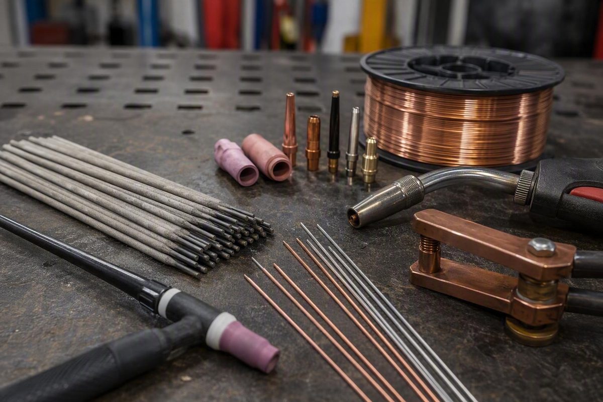
“Welding electrodes” can mean flux-coated stick rods, continuously fed wire, TIG tungsten, or resistance-welding tooling. Before comparing classifications, diameters, or prices, identify the welding process and exact base metal.
This guide focuses primarily on shielded metal arc welding (SMAW), commonly called stick welding. Familiar classifications such as E6010, E6011, E6013, E7018, and E7024 are useful screening tools, but they do not independently establish polarity, amperage, storage requirements, approvals, or suitability for a particular joint.
For controlled or critical work, follow the applicable welding procedure specification (WPS), governing code, project documents, equipment manual, and exact consumable data sheet. The generalized guidance below is introductory and should not be treated as a substitute for those authorities.
First identify what “welding electrode” means for your process
An electrode conducts welding current, but its form and role depend on the process.
In SMAW, the electrode is a consumable metal rod covered with flux. The metal core conducts current and supplies deposited weld metal. As the coating melts, it contributes shielding gas and protective slag. Coating formulations differ, so flux-coated rods can have substantially different arc, penetration, puddle, slag, current, and handling characteristics.
Other processes use the term differently:
- GMAW, or MIG welding: Uses a continuously fed consumable wire electrode. A machine with a wire feeder and gun requires compatible wire, not SMAW rods.
- FCAW, or flux-cored arc welding: Also uses a continuously fed wire electrode, but the wire contains a flux core.
- GTAW, or TIG welding: Uses a nonconsumable tungsten electrode to sustain the arc. Filler metal, when required, is generally added separately, so TIG tungsten and TIG filler rod are different products.
Resistance-welding catalogs may organize products by alloy class, taper, nose shape, weld-face dimensions, cooling-hole dimensions, offset, and holder fit. They also list tips, caps, holders, adapters, and dressing tools. For example, one specialist catalog includes straight and bent tips with 4RW and 5RW tapers alongside tip-dressing equipment, illustrating why “electrode” does not always mean “stick rod” (review the resistance-electrode categories).
Resistance-welding sidebar: Before ordering a replacement tip or cap, verify the specified alloy class, taper, geometry, face dimensions, cooling dimensions, offset where applicable, and holder compatibility. Do not select one from appearance or nominal diameter alone.
Retail categories create another source of confusion. Gouging electrodes, cutting rods, brazing rods, aluminum rods, cast-iron products, and related accessories may appear beside conventional SMAW electrodes. Forney’s category, for example, mixes several of these product types within a broad stick-related assortment (review the mixed stick-electrode catalog).
The rest of this guide addresses SMAW stick electrodes. If your equipment is designed for MIG, flux-cored, TIG, or resistance welding, do not apply the stick-electrode tables without first switching to process-specific guidance.
How a stick electrode works and what its classification tells you
A stick electrode has two principal functional parts:
- The metal core, which conducts current and supplies deposited metal.
- The flux coating, which helps stabilize the arc and contributes shielding and slag protection.
The coating also influences operating behavior. A fast-freezing electrode does not handle like one designed for a larger, more fluid puddle. Slag volume, manipulation, suitable current, and surface-preparation expectations can change by classification and exact formulation.
Reading E7018 as an example
A commercial classification guide summarizes E7018 this way:
- E identifies an arc-welding electrode.
- 70 indicates a minimum deposited-weld-metal tensile strength of 70 ksi within the classification system.
- 1 identifies all-position classification capability.
- 8 relates to coating and compatible current characteristics.
The same guide summarizes a position digit of 1 as all-position and 2 as flat and horizontal. Because the supplied evidence is commercial guidance rather than the governing classification standard, use it only to understand the general structure and verify the formal scope of every digit in the applicable authoritative classification reference (see the classification overview).
A classification’s tensile-strength digits do not establish the load capacity or suitability of the completed joint.
The final digit also cannot safely be reduced to a statement such as “all rods ending in 8 run the same.” Confirm the exact product’s approved polarity, operating range, coating characteristics, positions, and handling instructions.
Suffixes and extended designations matter as well. The supplied evidence is not sufficient to decode those requirements comprehensively, so verify the complete designation against an authoritative classification reference, manufacturer literature, and project documents.
Classification capability versus practical application guidance
Keep two different questions separate:
- What position capability does the formal classification indicate?
- What positions, currents, diameters, or applications does the manufacturer recommend for the exact product?
For example, E6013 contains a position digit of 1, but commercial application guidance may emphasize flat or horizontal work. That does not change the meaning of the classification digit; it means classification capability and practical product recommendations are not identical questions. The package, data sheet, WPS, and applicable classification standard should resolve the intended use.
Why similar classifications still require product-level verification
Products within the same broad family can differ in:
- Approved AC or DC operation
- Recommended amperage by diameter
- Position guidance
- Product approvals
- Packaging and moisture-control instructions
- Permitted exposure and reconditioning rules
- Arc starting, puddle, and slag behavior
Hobart’s catalog, for example, lists multiple E7018 and related low-hydrogen variants, including an E7018-1 H4R product described for AC or DC reverse-polarity operation. The catalog also contains position and approval filters, but those category-level filters do not prove that every product has every listed approval (review the manufacturer’s stick-electrode catalog).
A practical product-comparison worksheet should include:
| Field | Product A | Product B |
|---|---|---|
| Complete classification and suffix | ||
| Manufacturer and product name | ||
| Diameter | ||
| Approved polarity | ||
| Permitted positions | ||
| Amperage range for that diameter | ||
| Required approvals | ||
| Package and exposure instructions | ||
| Reconditioning or rejection rules | ||
| Agreement with the WPS |
This comparison is more useful than asking whether one brand or broad classification is universally “better.”
Label-reading checklist
Before placing an electrode in the holder, confirm:
- Complete classification, including suffixes
- Manufacturer and exact product name
- Electrode diameter
- Lot identification when required
- Package seal and coating condition
- Approved polarity
- Permitted welding positions
- Manufacturer’s amperage range for that diameter
- Storage, exposure, reconditioning, and rejection instructions
- Required project approvals
- Agreement with the applicable WPS
If the package, data sheet, and procedure appear to conflict, stop and obtain clarification from the manufacturer or the person responsible for the welding procedure.
E6010 vs. E6011 vs. E6013 vs. E7018 vs. E7024
This table is a screening aid, not a product specification.
| Classification | Generalized polarity | Penetration and puddle character | Surface condition | Common applications | Position limitations | Starting technique cue | Handling caution |
|---|---|---|---|---|---|---|---|
| E6010 | DCEP | Relatively deep penetration; fast-freezing puddle | More tolerant of imperfect surfaces than E6013, but cleaning remains necessary | Carbon-steel roots, pipe, construction, and tacking where permitted | Classification is commonly associated with all-position use | Whip-and-pause may be used when the procedure calls for it | Confirm that the power source can run the exact product |
| E6011 | AC or DCEP | Fast-freezing and relatively deep-penetrating | Often investigated for repair steel that cannot be prepared perfectly | Repairs, roots, general carbon-steel work, and AC-machine applications | Commonly associated with all-position use | Controlled manipulation or whipping may be used | AC capability does not make it an automatic E6010 substitute |
| E6013 | May include AC, DCEP, or DCEN | Softer arc; moderate or relatively shallow penetration | Better starting candidate for clean steel | Thin steel, light fabrication, and appearance-sensitive work | Formal classification and exact product guidance must both be checked | Straight drag or short arc is a common starting cue | Slag can obscure problems if placement, heat, or cleaning is inadequate |
| E7018 | Commonly DCEP; some products also support AC | Low-hydrogen family with a smoother, more fluid puddle than fast-freeze rods | Clean preparation is important | Structural and other strength-sensitive steel work | Commonly associated with all-position use; verify the product | Slight drag and a controlled short arc are common cues | Requires product-specific moisture control |
| E7024 | Product-specific | High-deposition, relatively fluid operation with substantial slag | Generally used on prepared steel | Production welding where high deposition is useful | Generally flat and horizontal rather than overhead | Steady drag according to product guidance | Position limits and fluid slag must be observed |
E6010
E6010 is generally associated with DCEP, relatively deep penetration, a fast-freezing puddle, and carbon-steel root, pipe, and construction applications. Its puddle may be manipulated to control root behavior, but the proper technique depends on the joint, procedure, and welder qualification.
E6011
E6011 occupies similar practical territory but is generally associated with AC as well as DCEP. That makes it a candidate for an AC-only machine when E6010 is not compatible with the available power source.
The two classifications should not be treated as procedurally interchangeable. A trade-publication comparison describes both as fast-freezing, relatively deep-penetrating, all-position electrodes while emphasizing that their flux compositions differ (read the E6010 and E6011 comparison).
If a qualified WPS specifies E6010, do not substitute E6011 without authorization.
E6010 and E6011 may tolerate imperfectly cleaned repair surfaces better than E6013, but that does not justify leaving paint, oil, moisture, heavy rust, or other avoidable contamination in the joint. Prepare sound metal as thoroughly as the work permits.
E6013
E6013 is generally associated with a softer arc and moderate or relatively shallow penetration. It is commonly investigated for clean, thinner steel and light fabrication where controllable heat and bead appearance are priorities.
A straight drag or short arc can be a useful starting cue, but it is not a complete procedure.
Check both the classification and exact manufacturer guidance for position and polarity. Do not infer operating characteristics from the classification alone.
E7018
E7018 is a low-hydrogen, 70 ksi-class family associated with structural and other strength-sensitive steel applications. The 70 ksi figure describes minimum deposited-weld-metal tensile strength within the classification system; it does not establish the strength of a completed joint.
The exact variant determines AC or DCEP compatibility, approvals, operating range, and handling requirements. For controlled work, “some 7018” is not an adequate purchasing specification. Confirm the full designation, manufacturer, product, diameter, approvals, and moisture-control documentation.
E7024
E7024 is generally associated with high deposition in flat and horizontal welding. Commercial guidance warns against overhead use because of its fluid slag system, so it should not be treated as an overhead electrode without exact product and procedural authorization.
High deposition is useful only when the joint, position, equipment, and procedure can accommodate the electrode.
Choose by base metal and the job the weld must perform
Start with the exact base-metal grade, not color, magnetism, surface finish, or a broad guess such as “steel.” If the material cannot be identified, pause before selecting filler metal—especially for critical repairs or procedure-controlled work.
Use this decision path:
- Identify the welding process.
- Identify both base metals from reliable documentation.
- Determine what the weld must do.
- Check the WPS, drawing, code, or customer specification.
- Narrow the consumable family by compatibility and required properties.
- Confirm position, polarity, diameter, machine output, approvals, and handling.
- Verify the exact product data sheet before purchase.
Application matrix
| Work or base metal | Electrode family to investigate | Questions to resolve |
|---|---|---|
| Clean, thin carbon steel | Smaller E6013 or another procedure-approved option | How much penetration is required? Is burn-through a concern? What does the exact product permit? |
| Imperfectly cleaned repair steel | E6011, or E6010 when suitable and permitted | Can the metal be identified and cleaned further? Is the repair critical? Can the machine run the product? |
| Carbon-steel pipe or root work | Often E6010; sometimes E6011 where permitted | What does the WPS specify? What joint geometry and technique are required? |
| Structural low-hydrogen work | Specified E7018 variant or another approved low-hydrogen classification | Which full designation, approvals, polarity, and handling controls apply? |
| Flat, high-deposition work | E7024 candidate | Is the joint flat or horizontal? Can the machine provide the required output? |
| Stainless steel | 308-, 309-, 316-series, or another matched product | What are the exact base alloys and service requirements? |
| Cast iron | Nickel-based products such as Nickel 99 or E Ni-CI may be candidates | What type of cast iron is present, and what approved repair plan applies? |
| Aluminum | E4043 or another aluminum SMAW product may be available | Is SMAW suitable, and what does the exact product documentation require? |
| Wear surface | Application-specific hardfacing electrode | What substrate, service conditions, and approved buildup system apply? |
Carbon steel
E6010, E6011, E6013, and E7018 are common candidate families for carbon steel, but they address different operating needs. Narrow the choice by joint requirements, position, surface condition, machine polarity, required properties, and procedure.
For example:
- A pipe root on a compatible DC power source may point toward E6010 if the WPS permits it.
- Repair work using an AC machine may point toward E6011.
- Thin, clean light fabrication may point toward a smaller E6013.
- Structural work requiring a low-hydrogen consumable may point toward a specified E7018 variant.
These are screening examples, not approvals.
Stainless steel
Retail catalogs include 308-, 309-, and 316-series stainless consumables, but those family names do not replace base-alloy identification. The exact selection must account for the documented materials, service requirements, and applicable procedure.
Do not select stainless filler merely because a workpiece appears corrosion-resistant or is nonmagnetic.
Cast iron
Commercial catalogs list nickel-based products such as Nickel 99 and E Ni-CI. Those listings establish that such products exist, not that one is suitable for every cast-iron repair.
Identify the material and use the exact manufacturer’s instructions or an approved repair procedure rather than building a method from a retailer category description.
Aluminum
E4043 and other aluminum SMAW electrodes are commercially available. Availability alone does not establish suitable settings, preparation, machine compatibility, or whether SMAW is preferable to another process for the component.
Confirm the exact alloy and product instructions before proceeding.
Hardfacing
Hardfacing deposits harder material over a softer substrate. Retail examples include products intended for ground-engaging equipment, but one product should not be assumed suitable for every wear application.
A broad retailer assortment demonstrates the market range from carbon-steel electrodes to stainless, nickel, aluminum, and hardfacing products (view the material and classification assortment).
Low-alloy and higher-strength work
Low-alloy and higher-strength classifications are specialist consumables. Do not select them from tensile-strength digits alone. Base-metal compatibility, required weld-metal properties, service conditions, approvals, and project documentation may all control the choice.
A catalog filter does not establish approval for every listed product.
Match electrode diameter and starting amperage to the work
Electrode diameter affects:
- Usable amperage
- Heat input and burn-through risk
- Puddle size and control
- Bead width
- Deposition rate
- Access to narrow joints and root openings
- Practicality in vertical and overhead positions
Smaller electrodes generally offer more control on thin material and constrained joints. Larger electrodes generally require more current and can support greater deposition on thicker work.
Diameter cannot be selected from material thickness alone. Joint type, groove geometry, root opening, fit-up, position, classification, pass function, machine output, and the WPS also matter.
Generalized SMAW starting-amperage chart
These values are nonauthoritative starting guidance from a commercial settings chart. They are not manufacturer specifications and do not guarantee an acceptable weld. Check the exact electrode data sheet, machine capability, position, and procedure, then test on representative scrap where permitted.
| Electrode | 3/32 in. | 1/8 in. | 5/32 in. |
|---|---|---|---|
| E6010 | 40–85 A | 75–125 A | 110–160 A |
| E6011 | 40–90 A | 75–125 A | 110–160 A |
| E6013 | 40–90 A | 90–130 A | 120–180 A |
| E7018 | 70–100 A | 90–140 A | 110–165 A |
ArcCaptain publishes these classification-and-diameter ranges as starting points and advises testing and adjusting for the actual machine, material, and position (review the source settings chart).
The table shows why diameter alone is insufficient. A 3/32-inch E6010 and a 3/32-inch E7018 do not have the same generalized range.
Vertical and overhead welding generally require tighter puddle control and may use less amperage than flat welding, subject to the manufacturer’s limits and the WPS. Reducing current too far can introduce other problems, so evaluate the entire setup rather than changing amperage in isolation.
The familiar “one amp per thousandth of electrode diameter” idea is only a rough mental reference. A 1/8-inch electrode is 0.125 inch in diameter, but the table shows different ranges around 125 A depending on classification. It must not override product-specific data.
A practical diameter-selection sequence
- Check whether the WPS specifies a diameter or maximum electrode size.
- Determine the pass function: root, fill, cap, or fillet.
- Consider material thickness and burn-through risk.
- Account for root opening, groove angle, access, and fit-up.
- Determine whether the position calls for a smaller, more controllable puddle.
- Confirm that the machine can supply the required output.
- Select a product and diameter permitted by its data sheet.
- Test the starting setting on representative scrap where allowed.
Do not buy the largest electrode the holder can accept simply to increase deposition. If the machine cannot maintain the required output or the joint cannot control the puddle, the larger diameter is not an efficient choice.
Verify polarity, machine capability, and technique before striking an arc
A package that appears compatible with the base metal may still be unsuitable for the power source.
Use this pre-weld sequence:
- Confirm the complete classification and exact product.
- Confirm the diameter.
- Read the manufacturer’s approved polarity.
- Check the amperage range for that diameter and position.
- Confirm the permitted welding positions.
- Check the machine’s output types and usable range.
- Review the equipment manual for consumable limitations.
- Confirm agreement with the WPS and project requirements.
- Inspect the package and electrode condition.
- Make a controlled test weld when permitted.
Use the following only as an initial guide:
| Classification | Generalized polarity guide |
|---|---|
| E6010 | DCEP |
| E6011 | AC or DCEP |
| E6013 | Potentially AC, DCEP, or DCEN |
| E7018 | Commonly DCEP; some variants support AC |
Nominal AC or DC output does not prove that a machine will run every electrode variant reliably. The supplied evidence does not establish a universal open-circuit-voltage threshold, so consult the equipment manual and exact consumable data sheet rather than guessing.
Basic setup
- Wear PPE suitable for the welding process and task.
- Provide appropriate ventilation and follow site controls.
- Inspect the holder, leads, work clamp, and connections.
- Attach the work clamp to clean, bare metal.
- Set the verified polarity.
- Choose a starting amperage within the exact product’s range.
- Test on representative scrap when permitted.
- Adjust one variable at a time while remaining within procedural limits.
Welding exposes unprotected people to current, fumes, heat, and ultraviolet radiation. Welder Facts states that its articles assume proper PPE and ventilation and that equipment manuals and site rules take precedence (review the safety and use notice).
Technique changes with electrode behavior. Whipping, dragging, arc length, work angle, travel angle, and travel speed are variables rather than universal commands. Generalized guidance associates whipping with E6010, a slight drag with E7018, and a straight drag or short arc with E6013. Apply those only as initial cues within the exact product and procedure guidance.
Troubleshoot sticking, burn-through, poor bead shape, and electrode damage
A symptom rarely proves a single cause. Use this table to organize checks, not to make a complete defect diagnosis.
| Symptom | What to check |
|---|---|
| Rod repeatedly sticks | Amperage may be too low; arc length may be collapsing; polarity may be wrong; work-lead contact may be poor; electrode may be damp or damaged; machine may not suit the product |
| Tall, ropey, or lumpy bead | Low current, inconsistent travel, excessively short arc, poor angle, wrong polarity, or unsuitable manipulation |
| Excessively flat bead | Excessive amperage or dwell, slow travel, oversized electrode, or a puddle that is too fluid for the position |
| Burn-through | Excessive current or dwell, electrode too large, thin material, excessive root opening, or problematic fit-up |
| Unstable start or erratic arc | Work-clamp contact, loose connections, dirty contact area, electrode condition, polarity, settings, or power-source compatibility |
| Porosity or inconsistent operation | Rusted core, cracked flux, contamination, suspected moisture exposure, surface preparation, or another process or technique problem |
| Slag trapped at bead edges or between passes | Incomplete cleaning, bead placement, travel or work angle, heat input, joint access, or unsuitable manipulation |
| Flux breaks away | Impact damage, deteriorated coating, poor storage, or an electrode that should be rejected under the manufacturer’s rules |
Repeated sticking may justify a small amperage increase when the exact product range permits it, but first verify polarity, connection quality, and electrode condition.
Burn-through does not always mean “turn the amps down.” Reducing current too far can create a different problem without correcting the fit-up.
For slag-related problems, ask:
- Was the previous pass cleaned fully?
- Could the electrode reach the required parts of the joint?
- Was the bead shape suitable for the next pass?
- Did the travel angle move slag ahead of the puddle?
- Was the selected heat input within the product range?
- Was the technique appropriate for that electrode?
Change one variable at a time on suitable scrap or a noncritical practice joint. Remain within the manufacturer’s operating range and document changes when the work is procedure-controlled.
Stop and escalate when you encounter cracks, repeated porosity, unknown base metal, damaged moisture-sensitive consumables, or any unresolved issue on a critical or qualified weld. Obtain direction from the responsible welding supervisor, inspector, engineer, or other authorized person.
Store electrodes correctly and buy by specification, not package price
All electrodes benefit from clean, dry storage and protection against coating damage. Low-hydrogen products such as E7018 require particular moisture control, but the supplied evidence does not support one universal storage, holding, or re-drying temperature. Follow the exact manufacturer’s requirements for sealed storage, atmospheric exposure, heated holding, reconditioning, and rejection (review the commercial storage overview).
Visible warning signs include:
- Rust on the exposed core
- Cracked, flaking, or missing flux
- Contamination on the coating
- Difficulty striking or maintaining an arc
- Porosity or inconsistent operation
If exposure history is unknown, apply the manufacturer’s acceptance or rejection rules.
Purchasing checklist
Before comparing sellers, record:
- Exact welding process
- Exact base-metal grade or grades
- WPS and project requirements
- Complete electrode classification and suffix
- Manufacturer and product name when specified
- Required diameter and length
- Approved polarity
- Permitted welding positions
- Amperage range for the selected diameter
- Required approvals and documentation
- Package condition and seal type
- Storage capacity at the shop or job site
- Seller’s unit of measure
- Package weight or rod count
- Lot traceability requirements
- Quantity required, including reasonable process waste
Retail catalogs commonly show classifications such as E6010, E6011, E6013, E7018, and E9018 in diameters including 3/32, 1/8, and 5/32 inch. Package formats range from small packs to larger cans, boxes, and cartons.
Listings may quote:
- Price per pound
- Mini pack
- Bulk can
- Master carton
- Rod count
- Three- or four-rod pack
- Pair of resistance electrodes
- Individual replacement tip
Normalize prices to the same relevant unit before comparing products. A low package price may reflect a small quantity. Conversely, a bulk carton may have a lower unit cost but create a storage or exposure problem if the shop cannot maintain the required conditions.
Also inspect what a category count includes. Retail pages may mix filler electrodes with gouging products, cutting rods, brazing rods, storage accessories, and resistance-welding tooling. Catalog totals do not prove that every listing is an SMAW filler electrode, and approval filters do not establish approvals for every product.
Do not rank products from package design, price, seller prominence, or review count. The supplied evidence does not independently compare arc quality, deposited-metal strength, slag release, moisture resistance, durability, or service life.
Frequently asked questions
What is the difference between a welding electrode and a welding rod?
“Electrode” is the broader term. It can refer to an SMAW stick electrode, MIG or flux-cored wire, TIG tungsten, or resistance-welding tooling.
In stick welding, “welding rod” and “stick electrode” are often used interchangeably because the flux-coated rod both carries current and supplies filler metal. In TIG welding, the tungsten electrode and separate filler rod have different functions. A resistance-welding electrode is conductive tooling rather than a flux-coated filler rod.
Identify the welding process before ordering anything labeled simply as an electrode or rod.
Should I use E6010, E6011, E6013, or E7018?
Use the base metal, joint, position, power source, required properties, surface condition, and WPS to narrow the choice:
- E6010: Investigate for carbon-steel roots, pipe, and relatively deep-penetrating fast-freeze work when DCEP is available and the procedure permits it.
- E6011: Investigate for similar fast-freeze work when AC compatibility is needed or repair surfaces cannot be prepared perfectly.
- E6013: Investigate for clean, thinner steel and light fabrication where a softer arc and moderate or relatively shallow penetration are appropriate.
- E7018: Investigate when the job specifies a low-hydrogen, 70 ksi-class consumable for structural or other strength-sensitive steel work.
None is universally best. E6011 must not replace E6010 in a qualified procedure without authorization, and an E7018 product should not be purchased until its full designation, polarity, approvals, and handling rules have been checked.
What size welding electrode should I use for 1/4-inch steel?
A 1/8- or 5/32-inch electrode may be a candidate for some 1/4-inch steel joints, but thickness alone cannot determine the correct size. A fabrication guide gives those diameters as general possibilities while noting that electrode type and available amperage also matter (see the general rod-size guidance).
A root pass, vertical groove, flat fillet, and high-deposition fill pass may require different diameters on the same plate thickness. Check the joint design, position, fit-up, classification, machine output, product range, and WPS.
Can E7018 welding electrodes run on AC?
Some can, but AC capability must not be assumed for every E7018 product or every AC machine.
Check the complete product designation and manufacturer’s data sheet, then verify the equipment manual. Nominal AC output alone does not prove compatibility with the exact electrode.
How should low-hydrogen electrodes be stored?
Store them under the moisture-control conditions specified by the exact consumable manufacturer and applicable WPS. Instructions may address sealed storage, permitted exposure after opening, heated holding, reconditioning, and rejection.
Do not apply a universal oven temperature or exposure time. If the package is damaged, the exposure history is unknown, or the flux is cracked or contaminated, follow the manufacturer’s disposition rules or escalate the decision. A visually sound electrode is not necessarily within its approved moisture condition.
The final selection sequence is straightforward:
- Identify the welding process and exact base metal.
- Check the WPS, drawing, code, and job requirements.
- Narrow the electrode classification.
- Confirm position and polarity.
- Choose a diameter the joint and machine can support.
- Verify the exact product data sheet and required approvals.
- Inspect and store the electrodes as the manufacturer directs.
- Test generalized starting settings on suitable scrap when permitted.
Classification numbers organize the decision; they do not complete it. For the actual weld, follow the authority hierarchy: WPS or governing code where applicable, site rules, equipment manual, exact consumable data sheet, and only then generalized educational guidance.