
Choose a Welder Extension Cord by Input Power—not Welding Amps
Choose a welder extension cord by input current, voltage, length, plug and cord-set rating. Diagnose voltage drop without overlooking unsafe connections.
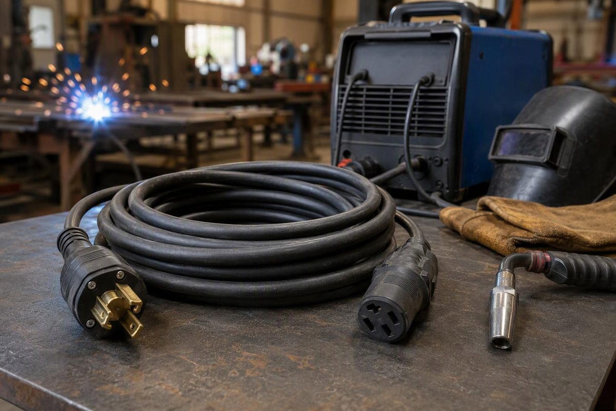
Use an extension cord only when your welder’s manual permits it, and choose it from the input-power requirements—not the welding amperage on the front panel. The cord must also have the right connectors, an equipment grounding conductor and a rating suitable for the load and work environment.
There is no single “welder gauge” that covers every 120 V MIG machine, dual-voltage inverter and 240 V stick welder.
Start with the manual, then check the cord label
Before buying, record these details:
| Check | What you need to establish |
|---|---|
| Welder identity | Exact model and the manual applicable to its serial number |
| Input power | Supply voltage, phase and input-current requirements |
| Extension-cord instructions | Minimum conductor size, maximum length and any restrictions |
| Connections | Welder plug, supply receptacle and required grounding arrangement |
| Cord-set rating | Voltage, current, conductor size and permitted environment |
The distinction between input and output current matters. The extension cord supplies the power-conversion equipment; it does not carry the same current as the electrode or work lead. For example, Miller’s April 2026 Multimatic 215 PRO manual lists a rated maximum supply current of 28.9 A at 240 V and a separate effective supply current of 14.6 A. Its extension-cord table specifies heavy-duty, three-conductor cord, minimum 12 AWG, maximum 50 ft (15 m), with an equipment grounding conductor. Those are model-specific instructions, not a rule for every welder, and the extension table does not replace electrical-service checks for the entire supply run. Miller Multimatic 215 PRO manual, §§4-4–4-5
Do not select a cord simply by taking the lower effective-current figure from the nameplate. Likewise, do not copy a fixed-wiring conductor size from the electrical-service table—or an output welding-cable size from the welding-lead chart. These serve different purposes. If the extension instructions are missing or unclear, ask the manufacturer or a qualified electrician to resolve the selection.
Choosing gauge and length for 120 V or 240 V
Lower AWG numbers mean larger conductors: 10 AWG is larger than 12 AWG; 8 AWG is larger again. But conductor size alone does not establish the rating of the complete cord. Its plugs, receptacle connector and construction also matter. Southwire’s catalog, for example, includes 12/3 cord sets rated 15 A and 8/3 welding cord sets with 6-50 connectors rated 40 A. Read the actual cord-set rating rather than assuming a gauge or connector guarantees a particular capacity. Southwire cord catalog
For a 120 V welder, check both the extension requirements and the branch circuit. A heavier extension cannot turn an inadequate circuit into an adequate supply. The Multimatic 215 PRO, for instance, specifies a 15 or 20 A individual branch circuit for its 120 V connection. Miller manual, §4-6
For a 240 V welder, match the actual plug configuration rather than shopping for a generic “three-prong” cord. The same Miller manual specifies a NEMA 6-50 receptacle and shows two input lines plus an equipment grounding conductor. An adapter that fits mechanically does not establish that the supply voltage, grounding or circuit protection is correct. Never remove a grounding pin or improvise a grounding connection. Miller manual, §4-7; CCOHS electrical-safety guidance
Choose the shortest single cord that reaches safely. More length adds conductor resistance; under load, that resistance produces voltage drop and heat. Larger conductors reduce resistance, but cannot repair a loose receptacle or undersized upstream wiring. Voltage-drop assessment depends on conductor size, circuit distance and current—not length alone. Southwire voltage-drop guidance
If you need 100 ft and the manual only specifies an extension up to 50 ft, do not extrapolate a gauge by guesswork. Get an approved arrangement or move the supply closer.
If the welder performs worse on the extension
Low supply voltage is worth checking when output falls after adding a cord. Hobart’s August 2004 Handler 140/180 troubleshooting table identifies low line voltage as a possible cause of low weld output. It does not establish that every unstable arc comes from the extension. Hobart manual, §7-8
Use this sequence before compensating with higher welding settings:
- Stop for electrical warning signs. Unusual heat, burning odor, discoloration or damaged insulation calls for taking the connection out of service—not another test weld. CCOHS warns that unusually warm or hot outlets or cords can indicate unsafe wiring conditions. CCOHS guidance
- Switch off and disconnect power before inspection. Check both cord ends, pins, jacket and connector fit; verify the cord against the manual.
- Compare without the extension, if the welder can safely reach the correct receptacle and there are no unresolved electrical warning signs. Keep material, consumable and welding settings unchanged. Improvement points toward the supply path, but does not identify the faulty component by itself.
- Have a qualified person check voltage under load if the problem persists. Do not open panels or probe live receptacles yourself.
- Check the welding circuit separately. Poor work contact, loose output connections and wire-feed problems can imitate a power problem; see how the welding return path works.
For U.S. workplaces covered by OSHA’s general-industry electrical rules, electrical testing is restricted to qualified persons. The rules also prohibit repeatedly resetting a protective device without determining that the circuit can be safely energized. OSHA §1910.334
Route and use it safely
Inspect the cord before use, lay it out rather than leaving it rolled up, and keep it clear of hot metal, spatter, sharp edges and vehicle traffic. Protect pinch points and crossings. Use a cord suitable for outdoor exposure when required, but do not treat an outdoor jacket as permission to leave connections in water. Buy equipment with certification markings accepted in your jurisdiction, and retain required GFCI protection. CCOHS electrical-safety guidance
For U.S. construction work, OSHA specifies three-wire, hard- or extra-hard-usage extension cord sets for portable tools and appliances. Site rules may impose additional requirements. OSHA §1926.405
Treat the extension as temporary reach, not permanent shop wiring. If it is part of every welding setup, a correctly installed receptacle near the work area is the better problem to solve.