
Size Welding Leads by Amperage, Duty Cycle and Total Circuit Length
Choose welding lead cable by amperage, duty cycle and combined length, then diagnose hot connectors, voltage drop, damaged insulation and weak work paths.
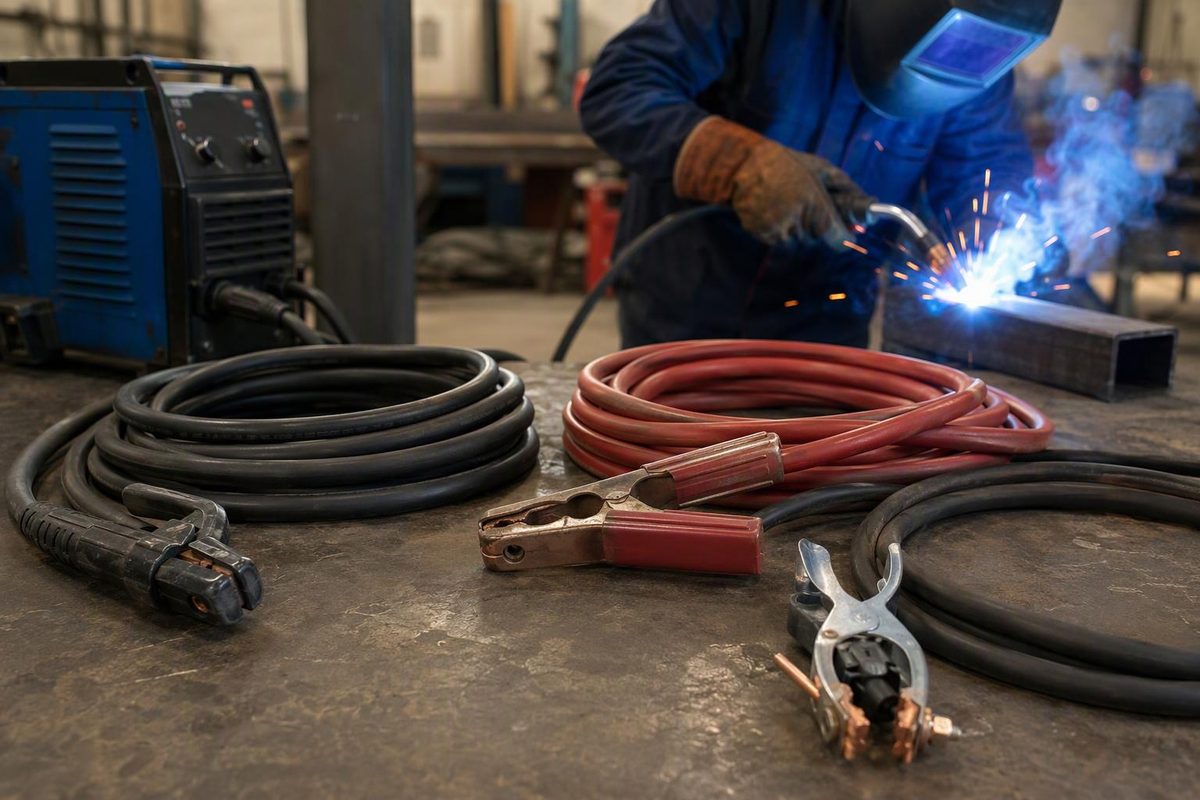
Welding leads are the flexible cables that carry output current between an arc-welding power source and the arc. In a typical stick setup, one lead runs to the electrode holder and the other to the work clamp. On a wire welder, the gun assembly carries the electrode-side current, while a separate work lead completes the circuit.
Lead size cannot be selected from amperage alone. Use the welder manufacturer’s table for the intended amperage, duty cycle and combined circuit length. Cable condition, connectors, lugs, holder and work clamp matter too: one loose or contaminated connection can create more trouble than an otherwise adequate cable.
“Work lead” is more accurate than “ground lead”
The work lead carries welding current back to the power source. It is not the same as the protective equipment-grounding conductor on the welder’s input circuit. The workpiece may separately require grounding, but that does not replace the work connection.
This distinction helps with troubleshooting. The current path includes the electrode cable or gun, electrode or wire, arc, workpiece, work clamp, work cable and both output-terminal connections. A good clamp attached to an electrically isolated component still leaves an incomplete path; see how the complete welding circuit affects the arc.
Choose cable gauge from four inputs
1. Maximum welding amperage
Size for the highest output the lead will actually carry, not the average current over a job. Accessories must keep up as well: the holder, clamp, connectors and lugs need suitable current capacity.
2. Duty cycle at that amperage
Duty cycle is the permitted arc-on time within a stated test period, commonly 10 minutes. A cable carrying high current continuously accumulates more heat than one used for short welds with cooling intervals.
OSHA’s construction rule requires completely insulated, flexible arc-welding cable capable of handling the work’s maximum current while accounting for duty cycle. It also requires the return cable to have capacity equal to or greater than the welding unit’s specified maximum output; a shared return must handle the combined maximum outputs of the machines it serves (29 CFR 1926.351). Site rules and the equipment manual may be more restrictive.
3. Combined length of both sides of the circuit
Add the electrode-side and work-side lengths:
Total weld-circuit length = electrode lead length + work lead length
A machine 50 ft from the joint with a 50 ft electrode lead and 50 ft work lead has a 100 ft circuit—not a 50 ft circuit. If one side is 75 ft and the other is 25 ft, the total is still 100 ft.
Longer cable has more resistance. Under load, that resistance causes voltage drop and heating. The practical result can be less voltage available at the arc, changed arc behavior and hot cable or connections. Increasing conductor area reduces resistance, which is why longer runs generally require a larger conductor.
4. The exact machine and application
Use the current manual’s cable table where available. Do not treat a generic online ampacity chart as authority for every machine, cable construction or environment.
The following excerpt illustrates how strongly current, length and duty cycle affect selection. It comes from a Millermatic 252 manual and applies to copper cable under that table’s assumptions; it is not a universal replacement for another welder’s manual (Miller Millermatic 252 owner’s manual, Section 5-2).
| Welding current | Up to 100 ft total, 10–60% duty | Up to 100 ft total, 60–100% duty | Up to 150 ft total | Up to 200 ft total |
|---|---|---|---|---|
| 100 A | 4 AWG | 4 AWG | 4 AWG | 3 AWG |
| 150 A | 3 AWG | 3 AWG | 2 AWG | 1 AWG |
| 200 A | 3 AWG | 2 AWG | 1 AWG | 1/0 AWG |
| 250 A | 2 AWG | 1 AWG | 1/0 AWG | 2/0 AWG |
| 300 A | 1 AWG | 1/0 AWG | 2/0 AWG | 3/0 AWG |
In AWG notation, a smaller number means a larger conductor; after 1 AWG come 1/0, 2/0, 3/0 and 4/0 in increasing size. The Miller table states that its sizes are based on no more than a 4 V drop or at least 300 circular mils per ampere. It also says to move to the next larger size if the cable overheats.
Lincoln Electric gives the same selection logic: use rated output, duty cycle and the combined electrode-plus-work cable length. Its worked example selects 2/0 cable for 400 A at 60% duty cycle with 100 ft total cable, while noting that longer lengths are upsized mainly to limit cable voltage drop (Lincoln Electric’s cable-selection guide). That example is useful for understanding the method, not for overriding a model-specific table.
What to check when leads run hot or the arc changes
De-energize the equipment and follow its shutdown instructions before opening, disconnecting or servicing the output circuit. Then work through the path in order:
- Confirm the setup. Check polarity, welding current, duty cycle and total circuit length against the current machine manual. Make sure an added extension did not push the circuit into a larger-cable column.
- Inspect the full cable. Look for cuts, crushed sections, hardened insulation, exposed strands, burn damage and repairs. Check areas near the holder, clamp and connectors especially closely.
- Inspect every termination. A loose lug, dirty terminal face, undersized connector or poor crimp concentrates resistance at one point. Miller warns that an improper output-cable connection can generate excessive heat, start a fire or damage the machine; its instructions require clean mating surfaces and a tight lug-to-terminal connection (Millermatic 252 manual).
- Check the holder and clamp. Weak spring pressure, burned jaws, loose internal connections or attachment over paint, scale or rust can restrict current. Put the work connection on clean metal as near the weld as practical unless the approved procedure or equipment instructions require otherwise.
- Look for a localized hot spot. A connector that heats much faster than the cable points toward contact resistance. Uniform cable heating points more toward undersized cable, excessive current, excessive duty cycle, bundled heat retention or an unsuitable cable construction.
- Retest on representative material. Restore the specified setup and make a controlled test weld. Do not compensate for a resistive circuit merely by turning up the machine; that can hide the symptom while the bad connection continues heating.
Lincoln notes that cuts and worn areas can reduce current-carrying capability and create hot spots, while frayed connections at clamps, lugs and twist-lock connectors can do the same (Lincoln Electric). Under OSHA’s construction rule, cable needing repair cannot remain in service as-is. The rule permits substantial insulated connectors, or splices insulated equivalently to the cable, and allows exposed conductors on most of the cable to be protected with rubber and friction tape or equivalent insulation. However, the first 10 ft from the electrode-holder end must be free of repairs or splices except standard insulated connectors or equivalently insulated splices (29 CFR 1926.351). Follow the applicable workplace rule rather than assuming any tape repair is acceptable.
Buying or building a lead set
Verify these points before ordering components:
- Copper conductor size in AWG or mm²
- Required electrode-side and work-side lengths
- Cable’s marked voltage, temperature, wet-location, oil and other environmental ratings
- Flexibility appropriate to routing and handling
- Connector style, stud size and machine-terminal compatibility
- Holder or clamp current rating and duty-cycle basis
- Lug barrel size, crimp method, strain relief and insulation boots
- Polarity identification where leads will be swapped between processes
Do not infer certification from jacket printing alone. UL explains that, for its wire and cable program, the complete Listing Mark is on the tag, reel or smallest package; “UL” printed on the cable is only supplemental. Its guide also says 600 V welding cable is investigated for use at 75°C in dry or wet locations (UL Wire and Cable Application Guide). Check the exact product’s package markings and suitability for the environment.
Finally, welding output cable is not an input extension cord. The two operate at different voltages, currents and code conditions, and they use different sizing rules. Size each from the relevant welder manual and applicable electrical requirements.