
How to Read a Weld Without Mistaking Looks for Strength
A smooth, regular face can conceal lack of fusion or incomplete penetration. Inspect toes, craters and dimensions, then test when the job requires it.
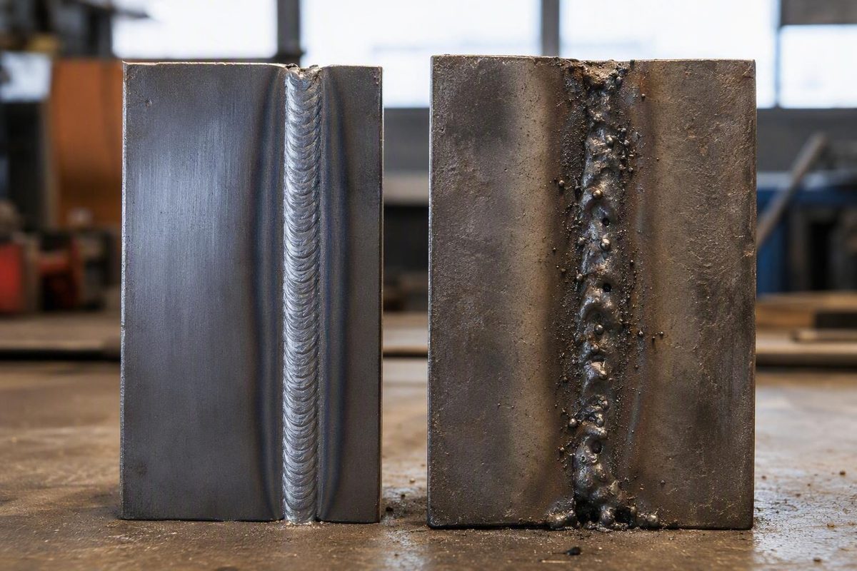
The difference between good vs. bad welding is not simply a “pretty bead” versus an “ugly bead.” A consistent weld face can indicate controlled movement, preparation, and process setup. It cannot, by itself, prove strength, penetration, fusion, internal soundness, or compliance with a drawing, welding procedure specification (WPS), project specification, or governing code.
Treat appearance as the first layer of inspection. Visible symptoms tell you what to examine, measure, verify, or test next; they are not shortcuts to a final pass-or-fail decision.
Good vs. bad welding at a glance
Start with the overall bead shape. Then inspect the toes, starts, stops, crater, and surrounding material.
| Generally positive visual signs | Warning signs requiring investigation |
|---|---|
| Consistent width and contour | Unexplained changes in width, height, or profile |
| Stable placement along the joint | Wandering travel line or incomplete joint coverage |
| Size appropriate to the joint and specified dimensions | Underfill, excessive reinforcement, or an obviously unsuitable size |
| Smooth transitions at both weld toes | Grooves beside the toes, sharp lips, or rolled-over edges |
| Orderly starts, stops, and restarts | Abrupt starts, poor tie-ins, or conspicuous depressions |
| Properly filled final crater | Unfilled crater, crater void, or visible crater indication |
| No obvious surface cracks or pores | Cracks, pinholes, clustered porosity, or cavities |
| No apparent overlap or trapped surface slag | Metal rolled over the base material without apparent fusion, or slag exposed between passes |
| No unintended opening through the workpiece | Burn-through or a collapsed root area |
| Process-appropriate surrounding surface | Sudden, unusual, or excessive spatter |
These are screening characteristics, not universal acceptance categories. “Good” and “bad” are convenient workshop terms, but formal acceptability depends on measured conditions and the requirements controlling the job.
A groove beside a weld toe, for example, is a recognizable condition called undercut. Whether a particular groove is acceptable cannot be decided without its dimensions, location, and the applicable acceptance criteria. Similarly, a convex weld is not automatically bad, and a flat weld is not automatically good. Joint type, process, position, material, thickness, fit-up, and specified weld dimensions all influence the intended profile.
Ripple pattern, spatter, convexity, and coloration require the same context. Limited removable spatter may be expected with some flux-based processes. Color can vary with material, shielding, heat exposure, and cleaning. None of these characteristics is a universal pass-or-fail signal.
Most importantly, an attractive face can conceal incomplete penetration, lack of fusion, inclusions, internal porosity, or cracking. Visual inspection primarily evaluates accessible surfaces and external dimensions; it does not certify internal soundness.
Face-versus-cross-section graphic brief: Show two welds with similarly neat faces beside their cross-sections. Label the weld face, toes, root, fusion boundaries, penetration, and any internal void or unfused area. The caption should state: “Similar surface appearance does not guarantee similar internal soundness. Examples are instructional and are not universal acceptance standards.”
What a well-formed weld usually looks like
A well-formed weld usually looks deliberate. Its width, height, placement, and travel line remain reasonably consistent where the joint geometry does not require a change. That consistency is evidence of process control, not proof of mechanical performance.
Follow the bead’s path. The weld should track the intended joint and cover the required area. Unexplained wandering, abrupt width changes, or uneven deposition may indicate changes in technique, fit-up, access, preparation, shielding, or operating conditions.
Inspect the weld toes. The toes are the boundaries where the weld face meets the base material. A promising weld blends into both workpieces without an obvious groove, rolled edge, or sharp unfused lip. Visible surface tie-in is useful evidence, but it does not establish fusion below the surface.
Evaluate size and contour against the job. Do not praise or reject a bead merely because it is flat, concave, or convex. The appropriate contour depends on the weld type, joint, position, process, and specified dimensions. Measure the features controlled by the drawing or procedure instead of comparing the weld with a generic photograph.
Check starts, stops, restarts, and craters. The beginning should tie into the intended joint. Stops should not leave an obvious depression, ledge, or void. A restart should form an orderly transition rather than a visibly underfilled or piled-up area. A filled final crater is a positive visual sign.
Look for surface continuity. Visible cracks, pinholes, cavities, trapped slag, undercut, overlap, underfill, and burn-through require further evaluation. Their absence is encouraging, but it means only that those conditions were not found on the accessible surface.
Evenly spaced ripples can indicate consistent movement. The familiar “stack-of-dimes” appearance, however, is an aesthetic pattern—not proof that the weld fused through the intended boundaries or achieved the required root condition. A plain-looking weld may be acceptable, while a highly photogenic one may contain hidden discontinuities.
Spatter also needs context. Some flux-based processes can leave limited, removable spatter around an otherwise controlled bead. A sudden increase, heavy adhesion, or highly irregular distribution is more useful as a troubleshooting clue, especially when it appears with an unstable arc or changing weld profile.
Treat coloration cautiously. Material, shielding, heat exposure, cleaning, and process all affect surface appearance. Carbon steel, stainless steel, and aluminum should not be judged by one universal color chart. If the project controls oxidation or final surface condition, apply its material-specific requirements.
A practical visual checklist is:
- Consistent placement, width, and contour where joint geometry is stable
- Size appropriate to the specified weld
- Smooth toe transitions and visible surface tie-in
- Orderly starts, stops, and restarts
- A filled final crater
- No obvious surface cracks, pores, undercut, overlap, exposed slag, underfill, or burn-through
- Spatter and coloration interpreted in process and material context
- Measurement or further examination where appearance cannot answer the question
Visible warning signs and what they mean
A discontinuity is an interruption in the expected structure or shape of a weld. It is not automatically a rejectable defect. Its type, size, location, orientation, extent, and applicable acceptance criteria determine the required action.
Surface porosity appears as individual pinholes or clusters of small voids. The cavities form when gas becomes trapped as the weld solidifies. Possible contributors include dirty base material, moisture, contaminated consumables, inadequate shielding, drafts, or technique. Porosity, overlap, undercut, cracking, and incomplete penetration are illustrated in this weld-quality inspection overview.
Undercut is a groove in the base material beside a weld toe. Because the groove reduces the local cross-section, it should be located and measured against the controlling requirements. The groove alone does not establish which cause produced it.
Overlap, sometimes called cold lap in general shop language, occurs where deposited weld metal flows onto the base material without properly fusing at the edge. It can resemble a rounded shelf or rolled lip. Slow travel, unsuitable manipulation or angle, excessive deposited metal, and an unfavorable heat balance are possible contributors.
Lack of fusion means the weld metal has not bonded properly with the base material or a preceding weld pass. A visible rolled edge can suggest it, but lack of fusion may also remain hidden beneath a smooth face.
Slag inclusions are trapped nonmetallic material. Slag exposed at a toe or between layers may be visible after cleaning; internal inclusions may not be. These conditions and their possible causes are also summarized in UTI’s overview of common welding defects.
Cracks may run along the weld axis, cross it, occur at a toe, or appear in the final crater. Visible cracking calls for documentation and escalation, but formal disposition must come from the applicable requirements and authorized personnel—not a universal online rule.
Underfill leaves the weld face or joint area below the intended profile. It can occur along part of the bead or at a start or stop. Because the concern is dimensional, identify its location and measure it.
Excessive reinforcement is weld metal projecting beyond the intended contour. An overly high or abrupt profile may point to an unsuitable balance of deposition, travel, and operating conditions, but acceptability remains specification-dependent.
Burn-through is an unintended opening or collapsed area where the molten pool has penetrated through the workpiece. Its significance depends on the joint and intended root condition, but it should be evaluated rather than concealed.
Unfilled craters and poor start-stop transitions appear as depressions, abrupt ridges, gaps, or poorly integrated restarts. They should be cleaned as permitted, examined, and measured where appropriate. Covering a questionable area with another pass does not establish that the underlying condition has been resolved.
Irregular profile is a symptom, not a diagnosis.
Spatter consists of expelled metal droplets deposited around the weld. It lies outside the weld rather than being a discontinuity within the weld metal. Some process-dependent spatter may be expected, but a sudden increase can still indicate an operating, shielding, contamination, consumable, technique, or circuit problem.
Annotated defect-gallery brief: Use a cleaned weld-face image labeled with the bead face, both toes, final crater, undercut groove, overlap edge, surface pores, exposed slag, and surrounding spatter. Add the caption: “The image identifies surface conditions only. Internal fusion, penetration, and soundness cannot be determined from the face photograph.”
From bead symptom to possible cause
Troubleshooting should be controlled and comparative. Similar-looking welds can result from different errors, and several interacting errors can produce one symptom. Use appearance to choose checks—not to declare a root cause.
| Visible symptom | Possible causes—not a certain diagnosis | What to verify | Safest next step |
|---|---|---|---|
| Surface pinholes or clustered porosity | Contamination, moisture, shielding loss, drafts, unsuitable gas coverage, consumable condition, technique | Base-metal cleanliness, consumable condition, gas supply and connections, specified flow, shielding coverage, environmental conditions, technique | Stop covering the area; correct a verified condition and follow the required disposition and reinspection process |
| Undercut at one or both toes | Excessive current or heat, high travel speed, unsuitable angle, long arc, poor filler placement | Actual settings against the WPS, travel consistency, angle, arc length, placement, access | Measure and document the groove; adjust only within authorized limits |
| Rolled or overhanging edge | Slow travel, poor manipulation, unsuitable angle, excessive deposition, inadequate edge fusion | Travel, work and travel angles, deposition, heat balance, position | Determine whether overlap or lack of fusion is present; do not grind merely to improve appearance |
| Narrow, convex bead | Low current, fast travel, unsuitable arc length, restricted access, fit-up variation | WPS range, actual current, travel, arc behavior, fit-up, consumable | Compare controlled conditions rather than changing several variables at once |
| Wide, flat, irregular bead | Excessive current, slow travel, excess deposition, poor pool control | Settings, travel, manipulation, consumable size, joint geometry | Return to approved variables and inspect for associated surface conditions |
| Suspected lack of fusion | Inadequate heat, excessive travel, unsuitable angle, poor access, contamination, poor pass placement | Procedure, preparation, cleanliness, travel, angle, sidewall and previous-pass access | Escalate for the examination required by the job; surface smoothness cannot rule out hidden lack of fusion |
| Suspected incomplete penetration | Inadequate heat, excessive travel, tight root opening, unsuitable bevel, poor fit-up, misalignment | Root opening, bevel geometry, alignment, root face, WPS variables, accessible root condition | Stop relying on the face and obtain the prescribed root or internal examination |
| Slag exposed at a toe or between passes | Inadequate interpass cleaning, poor access, unfavorable preparation, incorrect pass placement | Cleaning, joint access, pass sequence, groove geometry, manipulation | Remove loose residue only as permitted; do not bury suspected slag under another pass |
| Excessive or suddenly increased spatter | Parameter imbalance, unstable arc, contamination, shielding trouble, consumables, technique, welding-circuit problem | Settings, polarity, connections, contact components, shielding, consumables, work-return path | Check the complete setup systematically before assuming the machine is defective |
| Irregular starts or stops | Unstable initiation, poor tie-in, abrupt termination, inadequate crater fill | Starting and stopping technique, shielding, restart method, crater condition | Inspect the transition and follow the authorized correction or repair process |
| Burn-through | Excessive heat, slow travel, oversized root opening, changing thickness, poor root control | Fit-up, thickness, approved settings, travel, specified root provisions | Stop welding and obtain an authorized evaluation |
Diagnostic overlap is especially important. A narrow, convex bead might result from low current, but it may also result from excessive travel speed. Porosity may originate in dirty material, moisture, inadequate shielding, a draft, or technique. Randomly changing current, voltage, or gas flow can mask one symptom while creating another.
Use a disciplined sequence:
- Confirm the symptom. Clean the surface only as permitted, improve lighting, and inspect from more than one angle.
- Identify what changed. Compare material, fit-up, position, consumable condition, environment, equipment, and technique.
- Verify the procedure. Compare actual variables with the WPS, work instruction, or applicable equipment guidance.
- Check the complete setup. Include shielding delivery, consumables, torch or electrode components, cable connections, and the work-return path.
- Change one authorized variable at a time. Where a trial is permitted, use representative material rather than improvising on consequential production work.
- Reinspect and document. Confirm whether the symptom changed and whether the resulting weld meets the applicable requirements.
Do not make generic current, voltage, gas-flow, travel, or heat-input changes that conflict with a WPS, equipment manual, or site rule. Welder Facts states that its articles are informational, assume proper PPE and ventilation, and are subordinate to equipment manuals and site rules.
Stick, MIG, and TIG welds should not look identical
Process changes appearance. So do material, joint design, thickness, position, shielding method, consumable, and access. A visual rule learned for one process should not be transferred unchanged to another.
Stick welding
A promising shielded metal arc weld is smooth and well formed for the process, follows the joint, maintains a reasonably uniform contour, and provides visible surface tie-in. Because flux and slag are part of the process, a cleaned stick bead may look thicker or less refined than a TIG bead without being unacceptable.
Hobart Brothers’ stick-weld examples show how different operating conditions can produce overlapping face symptoms:
| Stick-welding condition | Possible visible result |
|---|---|
| Current too low | Narrow, convex, irregular bead with poor penetration or fusion |
| Current too high | Wide, flat, very irregular bead with increased spatter and undercut along the edges |
| Travel too fast | Narrow, convex, irregular bead with poor penetration or fusion |
| Travel too slow | Excessively wide, flat, irregular or porous bead with excessive penetration along the edges |
The key lesson is diagnostic overlap: low current and excessive travel speed are associated with the same listed symptoms. A narrow, convex stick bead therefore does not identify its own cause. Current and travel must both be verified, along with arc length, angle, fit-up, consumable behavior, and other applicable variables.
MIG welding
A promising MIG bead generally shows controlled placement and a consistent profile appropriate to the joint. It should tie into the intended surfaces without obvious undercut, overlap, pores, or cracking.
Not every acceptable MIG bead must be perfectly flat or entirely free of spatter. Transfer behavior, shielding, wire, material, position, and joint design influence the surface. The useful question is whether the weld matches the specified dimensions and remains controlled—not whether it resembles one idealized image.
If a MIG bead becomes erratic, investigate more than hand movement. Parameters, wire feeding, consumables, shielding, contamination, contact components, polarity, and the welding circuit may all contribute.
TIG welding
That appearance can demonstrate coordinated movement, but the ripple pattern does not establish sidewall fusion, penetration, or internal soundness.
Color has similar limitations. Shielding and heat exposure influence the surface, but material and governing requirements determine what matters. One color rule should not be applied across carbon steel, stainless steel, and aluminum.
The process-relative comparison is straightforward:
- A cleaned stick bead may remain comparatively thick or textured.
- A controlled MIG bead may be smooth yet retain some process-dependent spatter.
- A TIG bead may show neat, regular ripples.
- Each process must be evaluated against its own procedure, joint requirements, and acceptance criteria.
Inspect the job before, during, and after welding
Finished-bead inspection is only the final stage. Conditions found before welding are less likely to be buried beneath later passes, while in-process checks can catch changes before they affect the entire joint. Industry inspection guidance organizes visual inspection into before-, during-, and after-welding phases.
Before welding
When applicable, review:
- Drawing and weld symbols
- Project specification and governing requirements
- WPS and related work instructions
- Material identity, grade, and thickness
- Filler metal, electrode, wire, shielding gas, and other consumables
- Welder and procedure qualification requirements
- Inspection and testing plan
- Hold points and authorization requirements
- Documentation and repair requirements
Then inspect the physical joint:
- Base-material cleanliness and surface condition
- Alignment and mismatch
- Joint geometry
- Root opening and root face
- Bevel angle
- Accessibility
- Tack-weld condition and placement
- Backing where specified
- Overall fit-up and restraint
- Welding and work-return connections
Root opening deserves particular attention. A gap that is too tight can contribute to inadequate root penetration, while one that is too large can contribute to excessive penetration. The permitted dimensions must come from the applicable procedure, drawing, or specification—not a generic online rule. ESAB’s visual-inspection guidance likewise connects preparation, alignment, cleanliness, root opening, interpass controls, and completed-weld examination throughout the welding workflow.
During welding
Monitor conditions that may be difficult to verify after another layer is deposited:
- Compliance with approved current, voltage, travel, and other WPS variables
- Electrode or torch angle
- Arc length or relevant process control
- Shielding-gas type and specified flow
- Shielding coverage and environmental conditions
- Welding sequence and pass placement
- Preheat or interpass temperature where required
- Cleaning between passes
- Removal of slag and visible contamination
- Condition and profile of each layer before it is covered
- Fit-up movement or distortion
- Welder identification and qualification status where controlled
Do not wait until the cap is complete to investigate exposed slag, poor sidewall access, or an irregular root. Once another layer covers the area, direct visual access is lost.
After welding
Check:
- Correct weld location
- Required length and continuity
- Specified weld size
- Face contour and reinforcement where controlled
- Toe condition and visible tie-in
- Starts, stops, and restarts
- Crater fill
- Visible cracks, pores, undercut, overlap, underfill, exposed slag, or burn-through
- Root condition where accessible
- Dimensional tolerances
- Alignment and distortion
- Surface condition required for subsequent inspection
Useful aids can include adequate lighting, magnification, mirrors, straightedges, tape measures, calipers, fillet-weld gauges, and temperature indicators. Select tools appropriate to the work and its inspection plan.
No universal numerical limit belongs in this checklist because permitted dimensions and discontinuity limits vary with the controlling document. Consequential work may require formal visual inspection by an experienced or qualified welding inspector.
Why a good-looking bead may still need testing
Visual inspection evaluates accessible surfaces and measurable external features. It can reveal conditions such as surface cracking, undercut, overlap, porosity, incorrect size, and poor contour. It cannot rule out internal lack of fusion, incomplete penetration, inclusions, porosity, or cracking.
Testing should be requirement-driven and appropriate to the material, joint, suspected condition, and service. Not every weld needs every method.
A practical testing ladder is:
- Visual and dimensional examination: Confirm location, size, length, contour, accessible root condition, visible discontinuities, and distortion.
- Surface nondestructive examination: Use the method specified for a suspected surface-breaking or near-surface condition.
- Internal nondestructive examination: Use the prescribed method when hidden discontinuities must be evaluated.
- Representative coupon testing: Use destructive testing for procedure work, qualification, training, or an authorized test plan.
- Authorized review: Escalate uncertain findings, unusual materials, proposed repairs, or consequential service conditions.
Liquid penetrant testing is used to identify surface-breaking indications on suitable nonporous materials. It does not reveal a fully enclosed internal discontinuity.
Magnetic-particle testing is applicable to surface and near-surface indications in ferromagnetic materials. Material suitability is therefore essential.
Ultrasonic and radiographic examination can reveal internal discontinuities that visual inspection cannot see. Neither method is universally suitable. These basic method distinctions are summarized in the cited weld-quality inspection overview above.
Destructive tests provide different information and normally belong on representative coupons:
- A bend test places the weld face or root in tension and reveals whether cracking or tearing develops during bending.
- A fillet-break test fractures a fillet-weld coupon so the exposed surface can be examined for fusion, root penetration, porosity, and other internal discontinuities.
- A macro-etch reveals a prepared weld cross-section, including bead profile, fusion boundaries, penetration, and the heat-affected zone.
These tests do not justify casually cutting, bending, or breaking a finished component. Production parts should undergo destructive examination only when an authorized test plan requires it.
Macro-etching involves chemical hazards and is not a do-it-yourself extension of visual inspection. It requires suitable PPE and ventilation, chemical-specific manufacturer instructions, competent control, neutralization, and appropriate disposal practices; a general welding article is not a chemical procedure. Welders Supply discusses bend, fillet-break, and macro-etch evaluation as coupon-based methods and notes the required controls in its inspection and testing framework.
For structural, pressure, transportation, aviation, or other safety-critical work, use qualified inspection and the examination method prescribed by the governing documents. A workshop appearance check cannot replace required testing.
Deciding whether a weld passes, needs repair, or requires escalation
A photograph and a general web checklist cannot determine formal acceptance. A defensible decision requires the applicable drawing, WPS, project specification, material and joint requirements, service conditions, inspection plan, and governing code.
A visible irregularity is not automatically a rejectable defect. First identify the condition, then determine its size, location, orientation, extent, and applicable acceptance limit. Conversely, a weld should not be approved merely because its face contains no obvious warning sign.
Use this action framework:
- Stop and preserve the evidence. Do not immediately cover or blend the area if doing so would erase information needed for evaluation.
- Clean only as authorized. Remove slag or contamination by a permitted method so the indication can be examined.
- Document the condition. Record the component or weld identification, location, process, relevant variables, dimensions, and photographs with scale where permitted.
- Measure the indication. Use an appropriate gauge or measuring tool rather than judging size from an enlarged image.
- Compare it with controlling requirements. Consult the drawing, WPS, specification, code, and inspection plan.
- Obtain the required examination. Use the specified surface or internal method when visual inspection is insufficient.
- Seek authorized disposition. Involve the qualified inspector, welding supervisor, quality function, or responsible engineer as required.
- Repair only when approved. Follow the authorized repair plan and applicable procedure.
- Reinspect the repair. Apply the examination method and acceptance criteria required for the work.
Stop and escalate rather than approving from appearance alone when there is visible cracking, suspected lack of fusion or incomplete penetration, repeated discontinuities, uncertain material identity, questionable procedure compliance, or safety-critical service. Recurring symptoms also deserve escalation because preparation, consumables, equipment, environment, and procedure control can interact.
Repair is not simply “grind it out and weld it again.” Depending on the work, affected material may require authorized removal, cleaning, rewelding under an appropriate procedure, and final examination.
The decision path is:
Visual and dimensional check → governing-document comparison → required surface or internal testing → authorized disposition → approved repair if needed → final reinspection.
Welding guidance has a firm safety boundary. Use the PPE and ventilation required for the work, and follow the equipment manufacturer’s instructions and site rules. Welding involves electrical current, fumes, and ultraviolet radiation, and the publication’s stated safety terms place equipment manuals and site requirements above general article guidance.
The practical hierarchy is straightforward: read the bead for visible clues, verify preparation and process control, measure the result against the job’s requirements, and test or escalate when appearance cannot answer the question. The important distinction is not pretty versus ugly. It is visually promising versus demonstrably acceptable under the procedure and requirements governing the weld.
Frequently asked questions
Can a weld look good and still be bad?
Yes. A smooth, regular face can conceal lack of fusion, incomplete penetration, inclusions, internal porosity, or cracking. Attractive ripples demonstrate visual consistency more reliably than structural soundness.
Inspect accessible surfaces and dimensions, then complete the testing required for the joint and service. A photograph cannot prove strength or compliance.
How can I tell whether a weld actually passes inspection?
Identify the controlling drawing, WPS, project specification, code, material requirements, joint details, and service conditions. Measure the actual weld and compare it with those criteria.
If the decision requires qualified visual inspection, surface examination, internal NDT, or coupon testing, that work must be completed before the weld is declared acceptable. General examples can help identify symptoms, but they cannot supply project-specific limits.
Do low amperage and moving too fast look the same in stick welding?
They can. Both may produce a narrow, convex, irregular stick bead associated with poor penetration or fusion. That overlap is why the weld face cannot identify the cause by itself.
Verify current and travel speed against the procedure, then check arc length, angle, fit-up, consumable behavior, and the rest of the setup. Avoid changing multiple variables simultaneously.
Is spatter always a sign of bad welding?
No. Limited removable spatter may be normal for some processes, particularly those involving flux. Its acceptability depends on the process, surface requirements, and governing criteria.
A sudden or excessive increase remains a useful troubleshooting clue. Check approved parameters, arc stability, shielding, contamination, consumables, technique, polarity, connections, and the work-return path.
When is nondestructive or destructive weld testing needed?
Testing is needed when the governing documents require it, when service conditions justify it, or when visual and dimensional inspection cannot answer the relevant question. Surface methods evaluate suitable surface or near-surface indications, while ultrasonic or radiographic examination may be prescribed for internal conditions.
Destructive methods such as bend, fillet-break, and macro-etch testing are generally used on representative coupons for procedure work, qualification, training, or authorized quality checks. Do not destructively test a finished production component unless the approved test plan specifically requires it.