
How to Read a Questionable Weld and Choose the Right Next Step
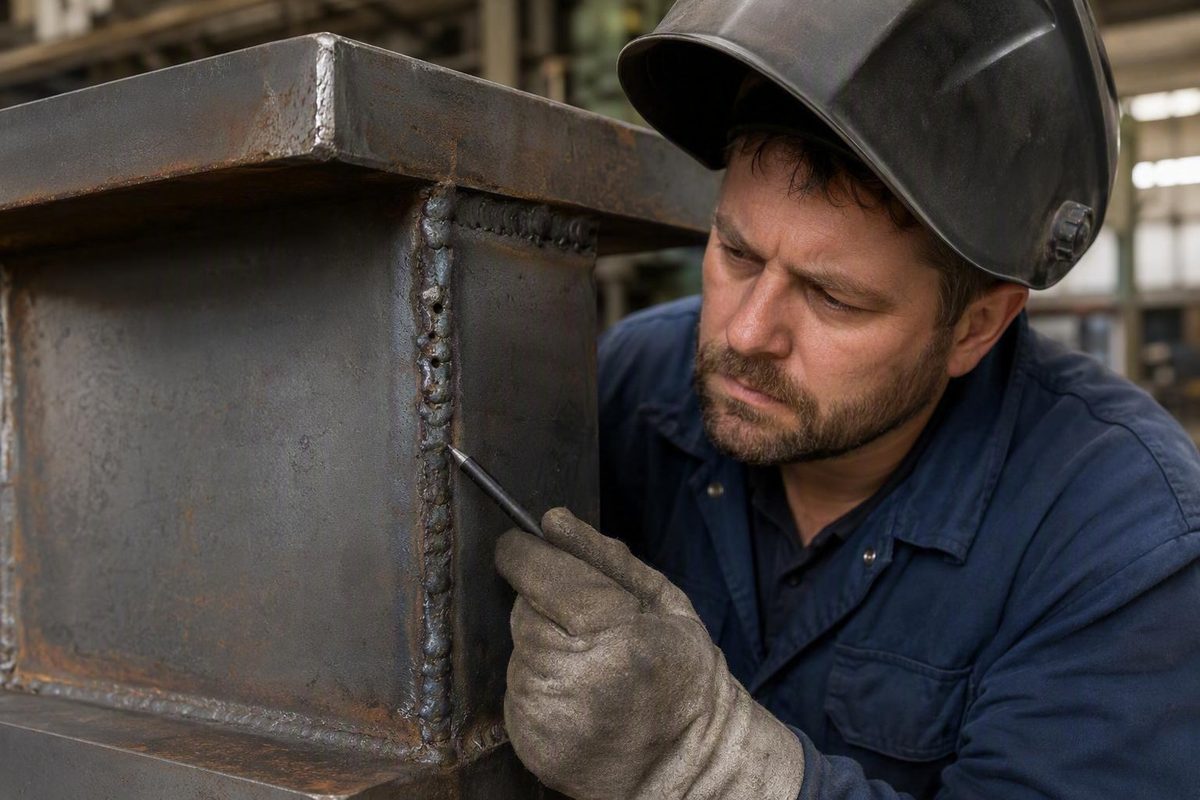
Bad welding is not diagnosed by deciding whether a bead looks “pretty.” A useful assessment asks three separate questions:
- What indication can you see or measure?
- What preparation, setup, equipment, or technique issue might have produced it?
- Does the measured condition meet the drawing, procedure, code, or project specification?
Keeping those decisions separate helps prevent two errors: rejecting a sound weld because it looks rough and accepting an attractive weld that contains hidden lack of fusion, incomplete penetration, or internal porosity.
An Ugly Weld Is Not Necessarily an Unsound Weld
Appearance is evidence, not a verdict. A lumpy bead, scattered spatter, uneven ripples, or an inconsistent start may justify closer inspection without automatically making the joint rejectable. Conversely, a smooth bead does not prove that the weld fused to both sidewalls, reached the required root, or is free of internal voids.
Three terms help clarify the decision:
- Defect: A discontinuity that exceeds the applicable acceptance criteria.
In casual conversation, all three may be called “bad welding.” For acceptance purposes, however, an observed irregularity becomes a rejectable defect only when its type, dimensions, location, or consequences violate the requirements governing the joint.
Visual inspection can identify surface cracks, visible porosity, undercut, overlap, underfill, burn-through, excessive reinforcement, irregular bead shape, poor starts and stops, and accessible root conditions. It should occur before, during, and after welding rather than being limited to a final glance at the bead, as outlined in ESAB’s visual-inspection guidance.
Visual inspection cannot establish everything below the surface. A bead can blend neatly at both toes while hiding incomplete sidewall bonding. The face may appear fully deposited even when the root has not fused adequately. Surface pinholes may reveal porosity, but a clean surface cannot rule out internal gas voids.
That creates three distinct decisions:
- Detection: Identify, locate, and document the indication.
- Diagnosis: Develop and test possible explanations.
- Acceptance: Compare the measured result with the governing criteria.
Do not collapse these into one judgment based on attractiveness. Color, ripple spacing, convexity, and toe appearance vary with process, alloy, thickness, position, joint design, shielding, and the specified profile. “Stacked dimes,” bright metal, or a particular heat tint is not universal proof of quality.
Use a conservative first-pass triage:
- Stop and obtain qualified review for visible cracks or suspected lack of fusion or incomplete penetration.
- Pause recurring production when the same indication repeatedly appears, then investigate the preparation, procedure, consumables, equipment, technique, and environment.
- Hold consequential components involving structural support, pressure retention, lifting, transportation, fatigue loading, or another significant failure consequence.
- Measure cosmetic-looking conditions such as undercut, reinforcement, profile variation, or deposited spatter rather than assuming they pass or fail.
- Do not place a questionable critical component into service until the responsible project authority has determined its disposition.
An ugly weld may satisfy its requirements. A good-looking weld may not. Appearance starts the investigation; the applicable acceptance criteria finish it.
Bad-Weld Symptoms: What Each Indication Looks Like
Begin by naming what you actually see. Loose labels such as “cold weld,” “too hot,” or “bad penetration” can send troubleshooting in the wrong direction, especially when the inside of the joint has not been examined.
| Indication | Visual description | Possible significance | Confirmation needed | Next action |
|---|---|---|---|---|
| Porosity | Pinholes, rounded cavities, or a porous surface; internal porosity may be invisible | Gas voids may reduce the effective section or affect leak tightness, depending on extent and location | Clean the surface and apply the specified visual, surface, or volumetric examination | Hold if the extent is uncertain; investigate contamination, moisture, consumables, and shielding |
| Undercut | Groove melted into the base metal beside a toe or accessible root | Reduces local section and creates a sharper transition | Measure depth, length, location, and frequency | Correct the cause; repair only under an authorized method |
| Underfill | Weld face lies below the adjacent base-metal surface | Insufficient deposited metal or weld cross-section | Measure the profile and required weld dimensions | Determine whether an approved additional pass or more extensive repair is needed |
| Overlap | Weld metal extends onto the base metal with an apparently unfused edge | May represent incomplete bonding at the edge | Close visual examination and any specified additional testing | Do not grind the edge flush and assume fusion exists |
| Excess reinforcement | Buildup above the required face or root profile | May create an unsuitable contour or abrupt transition | Measure height and contour against the governing requirements | Adjust deposition and travel; repair only if required |
| Burn-through | Unintended opening through the base metal, often on thin material | Loss of joint material and root-shape control | Inspect both sides and establish the full extent | Stop and restore the specified geometry under an approved repair |
| Crack | Linear fracture in weld metal or the heat-affected zone | May extend or propagate and therefore warrants high concern | Qualified visual examination and the specified surface or volumetric method | Stop work, mark the area, and obtain qualified assessment |
| Slag inclusion | Trapped nonmetallic material, sometimes exposed at the surface or between passes | Can interrupt fusion and reduce effective section | Remove surface slag; use the specified examination for suspected internal inclusions | Check interpass cleaning, access, angle, and pass placement |
| Lack of fusion | Sometimes visible as an unfused edge, but often hidden at a sidewall, root, or between passes | Incomplete bonding at a fusion boundary | Suitable NDT or destructive testing of a representative coupon | Escalate, particularly on consequential joints |
| Incomplete penetration | Inadequate fusion at the joint root; an accessible backside may show a poor root condition | The required joint depth may not be fused | Root-side inspection, suitable NDT, or coupon sectioning | Compare with the required penetration and escalate when uncertain |
| Spatter | Solidified metal droplets around the bead | Often a cleanup or productivity issue, but may accompany instability or contamination | Determine whether it is isolated deposited material or part of a broader process problem | Clean as permitted and check parameters, polarity, wire delivery, surface condition, and shielding |
| Crater or poor stop | Depression, cavity, pinhole, or crack at the termination | May leave inadequate fill or a crack-prone stop | Clean and inspect the termination closely | Correct the stopping technique and repair if required |
| Irregular width or profile | Wandering edges, changing width, excessive convexity, or abrupt transitions | May indicate unstable travel, feeding, positioning, heat input, or fit-up | Measure dimensions and inspect for related fusion problems | Restore a controlled baseline and test on a coupon |
| Distortion | Warping, angular change, bowing, or misalignment | Can affect assembly, dimensions, and load path | Compare finished dimensions with the drawing | Review restraint, heat distribution, sequence, and any authorized correction method |
Porosity means gas voids within the weld, not merely pinholes visible at the surface. Surface holes do not reveal the complete subsurface extent. Contamination, moisture, consumable condition, drafts, or shielding problems are possible contributors, but the holes alone do not prove which one caused them.
Undercut and underfill are different. Undercut is a groove melted into the base metal beside the weld. Underfill means the deposited face remains below the adjacent base-metal surface. One removes section at the edge; the other reflects insufficient fill. These geometries are distinguished in Xiris’s discussion of underfill and undercut.
Overlap and excess reinforcement are also different. Overlap is weld metal extending onto the base metal without proper fusion at the edge. Excess reinforcement is excessive buildup. A convex weld may exceed a dimensional requirement without containing overlap, while a rolled edge can conceal an unfused boundary even when the overall reinforcement is modest.
The basic geometry can be visualized this way:
Undercut:                    Underfill:

base metal \_ weld base metal \____/ base metal
            ^ groove                  ^ face below surface

Overlap:                     Excess reinforcement:

weld edge rolls outward      weld face rises above required contour
          ^ unfused edge                ^ excessive buildup
These sketches identify features only; they are not acceptance examples.
Burn-through is an uncontrolled opening through the material. Do not confuse it with a specified root profile or intentional penetration. A weld may require complete joint penetration and still have limits on its finished root geometry.
Cracks are fractures in the weld metal or heat-affected zone. They may occur at the centerline, toe, root, or crater. Because the visible line may not show the full extent, simply grinding the surface without an authorized assessment can leave the condition unresolved.
Slag inclusion is trapped nonmetallic residue associated particularly with flux-based processes. Slag sitting on top of a stick or flux-cored bead is not proof that slag is trapped inside. Remove the surface layer properly and inspect the exposed weld before depositing another pass.
Lack of fusion and incomplete penetration are commonly confused. Lack of fusion is incomplete bonding between weld metal and base metal or between adjacent passes. Incomplete penetration concerns inadequate fusion at the joint root. Both may be internal, and neither can be ruled out by a smooth face; ESAB’s welding-defect guide discusses these locations and the limits of surface inspection.
Treat spatter proportionately. Deposited droplets may be primarily a cleanup problem, but a sudden increase can accompany contamination, incorrect polarity, unstable parameter balance, excessive arc length, or poor electrical contact. Spatter is a clue to investigate, not proof that the joint itself is structurally defective.
Trace the Symptom Back to Possible Causes
A symptom-to-cause chart is useful only if its causes remain hypotheses. The same tall MIG bead might result from unsuitable voltage, slow or inconsistent travel, excessive stick-out, poor angle, a wire-feed mismatch, or contamination. If several variables are changed at once, the weld may improve without revealing why.
Organize troubleshooting by where the problem can enter the process.
Preparation
Rust, mill scale, paint, grease, cutting residue, moisture, and other contamination can interfere with arc stability, shielding, wetting, and pool behavior. Possible results include porosity, spatter, interrupted arcs, inclusions, or poor fusion.
Clean to the level required by the process and procedure. That does not always mean polishing every surface, but it does mean removing materials the selected process cannot reliably tolerate. Inspect both sides near the joint when backside contamination can be heated or drawn toward the root.
Fit-up and joint geometry
Record and verify:
- Root opening
- Root face or land
- Bevel angle
- Alignment and offset
- Tack placement
- Clamping and restraint
- Joint accessibility
- Required weld size and penetration
A tight root opening can restrict root access; an oversized opening can make burn-through or excessive penetration harder to control. A narrow bevel can obstruct sidewall access, while an unnecessarily large preparation can increase weld volume, heating, shrinkage, and distortion. Misalignment may also change the effective section and load path.
Do not assume incorrect fit-up can be corrected by increasing the machine setting. More energy cannot solve every geometric problem and may create undercut, distortion, or burn-through elsewhere.
Consumables
Confirm that the electrode, wire, rod, and flux are compatible with the base material, process, shielding system, polarity, position, and governing procedure. Check size as well as classification. An unsuitable diameter can make root and sidewall control difficult within the available operating range.
Keep consumables in the condition specified by their manufacturer and applicable procedure. Moisture, rusted wire, dirty filler rod, damaged coatings, or surface contamination can introduce instability or contamination. For flux-based processes, remove slag between passes and inspect the exposed surface.
Shielding
Shielding problems may result from inadequate delivery, leaks, an empty cylinder, restrictions, a damaged diffuser, a clogged nozzle, excessive gun distance, drafts, or an angle that exposes the pool. Excessive flow is not a dependable cure: it wastes gas and may disturb the shielding envelope.
There is no single correct flow rate for every MIG or TIG application. Required delivery depends on the process, gas, nozzle or cup, position, joint geometry, environment, equipment, and approved procedure. Check the complete delivery path and control drafts before adjusting the regulator blindly.
Heat input and parameter balance
Insufficient energy at the joint or excessive travel speed may contribute to inadequate fusion or penetration. Excessive energy may contribute to undercut, burn-through, distortion, excessive penetration, or an overly wide and difficult-to-control pool.
Bead shape is not a direct heat-input measurement. A high bead may suggest poor wetting, but the profile alone does not establish the internal fusion boundary. Return to a documented procedure or valid machine baseline, verify the actual controls and polarity, and test changes systematically.
Travel speed
The bead may become narrow, inconsistent, underfilled, or poorly tied in. Slow travel may produce excessive buildup, prolonged heating, distortion, overlap, or burn-through, depending on the balance of deposition and energy.
Watch the pool and its edges rather than trying to reproduce a decorative ripple interval. The correct pace is the one that maintains specified placement, fusion, dimensions, and heat control.
Torch or electrode angle
Poor angle can direct energy unevenly, obstruct the view of the leading edge, reduce sidewall access, create unequal leg sizes, or impair shielding. Depending on the process and position, it may contribute to undercut, overlap, slag entrapment, or poor fusion.
Angle cannot be diagnosed from one profile feature alone. Work angle, travel angle, electrode type, position, travel direction, and access all matter.
Welding sequence
Distortion depends partly on how heating and shrinkage accumulate. Tack sequence, restraint, joint balance, pass order, and the order of opposing welds may all affect the finished shape. More clamping is not automatically the answer; use only the sequence and restraint permitted for the work.
For a recurring symptom, use a controlled loop:
- Record the indication.
- Verify preparation and fit-up.
- Check consumables, electrical connections, and shielding.
- Return the settings to a documented baseline.
- Change one plausible variable.
- Weld a representative test coupon.
- Inspect and record the result.
- Repeat only if necessary.
That process turns appearance into evidence rather than guesswork.
A Systematic MIG Troubleshooting Sequence
Randomly changing voltage, wire-feed speed, stick-out, gas, travel, and angle makes MIG troubleshooting inefficient. Use a fixed order so foundational problems are removed before the arc is fine-tuned.
1. Confirm clean material and sound fit-up
Clean the joint and work-clamp contact area. Verify the root opening, edge preparation, alignment, tacks, and access. Look for paint, oil, moisture, rust, and cutting residue on both sides.
Check the welding circuit as well: leads, connections, contact tip, liner, drive rolls, and work clamp. Unstable wire delivery or an inconsistent return path can resemble a parameter or technique problem.
2. Verify wire, polarity, and shielding
Confirm wire classification and diameter, drive-roll setup, contact-tip size, polarity, shielding-gas type, and gas delivery. Inspect the nozzle and diffuser, check for leaks or restrictions, and remove avoidable drafts.
Verify delivery at the gun under operating conditions according to the equipment instructions and applicable procedure.
3. Establish a valid baseline
Use the qualified welding procedure when one governs the work. Otherwise, a machine chart may provide a rational starting point when it matches the material, thickness, joint, position, wire, shielding gas, and transfer mode.
A chart setting is not an acceptance criterion. It is only a starting combination for producing and evaluating a test weld.
4. Assess voltage and wire-feed speed together
The controls must be balanced rather than adjusted as unrelated settings.
In one Weld.com demonstration, excessive voltage produced a wide, hot bead with unstable globular behavior, while insufficient voltage produced a bead that appeared to sit on the surface. An unsuitable wire-feed balance also changed arc stability and profile. These observations came from one setup and are not universal presets; the demonstration is most useful for its systematic comparison of common MIG setup and technique errors.
Listen to the arc and watch the pool, but do not use sound as the sole criterion. Different transfer modes sound different, and a stable-sounding arc does not prove adequate fusion.
5. Check stick-out
An extremely short distance can obstruct visibility and increase the risk of the wire contacting or fusing to the tip.
For short-circuit MIG, the cited presenter used approximately 3/8 to 1/2 inch from the contact tip to the work. That numeric range was setup guidance for the demonstrated context, not a universal specification; follow the wire, gun, machine, transfer mode, procedure, and application requirements in the same MIG demonstration.
Keep the distance consistent throughout the weld. A correct starting position is not useful if it doubles midway through the joint.
6. Verify shielding under actual conditions
Inadequate shielding produced visible holes in the demonstration. Excessive flow provided no observed benefit and wasted gas; forceful flow may also disturb shielding. Before increasing flow, check for leaks, nozzle blockage, draft exposure, excessive gun distance, and an angle that leaves the pool insufficiently covered.
7. Evaluate travel speed
Fast travel may leave a narrow, inconsistent bead with insufficient fill or possible fusion concerns. Slow travel may produce excessive buildup and prolonged heating. Judge travel by pool control, toe wetting, required deposit size, and procedure limits—not ripple spacing alone.
8. Correct gun angle
An excessively steep angle can make the leading edge difficult to read, reduce control, direct energy unevenly, and potentially compromise gas coverage. Diagnose work angle separately from travel angle: one affects placement across the joint, while the other affects how the arc and shielding are directed along it.
Finish with a test-coupon method:
- Use representative material, thickness, preparation, position, wire, and gas.
- Record the baseline.
- Change one variable only.
- Weld long enough to reach steady operation.
- Clean and inspect the coupon.
- Section, bend, or otherwise test a separate coupon when appropriate.
- Record the result before making another adjustment.
Do not use a critical finished joint as a troubleshooting coupon. Where a qualified procedure governs the work, treat it and the project documents as the authority for permitted variables and departures.
Why Warning Signs Change Between MIG, TIG, and Stick
Welding processes create, transfer, and shield molten metal differently. That changes both the likely failure mechanisms and what remains visible after the arc stops. One visual rule cannot be applied universally.
Before diagnosing a bead, record:
- Process and transfer mode
- Base material and thickness
- Joint type and preparation
- Welding position
- Filler or electrode classification and size
- Shielding gas or flux system
- Polarity and principal settings
- Preheat, interpass, and purge conditions where applicable
MIG/GMAW
Prioritize nonuniform width, cracks, surface porosity, craters, spatter, unsuitable profile, erratic starts, and visible toe or root concerns. Investigate voltage–wire-feed balance, stick-out, travel, gun angle, gas delivery, wire condition, liner and tip condition, drive-roll setup, and electrical connections.
MIG can produce a smooth face without confirming fusion. Treat a bead that appears to ride on the surface as a reason to investigate, not as conclusive proof that fusion is absent.
TIG/GTAW
Look for erratic width, burn-through, inadequate filler, excessive width, porosity, undercut, poor starts and stops, and possible tungsten inclusion. Investigate tungsten condition, contamination, arc length, torch angle, shielding, purge quality where required, filler addition, heat control, and travel.
Discoloration may offer information about shielding and heat history on some materials, but it is not a universal pass-or-fail system. Alloy, surface condition, thickness, shielding practice, and project requirements determine its significance.
Stick/SMAW
Check bead dimensions, undercut, cracks, spatter, starts, stops, arc strikes, visible fusion concerns, and slag-related conditions. Electrode storage and condition, polarity, current, arc length, work and travel angles, manipulation, cleaning, and interpass access are central troubleshooting variables.
Residue on top is not the same as slag trapped inside the weld.
Flux-cored and other flux-based processes
Remove slag between passes and inspect toes, valleys, and restarts before covering them. Narrow access, poor bead placement, inadequate cleaning, or an unsuitable angle may contribute to inclusions.
A final face free of slag does not establish that every intermediate pass was cleaned and fused properly. Internal inclusions may require suitable nondestructive examination or testing of a representative coupon.
Across all processes, ripple patterns are technique clues rather than acceptance tests. Uniform ripples may suggest steady manipulation, but they do not replace dimensional checks, fusion assessment, required testing, or comparison with the governing criteria.
What Visual Inspection Can—and Cannot—Tell You
Effective visual inspection begins before the arc. Once a completed weld has a poor root or major distortion, the easiest opportunity to prevent the condition has passed.
Pre-weld inspection
Check:
- Drawing, weld symbol, procedure, and applicable specification
- Qualification documentation where the project requires it
- Material identity and thickness
- Filler or electrode classification
- Joint preparation, bevel angle, root face, and root opening
- Alignment, backing, tacks, and restraint
- Surface and interlayer cleanliness
- Preheat and purge requirements
- Equipment condition and required verification
- Environmental controls
If the preparation does not provide access, the root opening is outside the project requirement, or the wrong filler has been issued, stop before welding and resolve the discrepancy.
In-process inspection
Verify continued conformance with the applicable procedure. Depending on the process, this may include current, voltage, polarity, wire-feed speed, travel speed, shielding-gas type and delivery, preheat, interpass temperature, pass placement, cleaning, sequence, and environmental conditions.
Inspect each pass before it is covered. Surface porosity, incomplete cleaning, poor tie-in, an unfilled crater, or an unexplained parameter change is easier to address while the surface remains accessible.
Post-weld visual inspection
After suitable cleaning and cooling, inspect:
- Weld length and specified dimensions
- Face and accessible root profile
- Leg size, throat, reinforcement, and contour as applicable
- Starts, stops, and tie-ins
- Surface and crater cracks
- Surface porosity
- Undercut, overlap, and underfill
- Burn-through or unsuitable root shape
- Arc strikes and mechanical damage
- Distortion and final alignment
Use adequate lighting, suitable gauges, and practical access to the entire joint. Record dimensions rather than relying on descriptions such as “small,” “deep,” or “not too bad.”
Visual inspection is mainly limited to accessible surfaces. Other methods answer different questions:
- Magnetic-particle examination can reveal surface and near-surface indications in ferromagnetic materials.
- Ultrasonic examination may detect and help characterize internal discontinuities.
- Radiographic examination may provide an image of internal conditions through the examined section.
Selection depends on material, geometry, thickness, access, expected flaw orientation, required sensitivity, governing requirements, and qualified interpretation. No one method is best for every discontinuity. General defect guidance likewise distinguishes visible conditions from internal defects that may require methods such as ultrasonic or radiographic examination.
For training, procedure development, or process evaluation, destructive tests on separate representative coupons can reveal what appearance hides:
- A bend test may expose fusion or ductility problems.
- A fillet-break test exposes the root and fusion surfaces of a test fillet weld.
- A macro-etch cross-section can show penetration, fusion boundaries, pass placement, and the heat-affected zone.
These are coupon methods, not casual tests for a finished service component. Use the specified specimen preparation, method, and acceptance criteria rather than inventing limits. Welders Supply’s testing overview similarly presents bend, fillet-break, and macro-etch examination as coupon-based methods.
Macro-etching uses hazardous chemicals, and destructive testing can involve sharp specimens and mechanically loaded test pieces. Use an established procedure, chemical instructions, ventilation, appropriate PPE, disposal controls, and competent supervision; the cited coupon-testing guidance specifically warns against improvising macro-etch work without chemical precautions.
Inspection finds, locates, measures, and characterizes indications. It does not create acceptance criteria. The result becomes acceptable or rejectable only when compared with the requirements governing the work.
Who Decides Whether a Weld Is Acceptable?
There is no universal appearance threshold separating acceptable welding from bad welding. The same amount of undercut, porosity, reinforcement, or profile variation may be treated differently depending on the material, joint, loading, service, and governing document.
An acceptance decision requires relevant information such as:
- Applicable code, drawing, contract, or project specification
- Welding procedure and permitted variables
- Base material and thickness
- Process and consumables
- Joint type and required weld dimensions
- Type of indication
- Measured size, depth, length, orientation, frequency, and location
- Loading and service environment
- Fatigue, pressure, leak-tightness, corrosion, or temperature demands
- Consequences of failure
- Required inspection method and acceptance criteria
AWS, ISO, and ASME publications are not interchangeable generic rulebooks. Their scopes, terminology, qualification provisions, inspection rules, and acceptance criteria differ. The applicable document and edition depend on what is being fabricated and what the contract invokes.
A practical severity framework can organize the response without inventing limits.
1. Cosmetic or productivity concern
Examples may include removable spatter or a rough appearance that remains dimensionally compliant and has no associated fusion indication. Confirm that the condition is genuinely cosmetic before release.
2. Indication requiring measurement and troubleshooting
Examples include irregular width, visible porosity, undercut, underfill, excess reinforcement, moderate distortion, or recurring poor starts. Measure the condition, inspect related areas, and correct the process cause. Do not declare it acceptable or rejectable from appearance alone.
3. Defect requiring qualified repair
Once the governing criteria establish that a discontinuity is unacceptable, its disposition should follow the authorized project process. That may involve local removal and rewelding, joint removal, or component replacement.
4. Safety-critical condition requiring immediate escalation
Visible or suspected cracks, lack of fusion, incomplete penetration, widespread recurring defects, major distortion, or uncertain damage on a consequential joint warrant a hold and qualified review. ESAB’s defect guidance identifies cracks, lack of fusion, and penetration problems as conditions requiring particular attention while emphasizing that acceptance and repair depend on the applicable requirements.
Cracks and suspected fusion or penetration problems deserve greater scrutiny than spatter that appears to be only deposited material. Cracks may extend beyond the visible line, while incomplete bonding may remain hidden and affect load transfer. Spatter can still signal a process problem, but the droplets do not necessarily interrupt the joint.
Slight porosity and slight undercut have no universal “safe” category. Their measured extent may be permitted in one application and prohibited in another. Neither “all porosity fails” nor “a little undercut never matters” is a defensible general rule.
Refer structural, pressure-containing, load-bearing, fatigue-sensitive, lifting, transportation, and similarly consequential joints to the welding inspector, engineer, manufacturer, or other authority designated by the project. If the governing requirements are unavailable, hold the component rather than guessing.
Repair the Cause, Then Verify the Repair
Repair is an authorization and procedure decision, not an automatic grind-and-reweld response. This is especially important when a component is already in service, the material or heat-treatment condition is uncertain, previous repairs exist, or the governing documents control repair methods.
When an approved repair is appropriate, the general workflow is:
- Identify and mark the affected area.
- Confirm the authorized disposition and applicable procedure.
- Remove the affected material to sound metal while avoiding unnecessary base-metal loss.
- Inspect the excavation before filling it.
- Clean the area and restore the required joint geometry.
- Correct the underlying preparation, fit-up, shielding, equipment, consumable, parameter, or technique issue.
- Reweld under the applicable procedure.
- Perform the specified post-repair visual, dimensional, surface, or volumetric examination.
- Document the disposition and acceptance.
General repair guidance commonly describes removing affected material, cleaning and preparing the base metal, and rewelding, but the acceptable method depends on the actual component and governing requirements. Grinding, chipping, machining, cutting, or gouging may be appropriate in different circumstances; none is universally correct.
Do not simply cover a questionable indication with another pass. Added metal may conceal the original condition or make later examination and removal more difficult. Deposit another pass only when the authorized disposition calls for it and the underlying surface has been prepared and inspected.
Stop improvising and obtain inspector or engineering review when there is:
- Extensive or branching cracking
- Repeated cracking after repair
- Uncertain material identity or metallurgy
- Unknown heat treatment or service history
- Large or deep base-metal removal
- Significant loss of section
- Distortion affecting fit or load path
- A previous repair in the same area
- A discontinuity whose extent cannot be established
- A proposed repair outside the applicable procedure
- A consequential component with uncertain acceptance requirements
Post-repair verification is a separate operation. A completed cover pass proves only that new metal was deposited. It does not establish that the original condition was fully removed or that the repaired joint satisfies its dimensional and examination requirements.
Use this prevention checklist for later work:
- Clean the relevant joint surfaces and work-clamp contact.
- Verify root opening, bevel, alignment, restraint, and access.
- Use compatible, correctly sized, properly stored consumables.
- Confirm polarity, wire delivery, leads, contacts, and machine condition.
- Establish stable shielding and control drafts.
- Start from the applicable procedure or a valid equipment baseline.
- Control travel speed, arc length, stick-out, and work and travel angles.
- Clean and inspect between passes.
- Follow applicable preheat, interpass, purge, and sequence requirements.
- Inspect throughout fabrication rather than waiting for the final bead.
- Use representative coupons before changing production settings.
- Reinspect every completed repair as required by the project.
Keep a troubleshooting and repair log. Record the process, material, thickness, joint, filler, settings, polarity, fit-up, shielding conditions, indication type and location, corrective change, repair details, and inspection result. Over time, the record can help distinguish isolated variation from recurring equipment, consumable, procedure, or preparation problems.
Welding involves current, fumes, and ultraviolet radiation that can injure unprotected workers. Use appropriate PPE and ventilation, and follow the equipment manual and site rules; Welder Facts expressly states that those instructions override its informational articles. Weld-removal and destructive-testing work may introduce additional hazards that must be controlled through the applicable equipment instructions, procedures, and site requirements.
Can an ugly weld still be strong?
Yes. Rough ripples, minor profile variation, or removable spatter do not automatically prove inadequate fusion or dimensions. Position, access, process, and cleanup can all affect appearance.
That does not justify accepting an ugly weld without inspection. Measure it, check for cracks, porosity, undercut, overlap, and accessible root problems, then compare the findings with the governing requirements. “Ugly but strong” must be demonstrated by relevant inspection or testing, not assumed.
Can a good-looking weld still be defective?
Yes. A smooth face may conceal lack of fusion, incomplete root penetration, internal porosity, slag inclusion, or another subsurface discontinuity. Visual inspection cannot directly examine every internal fusion boundary.
Whether additional examination is needed depends on the suspected flaw, material, geometry, access, project requirements, and consequences of failure.
What is the difference between lack of fusion and incomplete penetration?
Lack of fusion is incomplete bonding at a fusion boundary. It can occur between weld metal and base metal, along a groove sidewall, or between adjacent passes.
Incomplete penetration means the joint has not fused adequately at the root to the required depth. A weld may have sidewall lack of fusion even when the root appears adequate, or incomplete root penetration while the face appears uniform. Confirmation may require root access, suitable nondestructive examination, or testing of a representative coupon.
Can bad welding be ground out and rewelded?
Sometimes, but not automatically. Grinding may be part of an authorized repair when it can remove the complete affected area without unacceptable base-metal loss. Other situations may call for machining, chipping, cutting, gouging, or replacement.
The area should be taken to sound metal, inspected before filling, restored to the required geometry, rewelded under the applicable procedure, and reinspected. Cracking, repeated repairs, uncertain materials, extensive removal, and consequential components require qualified review rather than an improvised grind-and-cover pass.
When should a qualified welding inspector or engineer evaluate the weld?
Obtain qualified evaluation when:
- A crack is visible or suspected.
- Lack of fusion or incomplete penetration may be present.
- Indications recur after preparation or settings have been corrected.
- The discontinuity may be internal.
- The applicable acceptance criteria are unclear.
- The proposed repair may alter the material, heat treatment, dimensions, or load path.
- The component is structural, pressure-containing, load-bearing, fatigue-sensitive, used for lifting or transportation, or otherwise consequential.
- The component has entered service or has an uncertain repair history.
The decision path is straightforward: identify and measure the indication, record the process and joint conditions, test possible causes systematically, and compare the result with the governing requirements. Appearance starts the investigation but does not finish it. When the joint is consequential, the condition may be internal, or the repair method is uncertain, hold the component and obtain qualified inspection or engineering direction before service.