
MIG Welding Equipment: What You Need and What Must Match
Build a complete MIG setup by matching power, wire, gun, gas and work leads. Check duty cycle, hidden costs and equipment faults before adjusting settings.
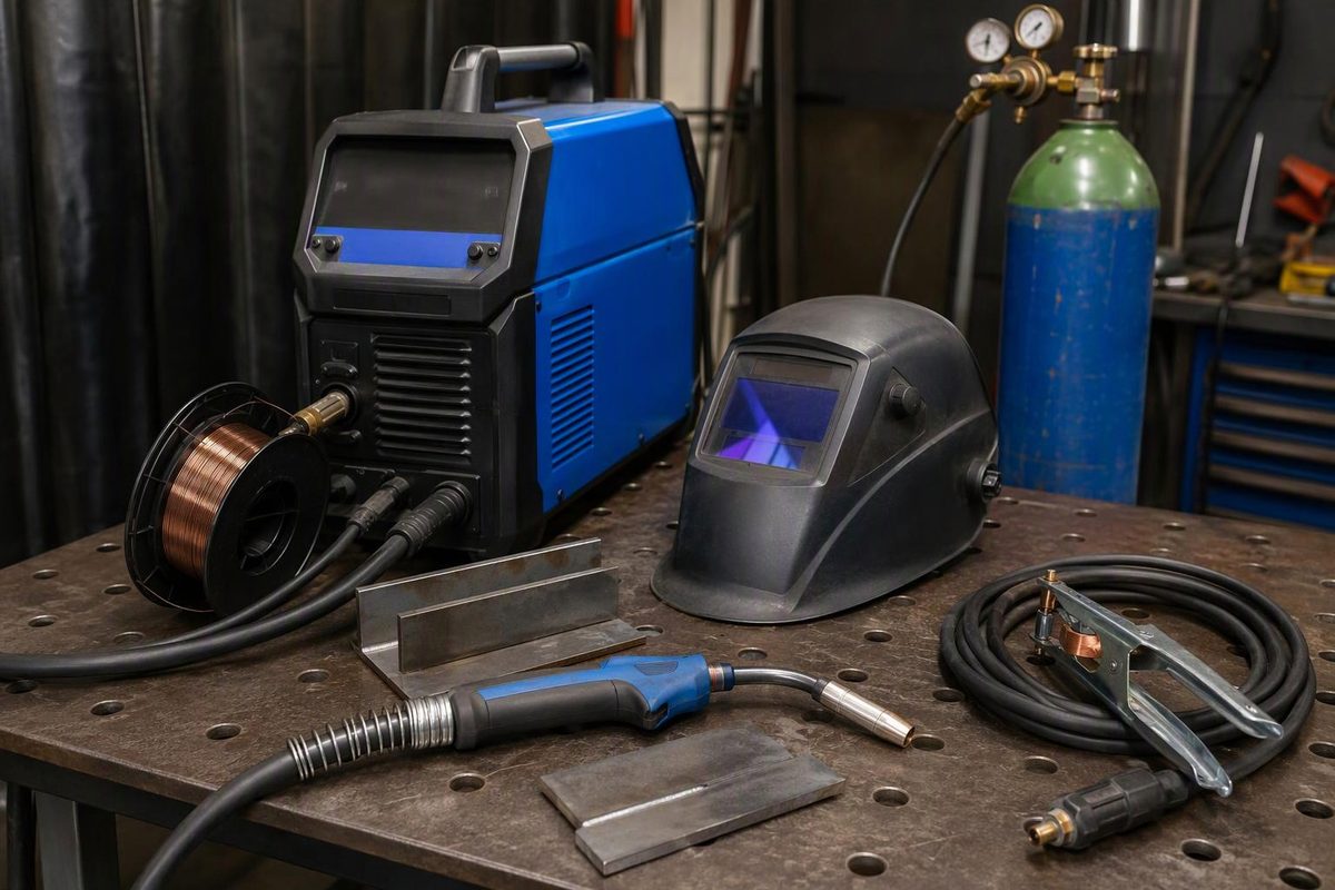
A complete MIG welding setup needs more than a power source: it needs a compatible wire feeder and gun, matching feed components, filler wire, shielding gas and delivery hardware, a sound work-return circuit, and protection for the operator and surrounding area.
Buy these as a matched system, not as separate accessories chosen by price. A machine with enough output can still weld poorly if the wire feeds unevenly or the gas never reaches the puddle.
This guide covers conventional gas-shielded MIG, commonly called GMAW. A “gasless MIG” setup uses self-shielded flux-cored wire—a different process with wire-specific setup requirements. See MIG welding without gas if that is your intended use.
The equipment checklist
| Component | What to verify before buying |
|---|---|
| Power source and wire feeder | MIG capability, available input power, output range, duty cycle, wire-feed range and supported spool sizes |
| MIG gun | Power-pin and trigger connections, current/duty-cycle rating for the intended gas, cable reach and access to the joint |
| Feed components and consumables | Drive-roll groove and size, guides, liner, contact tip, diffuser and nozzle compatible with the gun and wire |
| Filler wire | Classification suited to the base metal and procedure; diameter supported by both machine and feed system |
| Shielding-gas system | Correct gas, compatible cylinder connection, regulator/flowmeter and hose, plus secure cylinder support |
| Work cable and clamp | Adequate rating and reach, intact insulation, sound terminals and reliable contact with clean metal |
| Preparation and protection | Cleaning tools, fit-up clamps, suitable PPE, fume controls, arc screening and fire protection |
Check the package contents rather than assuming that “MIG-ready” includes everything. Budget separately for anything absent, including the cylinder arrangement and first fill, wire, replacement consumables and electrical installation. Miller’s buying guide specifically identifies PPE, gas and consumables as costs beyond the welder itself.
Choose the power source around the work
Start with the base metal, thickness range, joint design, welding position and required procedure. Then consider how much continuous welding you expect. Thin-sheet tacking and repeated long fillets place different demands on a machine.
For conventional MIG, look for constant-voltage DC output with a compatible constant-speed feeder. Voltage and wire-feed speed are the preset controls; current generally rises as wire-feed speed rises. A basic constant-current stick/TIG power source is not an interchangeable substitute simply because a feeder can be attached. Lincoln Electric explains the CC/CV distinction, including the limitations of feeders designed to work on CC output.
Compare these details:
- Input requirements: voltage, phase, circuit requirements and the output available on the supply you actually have. Follow the exact manual and applicable electrical codes; have a qualified electrician resolve installation questions.
- Usable output range: enough capacity for the specified joint, but also suitable low-end control for your thinnest work. A headline maximum amperage is not a complete selection criterion.
- Duty cycle at the required output: compare ratings at equivalent welding conditions, not percentages alone.
For example, a rating of 30% at a specified output means three minutes of welding followed by seven minutes of cooling in a ten-minute period under the stated conditions. It does not mean 30% at every setting. Use the machine’s duty-cycle chart and operating instructions, not the thermal shutdown as your normal stopping point. Miller’s duty-cycle guide explains this rating.
Match the wire path and gun
The wire must travel from spool to contact tip without slipping, being crushed or encountering excessive resistance.
Common drive-roll choices are smooth V-grooves for solid steel/stainless wire, U-grooves for soft aluminum wire and knurled grooves for flux-cored wire. These are selection guides, not permission to ignore the feeder manufacturer’s specified parts. UNIMIG’s drive-roll guide explains how groove shape supports the different wires.
Check the entire path when changing wire diameter or type—not just the contact tip. Confirm the roll groove, guides, liner and tip against the equipment instructions. Excessive roll pressure is not a reliable cure for a restricted liner: too much or too little tension can cause feeding problems.
Choose a gun with sufficient current and duty-cycle capacity, but avoid unnecessary weight and cable length. Check which shielding gas the gun rating assumes: a rating with pure CO₂ is not automatically equivalent to one with an argon blend. Bernard’s gun-rating guide explains how gas choice affects gun heating.
An air-cooled gun is the simpler arrangement; a water-cooled system adds a cooler and hoses and may suit sustained high-output work. Verify the gun’s connections and liner requirements before purchase. Miller’s MIG gun selection guide covers these trade-offs.
For aluminum, assess feeding capability before buying the welder. A compatible spool gun shortens the distance soft wire must be pushed; a push-pull system is another option. Neither is a universal plug-in accessory. Verify the exact gun/feeder/power-source combination and its ratings. Miller’s aluminum equipment guide explains why spool guns reduce feeding problems.
Select gas for the material and transfer mode
For indoor short-circuit MIG on ordinary mild steel, a common setup is ER70S-6 solid wire, DCEP—electrode positive—and 75% argon/25% CO₂ shielding gas. A .030-inch wire is a useful diameter to consider, provided it fits the joint requirements and machine’s supported range. These choices are not a universal prescription for stainless steel, aluminum or every transfer mode. Miller’s mild-steel setup guide covers wire, polarity and gas selection.
Buy the regulator/flowmeter and fittings for the actual gas, pressure and cylinder connection. Secure the cylinder upright and protect it from impact, heat and electrically live parts, as directed in Lincoln’s cylinder-safety instructions.
Set flow according to the equipment and consumable instructions, checking it with gas flowing. More gas is not automatically better: excessive flow can create turbulence and draw air into the shielding envelope. Also inspect hose connections, gun seating and nozzle spatter. Miller’s shielding-gas guide explains these faults. For alloy-specific selection, see MIG stainless setup by transfer mode.
Check equipment before chasing settings
Use this sequence for a new setup or an unstable arc:
- Verify the configuration. Confirm process, wire classification/diameter, polarity and gas against the manual and applicable welding procedure.
- Inspect with power safely isolated. Check damaged cables, loose connections, gun seating, feed components and consumable condition. Do not open or repair internal electrical equipment without the required qualifications.
- Check wire delivery. Follow the manual’s feeding test and tension adjustment. Look for a restricted liner, worn tip, incorrect roll groove or excessive spool drag before increasing pressure.
- Check the return path. Attach the work clamp to clean metal as close to the weld as practical, and inspect the cable and terminals. The work-return connection is not a replacement for the machine’s protective earth. OSHA’s arc-welding requirements address both work-lead attachment and machine-frame grounding. See the complete welding return circuit for troubleshooting.
- Check shielding, then test settings. Verify delivery at the gun, remove nozzle buildup and control drafts. Use the manufacturer’s parameter chart as a starting point on representative coupons, changing one variable at a time.
Miller’s mild-steel preparation checklist supports checking cables, clean clamp contact, tension and consumables before welding. Bead appearance can guide troubleshooting; it does not establish internal fusion or certify the weld. Critical work needs the specified procedure, qualifications and inspection.
Include protection in the setup
Budget for an appropriate welding helmet, safety glasses with side shields, dry welding gloves, flame-resistant clothing and suitable footwear, plus protection for nearby people. Provide effective fume control—not merely an open door. OSHA warns that outdoor or open workspaces do not guarantee adequate ventilation; local exhaust can remove fume from the welder’s breathing zone, and respiratory protection may be required if other controls do not reduce exposure to safe levels.
Arrange arc screening and fire protection without obstructing ventilation, and follow the applicable hot-work rules before striking an arc. OSHA’s general welding requirements cover these protections for U.S. general-industry workplaces.