
Get Your MIG Welder Set Up Before Adjusting the Arc
Match wire, gas, polarity and feed parts before tuning your MIG welder. Find the first checks for stubbing, burnback, porosity and poor edge fusion.
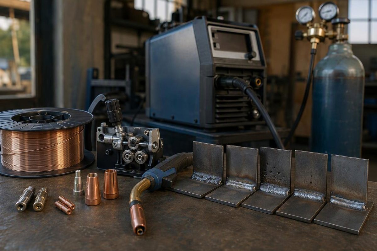
For solid-wire MIG welding of mild steel, match the wire, shielding gas, polarity and feeder parts before adjusting voltage or wire speed. A practical starting combination is .030-inch solid wire, 75% argon/25% CO₂ and DCEP polarity, provided your machine and job support them. Take voltage and wire-speed settings from the machine chart or applicable welding procedure—not a universal setting. This guidance principally covers short-circuit welding; stainless steel, aluminum, spray transfer and pulsed MIG need their own consumables and parameters.
Choose the symptom you see; the tool shows what to check before changing settings.
MIG Symptom Check
Check Feeding and Polarity First
Confirm smooth feeding, DCEP polarity and consistent wire extension. If those are correct, voltage may be too low for the wire speed; adjust only within the machine chart or procedure range.
Solid-wire mild-steel short-circuit guidance. No voltage or wire-speed figures are supplied here; use your machine chart or welding procedure.
Checks and Caveats
Stubbing: Check Feeding and Polarity First
Confirm smooth feeding, DCEP polarity and consistent wire extension. If those are correct, voltage may be too low for the wire speed; adjust only within the machine chart or procedure range.
Surging: Inspect the Wire-Feed Path
Inspect the contact tip, then drive-roll groove and pressure, spool drag, guides and liner. Restrictions or slipping can interrupt feeding. Excessive roll pressure can deform wire and create debris. Isolate input power before servicing; fix feeding before tuning the arc.
Porosity: Check Gas Delivery and Contamination
Check gas delivery, drafts, nozzle blockage and contamination on the joint before changing voltage. Rust, paint, grease and dirt can cause porosity even when the cylinder contains gas.
Poor Tie-In: Check Balance and Pool Position
Check voltage/wire-speed balance, travel speed, gun angle and joint access. Low voltage, insufficient current or excessive travel speed can contribute. Do not automatically slow down: a pool flooding ahead of the arc can also impair fusion. Bead appearance does not prove internal fusion.
Sources: Miller mild-steel setup and parameter guidance; American Torch Tip wire-feed diagnostics; ESAB defect guidance; TWI lack-of-fusion guidance, linked in the article.
Confirm the Process and Machine Capacity
Solid-wire MIG, commonly used to mean gas metal arc welding or GMAW, feeds consumable wire through a gun while externally supplied gas shields the molten pool. Solid MIG wire requires that gas. Self-shielded flux-cored welding uses a different wire and process; closing the cylinder valve does not convert solid-wire MIG into “gasless” welding.
Miller’s wire comparison explains the distinction. For self-shielded wire, use the separate MIG welding without gas guide.
Check the machine manual for supported wire diameters, input-power requirements and output range. A larger wire does not give a small machine more welding capacity. In that same comparison, Miller warns that insufficient output when using .035-inch wire on thicker material can increase the risk of cold lap or lack of fusion.
Check duty cycle at the output you intend to use, not just maximum amperage. A 30% rating over a ten-minute period means three minutes of welding followed by seven minutes of cooling under the specified rating conditions. Follow the machine’s own chart and cooling instructions; Miller’s duty-cycle explanation describes how the rating works.
Establish the Setup Before Striking an Arc
For ordinary mild-steel practice, .030-inch solid wire and 75% argon/25% CO₂—often called C25—are a practical combination when supported by the machine. Smaller .023-inch wire can suit thinner sheet. Select the filler classification for the base metal and job; ER70S-6’s deoxidizers are not permission to weld through paint, oil or heavy rust. These starting choices come from Miller’s mild-steel setup guidance.
Switch off and disconnect input power before changing polarity connections or servicing feeder parts, cables or the gun. Follow the manual’s isolation instructions and applicable lockout rules, and let hot consumables cool. Secure the gas cylinder upright and use a regulator, hoses and fittings intended for the gas and application. Miller’s equipment safety precautions provide the equipment-specific requirements.
Work through the setup in this order:
- Prepare the joint. Remove oil, grease, coatings and other contamination, then clean the weld area to bare metal. Set the gap and any bevel to the joint requirements—not whatever opening remains after clamping.
- Complete the work circuit. Attach the work clamp to clean metal and inspect cable connections and insulation. If the arc remains unstable, check the whole welding work-current path, not only the clamp jaws.
- Verify polarity. Conventional solid-wire mild-steel MIG uses DCEP: gun/electrode positive, work negative. Check especially after changing from self-shielded flux-core.
- Match the feeder parts. The drive-roll groove, liner and contact tip must suit the wire type and diameter. Set spool drag and roll pressure by the manual; excessive pressure is not a cure for a restricted liner.
- Establish shielding. Check the gas supply, hose condition and nozzle for blockage. Miller’s mild-steel guidance gives 20–25 CFH, approximately 9–12 L/min, as a starting range. Use the equipment or procedure requirement where specified, and prevent drafts from stripping shielding away.
The joint, polarity and shielding checks follow Miller’s mild-steel guidance above. American Torch Tip’s feeder guidance explains matching feed components and diagnosing restrictions.
Before welding, wear a correctly selected welding helmet, safety glasses, welding gloves, flame-resistant clothing and suitable footwear. Protect nearby people from arc radiation and make the area fire-safe. Miller’s mild-steel guidance also covers PPE.
Control fumes without blowing away the shielding gas. An open door or outdoor location does not guarantee adequate ventilation. OSHA’s general welding precautions and OSHA’s fume-control guidance explain the necessary protections.
Balance Voltage and Wire Speed With Consistent Technique
On a conventional constant-voltage MIG machine, the two main controls have different jobs. Voltage controls arc length; wire-feed speed primarily determines welding current. They must work together, but neither corrects a contaminated joint or restricted wire feed.
| Variable | Main Effect | What to Watch |
|---|---|---|
| Voltage | Arc length | Balance with wire speed |
| Wire-feed speed | Current and deposition | Match the joint’s fusion needs |
| Travel speed | Heating time per joint length | Avoid outrunning or flooding the arc |
| Electrode extension | Energized wire length beyond the tip | Keep it consistent |
Start with the machine chart or applicable welding procedure for the actual wire, gas, thickness, joint and position. Automatic settings are starting points, not a check of joint preparation or fusion. Miller’s parameter guidance explains balancing settings and reading the resulting bead.
For basic mild-steel short-circuit practice, Miller’s mild-steel guidance cited above recommends roughly 3/8 inch (10 mm) of unmelted wire extension. Measure from the contact tip to the wire’s melting end—not from the nozzle, and excluding arc length. A 5–15° travel angle and a work angle aimed into the joint provide a useful baseline.
Travel speed is not simply a choice between “hotter” and “colder.” Excessive speed can leave inadequate fusion, but moving too slowly can let the pool flood ahead of the arc and also impair fusion. TWI’s fusion guidance explains both mechanisms.
Diagnose the Symptom Before Changing the Controls
Use scrap matching the project’s material, thickness, joint and position. Keep your technique consistent and change one variable at a time so the next bead tells you something useful.
Stubbing Calls for Feed and Polarity Checks First
If the wire stubs into the plate or pushes the gun back, first confirm smooth feeding, correct polarity and consistent extension. With those correct, voltage may be too low for the selected wire speed. Make a small adjustment within the chart or procedure range.
Conversely, an erratic arc burning back toward the tip can indicate excessive voltage relative to wire speed. These relationships follow Miller’s parameter guidance above. Do not treat every burnback as a voltage fault: interrupted feeding can produce it too.
Surging or Repeated Burnback Points to the Feed Path
Inspect the contact tip early, then the roll groove and pressure, spool drag, wire guides and liner. A blocked tip or liner restricts feeding; insufficient roll pressure permits slipping.
Excessive pressure can deform wire and produce debris that worsens liner restriction. American Torch Tip’s diagnostic guidance above explains these faults. Fix the feed problem before tuning the arc, and isolate power before servicing the components.
Porosity Calls for Shielding and Cleanliness Checks
If pinholes or porosity appear, check gas delivery, drafts, nozzle condition and joint contamination before changing voltage. Porosity can result from atmospheric contamination or rust, paint, grease and dirt—not only an empty cylinder. ESAB’s defect guidance describes these causes.
A flow setting alone does not establish that shielding reaches the weld. Check the delivery path and conditions at the nozzle, not just the regulator reading.
Poor Edge Tie-In Does Not Always Mean Travel Is Too Fast
For a narrow, convex bead or poor tie-in at the edges, check the voltage/wire-speed balance, travel speed, gun angle and access to the joint. Miller’s parameter guidance identifies low voltage, insufficient current and excessive travel speed as possible causes.
Do not automatically slow down. As TWI explains, an oversized pool running ahead of the arc can also cause poor fusion. Determine whether the arc is reaching the joint rather than depositing onto a pool that has already covered it.
Record the setup once it behaves consistently. A smooth bead and steady arc are useful diagnostic clues, not proof of internal fusion or compliance with a welding code. TWI’s guidance also explains that subsurface lack of fusion requires appropriate inspection methods. Critical work must meet the applicable procedure and acceptance requirements.