
Identify the Machine Before You Buy Parts, Choose Settings, or Plan a Repair
The legacy 250 and current 255 are separate machines; use the data plate and serial-matched manual before testing, ordering parts or setting a price.
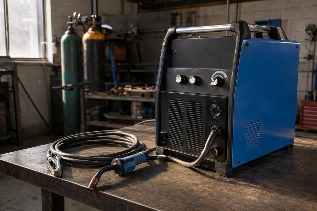
A “Miller 250 MIG welder” may mean the legacy Millermatic 250 or Miller’s current machine in the roughly 250-amp class, the Millermatic 255. They are separate machines, not interchangeable names. Miller identifies the current unit as the Millermatic 255, model 907734 (see Miller’s official product page).
Before buying parts, choosing settings, or estimating a repair, record the older welder’s complete model designation, stock number, serial number, and input-power information. Find the manual that matches those identifiers, then test the machine under load if that can be done safely.
First, determine which “Miller 250” you mean
The legacy Millermatic 250 and the current Millermatic 255 belong to different generations. Do not apply a 255 manual, parts list, electrical requirement, or setup procedure to a legacy 250.
Historical owner discussions mention related designations including the 250MP, 250X, 250XL, and 251. These names can help identify what is in front of you, but the available forum evidence does not establish official specifications or parts interchangeability among them. A 2004 used-machine discussion demonstrates the problem: the prospective buyer did not establish the exact variant, while replies referred to several related models and expressed sharply different opinions. Its approximately $250 asking price is historical context, not a present-day valuation benchmark (see the archived discussion).
Photograph the data plate before moving, powering, or buying anything for the machine. Record:
- Complete model designation, including every suffix
- Stock number
- Serial number
- Rated input voltage, phase, frequency, and any listed input-current information
- Existing input cord and plug configuration
- Gun make and model, if marked
- Gun connector and trigger connection
- Installed wire classification and diameter
- Drive-roll markings and groove type
- Contact-tip size
- Work-lead and clamp condition
- Current polarity arrangement
Use those identifiers to search Miller’s owner-manual archive. Select the manual that applies to the exact stock and serial number, not merely one with “250” in its title. That manual should be the primary reference for input power, controls, polarity, setup, settings charts, maintenance, diagrams, and original parts information.
Choose your path
- You own or are considering a legacy Millermatic 250: Continue with the used-machine inspection, setup, parts, and troubleshooting guidance below.
- You want a new Miller machine in the 250-amp class: Skip to the Millermatic 255 comparison. Do not assume it is a renamed or specification-equivalent Millermatic 250.
Used Millermatic 250 inspection checklist
An older welder can look complete while still being expensive to put into service. Begin by identifying what is present, what fits, and what remains untested.
Inventory the gun, work lead and clamp, regulator or flow gauge, gas hose, cylinder arrangement, wire spool, contact tips, nozzle, liner, drive rolls, input cord, plug, and any adapters. A low purchase price loses its advantage quickly if the machine lacks the components needed for a proper welding test.
| Check | Acceptable evidence | Unresolved risk |
|---|---|---|
| Identity | Legible data plate with complete model, stock, and serial numbers | Manual, parts, and electrical requirements cannot be matched confidently |
| Input power | Nameplate requirements match the available supply and connection | Machine cannot be tested safely or may require electrical work |
| Completeness | Compatible gun, work lead, gas hardware, rolls, and consumables are present | Unknown cost to make the welder usable |
| Wire feed | Wire feeds consistently during a weld without slipping, surging, or binding | Liner, tip, rolls, tension, motor, or control problems may remain |
| Gas delivery | Stable delivery with sound hose and gun connections | Leaks, valve trouble, or missing equipment |
| Gun and trigger | Secure connection, reliable trigger response, serviceable cable and neck | Intermittent control or feeding faults |
| Work return | Clamp attaches securely to clean bare metal; lead and connections are sound | Erratic or absent arc may be mistaken for an internal fault |
| Controls | Voltage and wire-speed controls respond predictably during welding | Worn controls or electronic faults |
| Welding output | Sustained, stable arc on suitable scrap at more than one practical setting | Fan, gas, and wire feed alone do not prove usable output |
| Service support | Applicable manual found and critical parts or repair service identified | Repair cost and downtime remain unknown |
Whenever conditions permit, require a powered welding test under load on clean, suitable scrap. Hearing the fan, watching the wire feed, or confirming gas flow proves only that those functions operate. It does not show that the welder can maintain stable output.
During the test, check:
- Consistent wire feeding from arc start through sustained welding
- Reliable gas delivery
- Responsive wire-speed and voltage controls
- A secure gun connection without intermittent operation
- A clean, tight work-return connection
- Stable arc output for more than a momentary tack
- Abnormal noise, smell, heat, or control behavior
This is a general buyer’s checklist, not a Miller-issued inspection procedure. Keep the purchase inspection external; do not open the machine or attempt internal diagnosis. Welding involves hazardous current, fumes, and ultraviolet radiation, so use suitable PPE and ventilation and follow the equipment manual and site rules.
If the seller cannot confirm the machine’s identity, provide the correct input-power arrangement, or demonstrate welding output under load, value it as an untested machine with unresolved repair risk—not as a known-good welder.
Find starting settings without misreading the voltage dial
A generic MIG calculator can disagree with the numbers around an older Millermatic 250 voltage control without either number necessarily being a direct substitute for the other.
In a December 2008 Miller-hosted forum thread, users described calculator figures as loaded arc voltage, while another post said the markings around an older 250’s dial represented approximate open-circuit voltage. Voltage changes once an arc is established, so forcing the front-panel dial to equal a generic calculator number may produce the wrong result. A moderator identified on the forum as Miller Electric service technician Kevin Schuh also supplied a separate Millermatic 250 chart, reportedly with different values, but its contents are not reproduced in the available discussion text (review the original settings discussion).
The figures below were transcribed from a calculator by a participant in that 2008 thread. They are historical, user-generated starting points for .030-inch solid wire. They are not official settings for every Millermatic 250, guaranteed results, or necessarily equivalent to front-panel positions.
| Steel thickness | Historical voltage range | Historical wire speed |
|---|---|---|
| 18 gauge | 16–17 V | 150–175 IPM |
| 16 gauge | 17–18 V | 220–250 IPM |
| 14 gauge | 17–18 V | 250–340 IPM |
| 1/8 inch | 18–19 V | 280–300 IPM |
| 3/16 inch | 18–19 V | 320–340 IPM |
| 1/4 inch | 21–22 V | 360–380 IPM |
Before using any table, confirm:
- Exact machine and applicable manual
- Filler-wire classification and diameter
- Base material and measured thickness
- Shielding-gas composition
- Drive-roll and liner suitability
- Polarity required for the filler and machine
- Whether the reference gives loaded arc voltage or a control position
Treat the serial-specific manual and model-specific chart as the primary references. Use a generic calculator or old forum table only to establish a test range.
Tune thin sheet with a test coupon, not a single magic setting
For 18-gauge steel with .030-inch solid wire, the historical forum range is 16–17 volts and 150–175 inches per minute. That is an old, user-transcribed starting range—not a guaranteed setting or necessarily the number that should appear on the welder’s dial.
Use a controlled adjustment process:
- Prepare clean scrap matching the job’s material, thickness, coating condition, and joint geometry.
- Confirm the filler wire, shielding gas, drive-roll setup, and polarity.
- Begin with the range in the applicable Miller manual.
- Make a short test weld using the intended gun angle and travel direction.
- Inspect arc stability, bead shape, fusion, penetration, and distortion.
- Change one variable at a time.
- Repeat until the setup produces an acceptable joint consistently.
Burn-through is not controlled by voltage alone. Fit-up gaps, joint design, edge condition, travel speed, gun technique, shielding gas, actual machine output, and the time the arc stays in one place all affect the result.
If the dial and calculator disagree, do not assume the machine is defective. The discrepancy may reflect open-circuit versus loaded voltage, a different control scale, or a model-specific chart. Prioritize the serial-matched manual, then tune according to weld response on matching scrap.
Do not rely on a broad rule that solid wire always uses one polarity and flux-cored wire the other. Verify polarity for the exact filler classification and the machine’s documented terminal arrangement.
The sequence must still produce the required fusion, profile, and joint integrity.
Verify replacement guns and consumables before ordering
HTP America/USA Weld lists an M25-style replacement gun, nozzles, contact tips, adapters, steel liners, trigger components, neck parts, and consumable kits for the Millermatic 250 (view the retailer’s Millermatic 250 collection).
Treat that catalog as a compatibility lead, not proof that every item fits every stock number, serial range, original gun, or modified machine.
Complete this worksheet before ordering:
| Ordering detail | What to record |
|---|---|
| Welder identity | Full model, stock number, and serial number |
| Existing gun | Manufacturer and model, if legible |
| Machine connection | Gun connector style and dimensions |
| Trigger circuit | Plug type, pin count, and existing arrangement |
| Cable | Required length and current condition |
| Liner | Material, length, and compatible wire range |
| Filler wire | Material, classification, and diameter |
| Contact tip | Bore size, thread, length, and gun family |
| Nozzle | Slip-on or threaded style, bore, and recess |
| Drive rolls | Diameter, groove profile, and wire-size markings |
| Adapters | Existing gun, trigger, or tip adapters |
Send the information and photographs to the supplier and obtain written compatibility confirmation. Alternatively, verify every component against the parts manual matching the welder’s stock and serial number.
Do not build a restoration budget from displayed catalog prices alone. Availability and pricing change, and the gun may be only one missing item among the regulator, hose, work lead, drive rolls, plug, wire, cylinder arrangement, and repair parts.
If wire and gas work but there is no arc
Start outside the cabinet. With the machine configured and operated according to its manual:
- Attach the work clamp to clean, bare metal.
- Inspect accessible work-lead, gun, and machine connections.
- Check the gun cable for obvious damage.
- Confirm that the wire reaches the work correctly.
- Confirm the symptom only through a normal welding test.
A poor work-return path can imitate a machine-output problem.
In a 2005 Millermatic 250 forum case, a machine continued feeding wire but produced no welding output. Kevin Schuh, identified in the discussion as a Miller Electric service technician, said an open normally closed thermostat in the rectifier could allow feed and gas functions to operate while preventing weld output. The thread also raised poor harness or PCB connections, a main-board fault, and SCR-control problems as possibilities (read the historical no-output case).
Wire feed and gas without an arc do not prove that the thermostat failed. The owner in that single case reported part number 154246, but the thread does not establish that number as correct for every Millermatic 250 stock number or serial range.
Do not bypass the thermostat or reproduce the thread’s energized meter behavior. Follow the applicable manual and workplace rules, and refer internal continuity, rectifier, SCR, harness, or control-board diagnosis to qualified service.
For a repair estimate, give the service provider:
- Full model, stock number, and serial number
- Applicable manual or schematic revision
- Input-power configuration
- Exact sequence of events before the failure
- Whether wire feed and gas operate
- Whether output is absent or unstable
- Photographs of external connections
- Known repair or modification history
That information helps distinguish a documented fault from open-ended troubleshooting.
Repair the 250 or move to a Millermatic 255?
There is no universal answer. A complete legacy machine that welds properly may remain useful for straightforward shop work. An unidentified, incomplete machine without an under-load test can become a poor bargain even at a low asking price.
| Decision factor | Repair the legacy 250 when… | Consider the 255 when… |
|---|---|---|
| Welding output | It passes a sustained test or has a documented fault | Output is unverified or faults are intermittent and costly to isolate |
| Feed system | Gun, liner, rolls, and feeder are serviceable | Several feed components are missing, worn, or incompatible |
| Parts and service | Critical parts and qualified repair support are available | Key components cannot be sourced or downtime is unacceptable |
| Process needs | Conventional MIG or flux-cored work meets shop needs | Pulsed MIG or stored programs solve a production problem |
| Accessories | The machine is already complete | Missing equipment and repairs substantially narrow the price gap |
| Controls | Existing controls are adequate | Locks, limits, and repeatable program recall are valuable |
| Input power | The shop has the correct documented supply | A supported 255 input arrangement better fits the facility |
| Downtime | The shop can tolerate diagnosis and repair | Predictable availability matters more than retaining old equipment |
The Millermatic 255 is a separate machine. Miller documents model 907734 for MIG, pulsed MIG, and flux-cored welding from 208/240-volt single-phase input. The machine weighs 84 pounds and has a 7-inch color LCD, Auto-Set Elite, saved programs, parameter locks and limits, and USB support for software updates, backups, and program transfer.
The cited package includes:
- A 15-foot, 250-amp MDX-250 gun configured for .035- and .045-inch wire
- A 10-foot work cable and clamp
- A regulator and gas hose
- Extra contact tips
- A material-thickness gauge
- Reversible .035/.045-inch drive rolls
Shielding gas, welding wire, PPE, an aluminum push-pull or spool gun, and flux-cored drive rolls are not included. Aluminum welding requires optional feeding equipment (see Miller’s specifications, package contents, and exclusions).
Miller says the 255 can weld mild steel and aluminum up to 1/2 inch, but the cited page does not define joint design, welding position, filler, shielding gas, pass count, or duty cycle for that claim. Miller also specifies a generator or engine-driven welder rated at 12,000 watts or more for full output and says smaller generators limit output. Its statements that pulsed MIG can reduce spatter, heat input, distortion, grinding, and rework are manufacturer claims, not independent comparative findings.
Repair deserves consideration when the legacy 250 passes an under-load test or a qualified technician identifies a specific, economical fault, and the machine still meets the work’s process and control requirements. Replacement deserves stronger consideration when identity or condition cannot be confirmed, important parts or accessories are unavailable, downtime is expensive, or pulsed MIG and programmable controls provide a measurable shop benefit.
Before committing money either way:
- Photograph the legacy machine’s data plate.
- Retrieve the manual matching its stock and serial number.
- Inventory every missing or questionable accessory.
- Require a safe welding test under load.
- Obtain written parts-compatibility and repair estimates.
- Treat historical settings and aftermarket catalogs as starting leads only.
- Compare unresolved repair risk with the Millermatic 255’s documented processes, controls, included equipment, exclusions, and power requirements.
If the older machine cannot be fully identified, tested, or economically supported, price it as a repair project—not as a working equivalent of the Millermatic 255.