
14-Gauge Steel MIG Settings: Voltage, Wire Feed and Test-Weld Checks
Start with sourced MIG settings for 14-gauge mild steel, matched to wire and gas, then diagnose burn-through, stubbing and poor fusion.
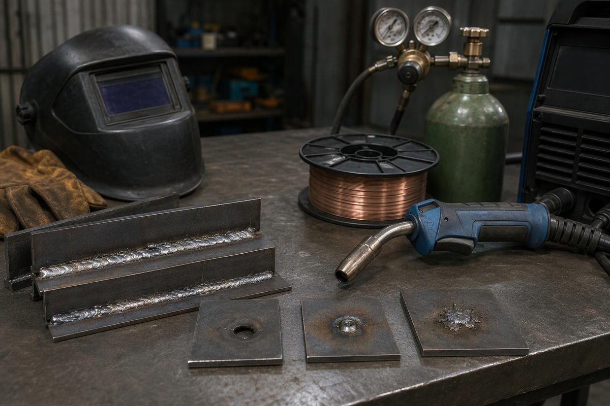
For 14-gauge mild steel with .030-inch solid wire and 75% argon/25% CO₂ shielding gas, 18 volts and 225 inches per minute (ipm) wire feed are a published starting point for flat butt joints and horizontal fillet welds. With .035-inch solid wire, the corresponding reference is 18 volts and 175 ipm. These come from Lincoln Electric’s GMAW guide, not a universal setting for every joint or welder.
This guidance is for uncoated mild steel using conventional short-circuit MIG. Nominal 14-gauge mild-steel sheet is 0.0747 inch, or about 1.90 mm, thick; measure your stock because tolerances and gauge systems vary. Stainless and galvanized steel have different gauge thicknesses in the Metal Supermarkets gauge chart.
Match the settings to wire and gas
Lincoln’s reference conditions are DCEP—wire positive, a 1/2-inch (13 mm) contact-tip-to-work distance, gas flow of 25–35 cubic feet per hour (12–17 L/min), and travel speed of approximately 18 ipm (0.45 m/min).
| Solid-wire diameter | Wire-feed speed | Voltage with argon/CO₂ blend | Voltage with 100% CO₂ |
|---|---|---|---|
| .030 inch (0.8 mm) | 225 ipm (5.7 m/min) | 18 V | 20 V |
| .035 inch (0.9 mm) | 175 ipm (4.4 m/min) | 18 V | 20 V |
The Lincoln short-circuit table for horizontal fillets and flat butt joints lists 20 V with pure CO₂ and instructs users to decrease voltage by 2 V for an argon/CO₂ blend. The same guide identifies 75% argon/25% CO₂, commonly called C25, as a short-circuit shielding blend for carbon steel.
Use your machine’s matching 14-gauge chart entry first when available. A numbered voltage tap or wire-speed dial is not a volts/ipm display; the numbers above do not translate directly into “setting 3” or “dial 40.” Miller likewise recommends starting with the machine’s thickness, wire-size and material chart.
On a conventional constant-voltage MIG machine, you normally set voltage and wire-feed speed, rather than independently choosing amperage. Wire-feed speed affects current, while voltage influences bead shape and arc behavior. Keep these controls balanced rather than treating either as a standalone heat knob. Miller’s parameter guide explains that relationship.
Tune on a matching 14-gauge test joint
Prepare scrap with the same thickness, joint type, gap and welding position as the work. Remove oil and grease before abrasive cleaning of rust, paint or scale, and establish a clean work-clamp connection. Hold the contact-tip-to-work distance steady so changes in gun distance do not obscure what a setting adjustment does. Miller covers surface preparation and gun-distance effects.
Then diagnose in this order:
- Wire repeatedly stubs into the puddle: Check feeding and gun distance first. If both are steady, increase voltage slightly relative to the existing feed rate.
- Arc is erratic and burns back toward the tip: Check feeding before changing settings; excessive voltage relative to wire feed may need reducing.
- Wide bead or burn-through: Check whether you are traveling too slowly or dwelling at an edge. Excessive feed/current can also contribute. Correct fit-up and technique before simply lowering both controls.
- Narrow, convex bead with poor edge tie-in: Travel may be too fast, current may be insufficient, or voltage may be too low. Reducing heat further can worsen fusion.
- Pinholes or porosity: Investigate shielding and cleanliness before voltage. Turning up the heat does not restore missing gas coverage.
These symptoms and adjustment directions follow Miller’s weld-parameter guidance. Change one variable at a time and record the result.
Where these numbers stop applying
A different gap, joint geometry, welding position, or 14-gauge sheet attached to a much thicker member needs its own trial setup. Do not transfer this table to self-shielded flux-core wire, stick electrodes or TIG. For a gasless wire-feed machine, use the wire-specific chart and flux-core setup checks.
Use proper welding PPE, ventilation and fire controls. Coated stock needs separate preparation and fume precautions; see welding galvanized steel.
Finally, a smooth bead is a diagnostic clue—not proof of fusion or load capacity. Lincoln warns that poor short-circuit procedure control can produce incomplete fusion. For load-bearing or code-governed work, follow the applicable welding procedure and inspection requirements rather than approving the weld by appearance.