
Welder Settings for 1/4-Inch Steel: Where to Start and What to Check
MIG, stick and flux-core setting references for 1/4-inch mild steel, with joint-preparation and troubleshooting checks that matter for fusion.
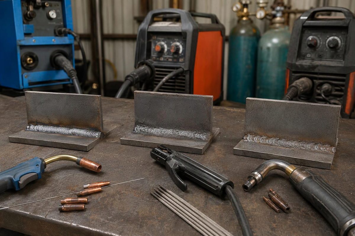
For 1/4-inch (0.250-inch, 6.35 mm) mild steel, choose settings by process, consumable and joint—not thickness alone. Start with your machine’s chart for the selected wire or electrode, shielding gas and thickness. Any required welding procedure specification (WPS) takes priority over a general chart.
These examples concern clean, uncoated low-carbon steel. Don’t transfer them unchanged to stainless, hardened or unidentified steel; first establish what material you are welding.
Setting references by process
The table distinguishes a documented joint-specific setup from consumable operating references. None establishes the required weld size or penetration for your job.
| Process and consumable | Setting reference | Polarity and shielding | Important limit |
|---|---|---|---|
| Solid-wire MIG, .035-inch ER70S-6 | 20 V and 333 inches/minute (ipm) wire feed | DCEP; 75% argon/25% CO₂, called C25 | Documented short-circuit MIG setup for a 1/4-inch overhead tee fillet, not a universal flat, vertical or groove-weld setting. |
| Stick, 1/8-inch Lincoln Excalibur 7018 XMR | 125 A as an initial coupon trial | DCEP preferred; no external shielding gas | A selected starting point within Lincoln’s published 90–160 A DC range, not a thickness-specific procedure. The product supports all positions except vertical down. |
| Self-shielded flux-core, .035-inch Lincoln NR-211-MP | Published operating point: 18–19 V and 200 ipm | DCEN; no external shielding gas | A wire operating reference, not a prescribed 1/4-inch setting. Check it against your machine’s chart for this wire and thickness. |
Sources: Welding Tips and Tricks’ overhead MIG setup, Lincoln’s Excalibur 7018 XMR datasheet, and Lincoln’s Innershield operating guide.
DCEP means electrode positive; DCEN means electrode negative. Verify the connection arrangement in the equipment manual before changing polarity.
On conventional MIG equipment, you normally adjust voltage and wire-feed speed, not amperage independently. Wire feed affects current and penetration; voltage affects arc behavior and bead profile. A numbered speed dial is not automatically an ipm reading. Use the machine manual to interpret it. Miller explains these parameter relationships.
Why the MIG setting is not always 250 amps
Miller’s familiar one-amp-per-0.001-inch rule gives 250 A for 1/4-inch steel, but it is a rule of thumb, not a requirement for every joint. Don’t use that calculation to override a matching machine chart or force .035-inch wire beyond its recommended operating range.
Position and technique matter. The overhead MIG example above uses a 3/8–1/2-inch contact-tip-to-work distance and keeps the arc on the leading edge of the pool. Treat those details as part of that setup, rather than copying only its voltage and wire speed. See the documented overhead setup.
Decide what the joint needs before turning up the welder
A 1/4-inch plate does not automatically need a 1/4-inch fillet weld. Establish the required weld size and penetration from the design or procedure. A tee fillet and a butt joint requiring full penetration are different tasks.
For a groove weld, preparation must let the arc reach the root. If square edges block access, more voltage cannot substitute for the specified joint preparation. Hobart’s guidance identifies inadequate joint preparation, poor arc placement and insufficient heat input as separate causes of poor penetration. See its MIG joint and fusion troubleshooting guidance, sections 9-11 and 9-12.
Before testing:
- Remove contamination from the weld area and establish clean work-clamp contact.
- Check the machine’s supported thickness for the selected process and input supply, plus its duty cycle. Don’t assume maximum dial position means adequate capacity.
- Match the test coupon’s thickness, joint, gap and position to the job.
- Use welding PPE, ventilation and appropriate fire precautions.
For NR-211-MP specifically, Lincoln lists a 5/16-inch maximum plate thickness for .035-inch wire, so 1/4-inch plate falls within that restriction. This does not establish weld size, pass count or machine capability. Its operating guide specifies 1/2–5/8-inch contact-tip-to-work distance—don’t automatically copy a solid-wire MIG distance. Lincoln’s thickness restrictions and operating guide provide those limits.
Tune the test weld in this order
- Check setup first. Confirm polarity, gas where required, steady feeding and sound connections. Porosity calls for checking contamination and shielding—not simply adding heat.
- Stabilize the MIG arc. With feeding and connections verified, persistent wire stubbing can indicate voltage too low for the selected feed speed. An erratic arc burning back toward the tip can indicate excessive voltage. Make small changes, one variable at a time.
- Check travel and arc placement. A narrow, convex bead with poor toe tie-in can result from low current or excessive travel speed. Conversely, crawling along and piling up a wide bead can still produce poor penetration. Keep the arc on the leading edge of the pool and directed into the joint.
- Check the joint again before adding passes. Additional weld metal cannot repair an unfused root underneath it. If preparation prevents root access, correct the preparation or procedure rather than covering the problem.
These symptom checks follow Miller’s parameter guidance and Hobart’s fusion troubleshooting. For feeder and connection checks beyond this thickness-specific setup, use the MIG machine setup guide.
Record the successful coupon settings, joint preparation, position and technique together. A smooth bead or steady arc does not prove internal fusion. For load-bearing or code work, a chart and visual check cannot replace the procedure, qualifications and inspection required for the job.