
16 Gauge Mild Steel Is Nominally 0.0598 Inch Thick
Compare 16 gauge sheet thickness by metal, estimate mild-steel sheet weight, and get practical MIG starting points and galvanized safety guidance.
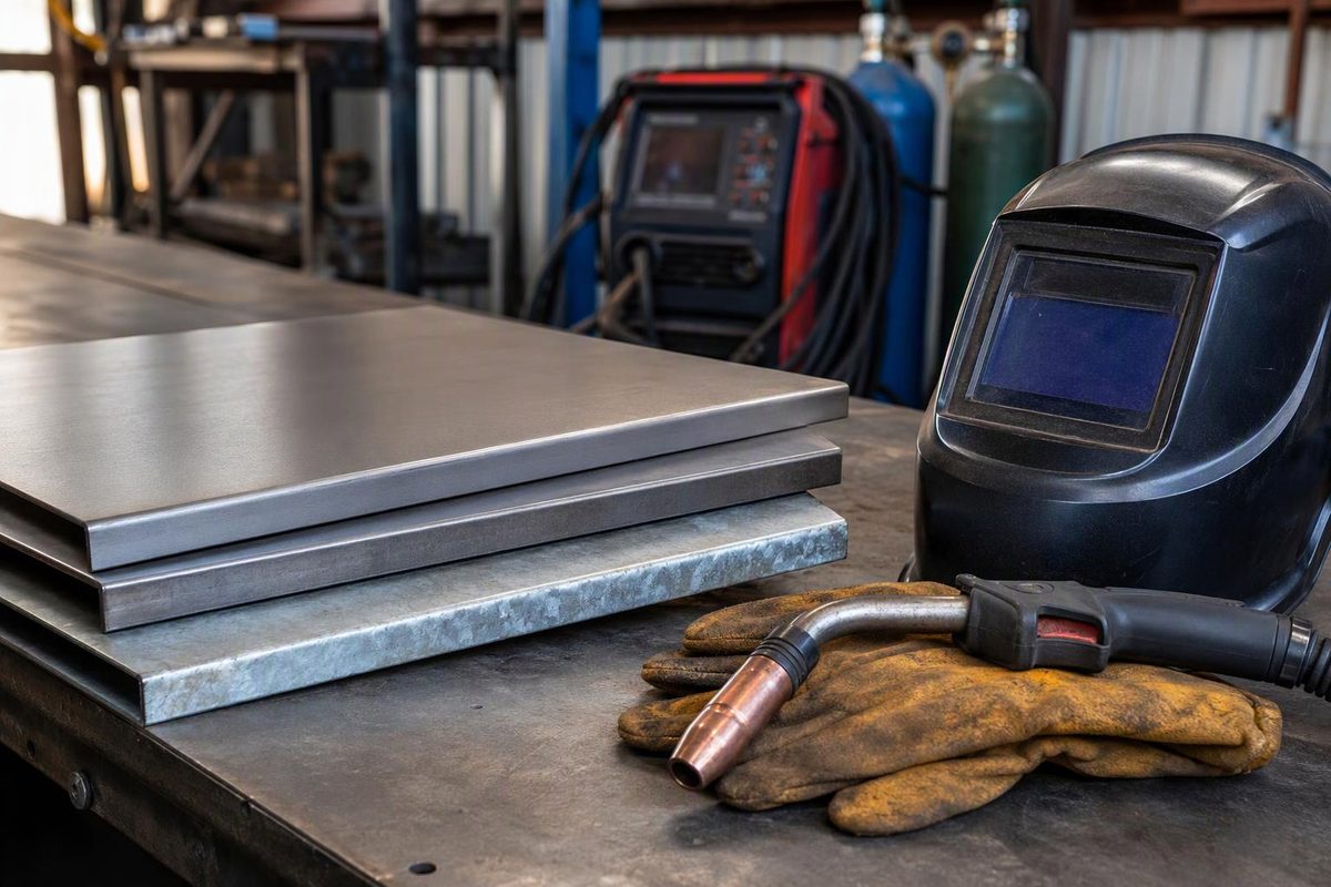
In ordinary U.S. fabrication use, 16 gauge mild steel sheet is nominally 0.0598 inch (1.52 mm) thick. Gauge thickness changes with the metal, and delivered sheet can vary within the applicable tolerance, so critical work should be specified and measured in decimal thickness.
Enter the sheet dimensions and quantity to estimate handling weight for 16 gauge mild steel.
16 Gauge Mild-Steel Weight Estimate
Uses the rounded nominal weight of 2.5 lb/ft² for 0.0598-inch hot-rolled sheet.
Source: Upstate Steel hot-rolled sheet table. This is a handling estimate; delivered thickness, dimensions, alloy and coating can change actual weight.
16 Gauge Thickness Depends on the Material
| Material Sold As 16 Gauge | Nominal Thickness |
|---|---|
| Mild/carbon steel | 0.0598 in (1.518 mm) |
| Galvanized steel | 0.0635 in (1.613 mm) |
| Stainless steel | 0.0625 in (1.588 mm) |
| Aluminum | 0.0508 in (1.291 mm) |
These are material-specific gauge-chart conversions, not interchangeable dimensions. One supplier chart lists all four values and notes that actual thickness varies because of tolerances (Metal Supermarkets). Stock can also be sold at a nearby decimal size: Fabworks, for example, uses 0.0598 inch as the nominal mild-steel conversion but stocks 0.059-inch 1008 sheet (Fabworks).
A separate U.S. statutory “standard gauge” table gives No. 16 as 0.0625 inch. Its operative provision says that table is to be used for determining federal duties and taxes on sheet and plate iron and steel (15 U.S. Code § 206). Commercial mild-steel listings commonly use the 0.0598-inch conversion instead.
For a part that must fit, bend predictably or satisfy a drawing, specify material, grade, finish or coating, decimal thickness and tolerance rather than writing only “16 ga.” Measure unidentified stock with a micrometer, recognizing that paint, galvanizing or another coating affects the reading.
A 16 Gauge Mild-Steel Sheet Weighs About 2.5 Pounds Per Square Foot
A hot-rolled sheet supplier’s table assigns 16 gauge, 0.0598-inch sheet a rounded nominal weight of 2.5 lb/ft² (12.2 kg/m²) and lists these sheet weights (Upstate Steel):
| Sheet Size | Listed Nominal Weight |
|---|---|
| 36 × 96 in | 60 lb |
| 48 × 96 in | 80 lb |
| 48 × 120 in | 100 lb |
| 60 × 120 in | 125 lb |
Use those values for handling and rough estimates, not precision mass calculations. Actual weight changes with sheet dimensions, delivered thickness, alloy and coating.
Gauge Does Not Establish Strength or Bendability
At roughly 1.5 mm, mild steel sheet is commonly used for formed panels, enclosures, guards and light brackets. Gauge alone does not establish whether it is adequate for a loaded part. Stiffness also depends on unsupported span, bends, beads, flanges, section shape and attachment details.
Gauge does not identify strength, chemistry or weldability either. “16 gauge steel” could mean cold-rolled carbon sheet, hot-rolled sheet, stainless steel or coated steel. Confirm the grade and coating before selecting filler metal, bend allowance or a welding procedure.
Bending limits are tooling-specific. One fabricator’s chart identifies its 16 gauge cold-rolled steel as 0.060 inch and offers different inside radii according to the folder or press-brake tooling used (Protocase). A generic “one material thickness” bend-radius rule is preliminary guidance, not a substitute for the brake operator’s tooling table.
MIG Welding 16 Gauge Mild Steel
Short-circuit MIG with small solid wire is a practical process for clean 16 gauge carbon steel because it provides relatively close control of heat on sheet metal. Miller recommends .023- or .024-inch wire for most light-gauge sheet and says .030-inch wire may be usable on 18 gauge and thicker (Miller Electric). The power source’s chart and the wire manufacturer’s data remain the primary starting references.
Use this setup sequence:
- Verify the material and actual thickness. Do not choose a settings-chart row from gauge alone.
- Prepare the joint and return-current path. Remove oil, paint, rust and other contamination as required for the material and procedure. Expose clean metal where the work lead connects and keep the circuit mechanically sound. See why the complete welding return path matters.
- Match wire, gas and polarity. Check the power-source chart and consumable label rather than assuming that solid GMAW wire and self-shielded flux-cored wire use the same polarity.
- Start with the manufacturer’s setting near 0.060 inch. If no chart is available, Miller’s general solid-wire guide uses roughly 1 amp per 0.001 inch of steel, suggesting about 60 A for 0.060-inch sheet. Its rough multipliers convert that to about 210 ipm with 0.023-inch wire or 120 ipm with 0.030-inch wire. Miller presents these as starting calculations and directs the operator to adjust voltage for a stable arc (Miller Electric). They do not override the machine chart, welding procedure or a tested setup.
- Test the complete joint on representative scrap. Match the material, coating condition, joint geometry, orientation and backing. A flat bead on a lap coupon does not prove the same setting will handle a gapped butt joint.
- Control fit-up and accumulated heat. Establish alignment with short, distributed tacks. Where the design permits intermittent welding, stagger short segments to distribute heat. A large root gap needs fit-up correction or an approved backing or joint change—not just a lower setting.
- Change one variable at a time. Burn-through may come from excessive wire feed or current, slow travel, excess gap or repeated heat in one area. Insufficient current can produce a narrow, convex bead with poor toe tie-in; Miller’s parameter guide documents both patterns.
If 0.035-inch wire is already installed, check whether the machine chart covers it at this thickness. Miller’s general range starts .035-inch wire at 50 A, so it can fall within the rough 16 gauge estimate, but smaller wire normally provides a wider low-output working range. Wire classification, polarity, drive-roll groove, liner and contact tip must still agree—use the full .035 wire setup checks rather than changing wire speed alone.
Galvanized 16 Gauge Requires Fume Controls
The galvanized gauge convention lists a different nominal thickness, and the sheet carries a zinc coating. OSHA identifies galvanized steel as a source of zinc oxide fume and zinc exposure as the usual cause of metal fume fever (OSHA).
For covered U.S. workplaces, OSHA’s welding rule directs indoor work on zinc-coated metal to its local-exhaust provisions and confined-space work to its confined-space ventilation provisions (29 CFR 1910.252). Follow the employer’s exposure assessment, coating-removal procedure and ventilation controls; merely keeping your head out of the visible plume is not a complete control plan.
A regular-looking bead does not prove fusion, penetration or structural acceptance. Inspect the joint to the drawing, welding procedure and applicable acceptance criteria, using destructive or nondestructive testing when required. Appearance and weld acceptance are different questions.