
Arc Welding Equipment: Build a Complete, Compatible Setup
Choose arc welding equipment by process, input power, duty cycle and accessory compatibility—then check the circuit before changing weld settings.
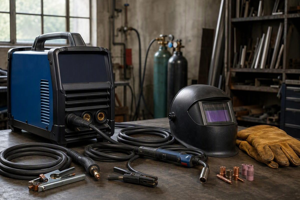
Arc welding equipment is more than the power source. A usable setup also needs a correctly rated electrode holder, gun or torch; a sound welding-current return path; compatible consumables; shielding where required; and protection for the operator and work area.
Stick, MIG, TIG and flux-cored welding all use an electric arc. Choose the process first, then match the entire system—not just the maximum amperage on the box.
Match the equipment to the process
For common manual and semiautomatic work, these are the main equipment combinations:
| Process | Usual power-source output | Equipment beyond the machine and work lead |
|---|---|---|
| Stick: SMAW, also called MMA | Constant current (CC); AC or DC as the electrode requires | Insulated electrode holder and cable, covered electrodes, slag-removal tools |
| TIG: GTAW | CC; DC for common steel work, AC capability for conventional aluminum TIG | Torch, tungsten, compatible torch parts, shielding-gas supply, filler rod when needed; compatible remote current control if used |
| MIG: GMAW | Constant voltage (CV) with a constant-speed feeder | Built-in or separate feeder, gun, matched drive rolls/liner/contact tip, wire, shielding-gas supply |
| Flux-cored: FCAW | Usually CV with a constant-speed feeder | Feeder, suitable gun and feed parts, flux-cored wire, slag-removal tools; external shielding gas for FCAW-G, but not FCAW-S |
Lincoln Electric’s CC/CV explanation establishes the usual output pairing. The Miller Multimatic 235 manual, sections 5 and 11, illustrates connections and supporting equipment; Miller’s TIG guide explains AC/DC selection. Lincoln also distinguishes self-shielded and gas-shielded flux-cored electrodes. These are typical arrangements, not permission to connect arbitrary accessories.
Why CC and CV matter
With stick and TIG, the operator controls arc length by hand. CC output keeps current relatively steady as arc voltage changes. With conventional MIG and flux-cored welding, the feeder supplies wire at a set speed; CV output allows current to respond to changing arc conditions and helps maintain a stable arc length.
A connector adapter cannot turn a CV-only MIG power source into a suitable stick machine. Some field wire feeders can operate from CC sources, but their limitations depend on the process and application. Advanced pulsed systems also do not fit neatly into the conventional CC/CV description. Follow the approved power-source/feeder combination rather than improvising one. Source: Lincoln Electric.
Read the ratings before buying
Start with the base metal, thickness range, joint design, welding position and expected arc-on time. Where a welding procedure specification (WPS) applies, use it to identify required capabilities.
Then check four items in the exact model’s manual:
- Input supply: voltage, phase, frequency and electrical-service requirements. Welding-output amps are not the machine’s input-current requirement. Have a qualified electrician assess the supply rather than selecting a breaker from the front-panel amperage. The Miller manual’s electrical-service and installation guidance, sections 5-2 and 5-3, separates supply ratings from welding output and requires qualified installation.
- Working output range: the current or voltage range needed for the selected consumable and process. Thin TIG work also needs suitable low-current control, not simply a high maximum output.
- Duty cycle at that output: compare ratings at the current and process you will actually use.
- Included versus optional equipment: a TIG torch, remote control, spool gun, gas regulator or electrode-holder lead may be an extra purchase.
Duty cycle is normally expressed over a ten-minute period. A rating of 200 A at 60% duty cycle means six minutes of welding followed by four minutes of cooling at the stated conditions. It does not mean continuous welding at 200 A, nor does it establish the rating at a higher current. Consult the machine’s duty-cycle chart and cooling instructions. Miller’s buying guide explains how output and process affect the rating.
Check what “multiprocess” actually includes
Do not treat “TIG capable” as confirmation of AC TIG, high-frequency starting or foot-pedal support. Verify each feature and the required accessories separately. For example, the Multimatic 235 manual, section 5-12, describes DCEN TIG connections and an optional torch-and-foot-control kit.
For ordinary steel and stainless TIG work, DC capability may be sufficient; for conventional aluminum TIG, choose AC/DC equipment. Aluminum MIG capability is a separate question involving the machine and its supported wire-delivery system. Miller’s TIG equipment guide distinguishes DC steel work from AC aluminum setup.
Match the leads, connections and shielding
Size welding cables for current, duty cycle and total circuit length, using the manufacturer’s cable table. Count both leads: a 50-foot electrode lead plus a 50-foot work lead is a 100-foot circuit. Miller’s cable-sizing guidance in section 5-6 explicitly uses the combined length.
The work clamp completes the welding-current circuit. It is not a substitute for protective grounding of the machine’s frame. Check the clamp contact, cable termination and output connector, not just whether the jaws feel tight. OSHA addresses work-lead attachment and machine-frame grounding separately. Our guide to the welding-current return path explains why a good clamp cannot overcome poor contact elsewhere in a fixture.
For wire welding, match drive rolls, guides, liner and contact tip to wire type and diameter. For TIG, match torch parts and tungsten to the intended setup. Confirm polarity and shielding gas from the consumable data and equipment instructions; do not assume every flux-cored wire uses the same polarity. Lincoln’s flux-cored electrode comparison explains why the two shielding variants need different setups. Use the MIG equipment checklist for a closer look at feeder and gun compatibility.
Include the work area in the equipment budget
Budget for suitable welding eye and face protection, protective clothing and gloves, ventilation or fume extraction, screens for nearby people, and appropriate fire protection. Gas-shielded processes also need a secured cylinder, compatible regulator/flowmeter and sound hoses, as illustrated in the Miller manual’s shielding-gas setup, section 5-13.
In U.S. general industry, OSHA’s welding requirements cover arc protection, clothing, ventilation and fire precautions. Ventilation selection depends on the space, materials and exposure—not merely whether a fan is running. Use the welding safety equipment checklist alongside the machine manual and site rules.
Check equipment before chasing settings
When an arc becomes unstable, use this sequence:
- Stop for defects. Damaged insulation, exposed conductors, wet equipment or overheating connections require correction before further welding. Turn off the unit and disconnect input power before making or tightening connections, following the manual’s shutdown procedures. Equipment repairs belong to qualified personnel.
- Verify mode and polarity. Confirm the selected process and the consumable’s requirements.
- Check the complete weld circuit. Inspect output connections, lead condition and firm work-clamp contact.
- Check delivery and shielding. For wire processes, look for slipping rolls, restrictions and mismatched feed parts. For TIG, check tungsten condition and preparation. Check gas supply, leaks, restrictions and drafts where gas is required.
- Then adjust parameters and technique. Start from the applicable WPS or manufacturer’s guidance for the actual material, consumable, gas, joint and position. Change one variable at a time on representative test material, staying within any applicable procedure limits.
The Miller manual’s troubleshooting sections 8-6 and 10-17 identify cable size, loose connections, polarity, feed restrictions and tungsten condition as possible causes of arc problems. OSHA requires defective equipment to be taken out of use until its safety is assured.
A more stable arc may indicate that a setup fault has been corrected. It does not, by itself, prove fusion, penetration or compliance with the job’s inspection requirements.