
Choose MIG or TIG by the Joint You Need
Compare MIG and TIG for steel, stainless and aluminum. Check speed, heat control, shielding gas and equipment before choosing a process for your next job.
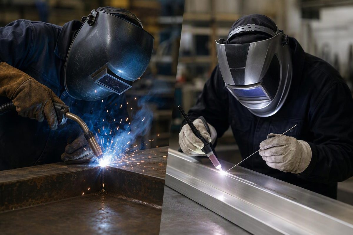
Choose MIG when deposition rate and repeatable production matter most; choose TIG when separate control of heat and filler matters most. In typical semiautomatic MIG versus manual TIG work, continuously fed wire generally makes MIG faster and easier to learn. TIG gives you finer control but requires more coordination between the torch, filler and, often, a remote amperage control. Neither process guarantees a sound joint. Miller’s process comparison explains that control-versus-productivity trade-off.
Start with the alloy, joint access, required weld size and applicable welding procedure—not which bead looks better. Thickness matters, but it does not establish a universal cutoff between the two processes.
Select your material, main priority and shielding conditions to get a process starting point.
Process Starting Point
Starting point—not procedure approval
Start With MIG
Continuous wire feed usually favors repeated mild-steel seams and larger weld volumes over manual TIG.
Setup Check
Match transfer mode, gas, output and joint preparation. Short-circuit MIG can lack fusion or penetration on thicker material.
Follow the specified welding procedure. No universal thickness cutoff or strength ranking is established here.
Sources: article-linked Miller process, TIG, aluminum MIG, rework and shielding-gas guides. Recommendations are qualitative; machine capability and joint details remain unverified.
MIG Trades Separate Filler Control for Continuous Deposition
| Decision Factor | MIG Welding | TIG Welding |
|---|---|---|
| Electrode | Consumable wire | Non-consumable tungsten |
| Filler delivery | Continuous wire feed | Added separately when required |
| Manual productivity | Usually faster | Usually slower |
| Operator coordination | Fewer simultaneous inputs | Torch, filler and current control |
| Delicate joints | Setup-dependent | Fine puddle and filler control |
| Finishing | Spatter varies with setup | Normally little or no spatter |
These are tendencies for common semiautomatic MIG and manual TIG work, not guarantees for every machine or joint. Solid-wire MIG and TIG produce no flux slag; MIG spatter depends strongly on transfer mode and settings.
In gas metal arc welding, or GMAW, the wire is both electrode and filler. Shops commonly call this MIG even when using an active-gas mixture such as argon/CO₂; technically, that is MAG welding. Here, MIG means the common gas-shielded, solid-wire process—not flux-cored welding.
Continuous feeding is the practical advantage: the operator does not stop to introduce individual lengths of filler rod. On repeated seams or joints requiring substantial weld metal, that changes both travel and handling time. The gun still needs consistent positioning, distance and travel speed. Wire feed does not correct poor access or an unsuitable setup.
In TIG—gas tungsten arc welding, or GTAW—the tungsten supplies the arc without intentionally melting into the joint. You can change current without simultaneously feeding more rod. That separation helps when a thin edge needs less heat or a joint needs only a small amount of filler.
Some suitable joints are welded without filler, called autogenous welding. That is an application-specific choice, not permission to omit required weld metal or bridge an unsuitable gap without filler.
A foot pedal is common, not compulsory. Torch-mounted controls can also adjust amperage, and TIG is not limited to flat bench work. Miller’s TIG guide covers remote controls, all-position capability and the equipment distinctions discussed below.
MIG Usually Fits Repeated Mild-Steel Fabrication
For repeated brackets, frames and long seams, MIG is usually the practical starting point. Continuous wire feed makes larger weld volumes less labor-intensive than manual TIG. Where the joint is accessible and the setup is repeatable, TIG’s separate filler control may offer little benefit against the additional operator time.
But “MIG handles thick steel” needs qualification. Short-circuit transfer can produce lack of fusion or penetration on thicker material. A bead deposited over the joint is not evidence that the process fused the required surfaces.
Spray, pulsed MIG and controlled short-circuit processes are not interchangeable settings available on every machine. Match the transfer mode, shielding gas, machine output and joint preparation to the work. Miller’s rework guidance identifies the short-circuit limitation and connects feeding, fit-up and parameter faults to weld defects.
That makes the machine’s actual capabilities more useful than the process name on its front panel. For the supporting setup, see MIG welding equipment compatibility.
TIG Offers Fine Control on Thin Sheet and Stainless
TIG is a strong candidate for short, delicate seams where you need close control of edge melting and filler addition. It lets you manage the puddle without making every change in heat coincide with additional filler delivery.
MIG can still be the better production choice with suitable low-heat transfer, consistent fit-up and equipment matched to the sheet. Thin material alone is not a reason to rule it out. The comparison is between the available setups and the actual joint, not an ideal TIG process against an unsuitable MIG setup.
Finer heat control does not automatically mean less total heat or distortion. Energy per unit length depends on voltage, current and travel speed, with process efficiency also affecting the heat reaching the work. A slow TIG pass can put substantial energy into a small component. TWI’s heat-input explanation explains those variables.
Judge the whole sequence: fit-up, tack placement, weld size, travel speed and accumulated temperature. An amperage display alone cannot tell you which process will distort a particular component less.
For stainless work, gas selection also belongs in the comparison. Do not assume the shielding mixture used for mild-steel MIG suits stainless, or that choosing TIG removes the need for a matched procedure and clean preparation.
Aluminum Requires More Than a MIG or TIG Label
Both processes can weld aluminum. TIG is often attractive for small, detailed work; MIG is attractive when weld volume and speed dominate. The equipment requirements can decide which option is practical before operator preference enters the discussion.
For conventional aluminum TIG, choose AC capability. A DC-only TIG function on a multiprocess machine is not the usual aluminum setup. Steel and stainless commonly use DC electrode negative. Check the actual TIG output capability rather than treating a “TIG-ready” label as an aluminum promise.
Aluminum MIG adds a feeding problem: soft wire can buckle when pushed through a long conventional gun cable. A compatible spool gun shortens that feed path. Miller’s aluminum MIG guide explains the mechanism and equipment selection.
Check compatibility, output and gun duty cycle before buying accessories. Owning a MIG power source does not establish that a particular spool gun will connect to it or that the complete setup suits the required weld volume.
Shielding Gas and Wind Can Override the Process Choice
Pure argon is a common TIG shielding gas. For short-circuit MIG on mild steel, argon/CO₂ mixtures such as 75/25 are common; aluminum MIG commonly uses pure argon. Stainless MIG gas selection depends on transfer mode and machine programming. Miller’s gas-selection guidance covers these distinctions.
Do not substitute a mild-steel MIG argon/CO₂ mixture for TIG gas: CO₂ can promote tungsten oxidation and contaminate the weld. TWI’s shielding-gas comparison explains why. Use the specific MIG gas-selection guide or TIG gas-selection guide, rather than assuming one mixture serves every process.
Both processes depend on external shielding and need protection from drafts. Increasing gas flow is not a reliable wind fix: excessive flow can create turbulence and draw contamination into the shield. Miller’s gas guidance recommends wind protection and warns against excessive flow.
If shielding cannot be maintained, choosing between gas-shielded MIG and TIG does not solve the immediate problem. Establish suitable working conditions before comparing their productivity or finish.
Compare Complete Job Cost, Not Machine Price Alone
MIG’s speed usually favors production economics. TIG’s low-spatter finish can reduce cleanup where appearance matters. Neither observation provides a universal cost winner.
Compare feeding accessories, cylinders, consumables, torch cooling where needed, preparation, arc time, finishing and rework. An existing compatible setup may change the purchase decision, while a recurring production job may make labor time the stronger consideration.
There is no purchase-price comparison or measured productivity ratio in the available sources for the particular machines and joints you might use. A defensible cost decision needs those job-specific figures; assigning a fixed savings percentage to either process would overstate the evidence.
Joint Strength Is Not Decided by the Process Name
There is no useful universal rule that “TIG is stronger.” Required joint performance depends on material, filler, weld dimensions, fusion, defect control and the welding procedure.
The foreword to an AWS standard welding procedure specification explains that procedure qualification provides test data for assessing joint properties. Its application guidance also makes clear that an SWPS does not replace fabrication requirements, appropriate performance qualification tests or engineering judgment. That is guidance about using an SWPS, not blanket approval of either process for every job.
A neat ripple pattern is not proof of root fusion or internal soundness. Visual inspection assesses accessible surfaces; it cannot establish the absence of internal defects. Türk Loydu’s inspection guidance states that limitation.
Structural, pressure and other specified work must follow the applicable procedure and inspection requirements. If the job specifies a process, filler or qualified procedure, a general preference for MIG speed or TIG appearance does not override it.
Diagnose Delivery and Setup Before Switching Processes
A poor result is not automatically evidence that you chose the wrong process. First confirm the alloy, remove contamination safely, and check joint gaps and access. Neither MIG nor TIG makes poor fit-up irrelevant.
Then check filler, shielding gas, polarity and machine mode against the manual and procedure. A mismatch here can defeat otherwise reasonable technique. Manufacturer settings are starting points for the specified material and setup—not universal numbers or qualification evidence.
On MIG, inspect the contact tip, liner, drive rolls and wire feed before chasing settings. Inconsistent delivery makes the arc difficult to stabilize. On TIG, inspect tungsten condition and torch assembly. Check gas connections and the work circuit on both; the work connection is part of the welding circuit, not an afterthought.
Only then adjust parameters and technique. MIG requires coordinated voltage, wire speed, gun distance and travel. TIG requires stable arc length, appropriate current and controlled filler addition. Change one variable at a time on representative practice coupons so that the result tells you something about the adjustment.
The quieter-looking TIG puddle does not remove welding hazards. Both processes require suitable eye, skin and electrical protection, hot-work controls and ventilation. OSHA lists TIG below MIG in typical fume production, but warns that welding gases can displace oxygen and that outdoor work does not guarantee adequate ventilation. OSHA’s welding-fume fact sheet covers those exposure controls. Lower typical fume production is not a reason to omit them.