
Stick Welding Vertical: Control the Puddle Before Changing Amps
Learn vertical-up stick welding setup, rod angle and puddle control, with product-specific amperage examples and fixes for sagging, undercut and slag.
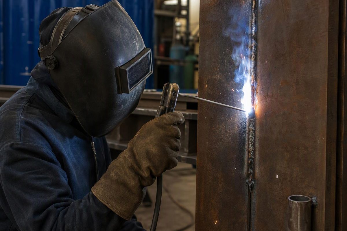
For vertical-up stick welding, start at the bottom, maintain a short arc, and advance with a small, controlled puddle. If a weave is needed, pause briefly at the sides rather than building a large deposit in the middle. A sagging bead is not automatically an amperage problem: excessive deposition, slow travel and a long arc can also make the puddle difficult to control.
The guidance below focuses on E7018 vertical-up practice on carbon-steel plate. An open-root groove, thin sheet or a different electrode needs its own setup; production work must follow the applicable welding procedure specification, or WPS.
Vertical up or vertical down?
Vertical up means welding from bottom to top; vertical down reverses that progression. Lincoln’s introductory guide associates uphill welding with larger welds and downhill welding with fast, shallow welds on sheet metal. That is useful plate-welding guidance—not a rule covering every specialized procedure. Do not reverse travel direction simply because the puddle becomes easier to manage. See the Lincoln learning-to-stick-weld manual, hosted by ManyManuals.
Check the exact electrode’s permitted progression. Lincoln lists its Excalibur and IronArc E7018 products for all positions except vertical down. “All-position” therefore does not mean either direction is acceptable. Lincoln’s E7018 product comparison makes that restriction explicit.
Set the joint and electrode before the amperage
Clean the joint and establish a sound work-clamp connection. Arrange your stance so you can see the leading edge of the puddle and move upward without stretching or letting the electrode angle drift. Miller identifies cleanliness, electrical connection and a clear view as basic requirements for consistent stick welding. Miller’s stick-welding technique guide
Choose rod diameter, polarity and current from the selected product’s instructions and the WPS. Keep low-hydrogen electrodes within their specified storage and exposure requirements; the E7018 rod guide covers that separate setup issue.
For scale, Lincoln’s Australian/New Zealand Excalibur 7018-1MR datasheet publishes these operating ranges:
| Electrode diameter | Published current range | Polarity |
|---|---|---|
| 2.4 mm, approximately 3/32 in. | 70–110 A | DC+ / DCEP |
| 3.2 mm, approximately 1/8 in. | 90–160 A | DC+ / DCEP |
These are product operating ranges, not vertical-up recipes. They do not establish the correct setting for your joint thickness, root opening or pass. Use the instructions supplied with your own rods rather than treating this regional datasheet as universal E7018 data. Lincoln’s Excalibur 7018-1MR datasheet
On a representative practice coupon, adjust current in 5–10 A steps within the permitted range while keeping the other variables steady. Miller recommends those increments and identifies repeated sticking or an arc that extinguishes at the correct arc length as possible low-current symptoms; an excessively fluid puddle can indicate excessive current. Do not keep reducing amps until the bead merely stays in place. Miller’s current-setting guidance
Control angle, arc length and movement
Separate work angle from travel angle. For an equal-leg fillet between plates meeting at 90 degrees, start with the rod centered at roughly 45 degrees between the two surfaces. That distributes the deposit toward both sides. Lincoln’s fillet-joint guidance
For upward travel, use a slight push angle. Miller specifies 0–15 degrees away from the direction of travel for the holder end. Viewed from the side, that means the rod is nearly horizontal, with the holder end slightly below the tip—not steeply tilted upward. Miller’s travel-angle guidance
Maintain a short, consistent arc as the rod burns shorter. Miller gives the electrode’s metal-core diameter as a general starting-point maximum arc length, not a target gap for every rod. Lengthening the arc to see better can increase spatter, undercut and porosity; reposition your head instead. Miller’s arc-length guidance
For the bead itself:
- Establish a small puddle at the bottom. Keep the arc at its leading edge rather than buried in accumulated weld metal.
- Use a straight bead where the joint and procedure allow. A weave is not mandatory.
- If weaving, keep the movement controlled. Pause slightly at each side to allow tie-in, then cross the center without an extra dwell. Do not race across so quickly that the puddle cannot follow.
- Use additional passes instead of an oversized weave. Miller’s general technique guide limits side-to-side movement to twice the electrode-core diameter; follow the WPS’s manipulation and weave limits on production work. Miller’s manipulation guidance
Diagnose the bead in this order
First confirm the electrode, polarity, joint preparation and current range. Then check arc length, movement and travel speed before making another current change.
| Symptom | What to check next |
|---|---|
| Puddle sags or drops | Excessive current, a long arc, slow travel or too much metal deposited per step. Reduce the puddle size rather than repeatedly stopping in its center. |
| Rod sticks or arc stutters | Correct polarity, sound electrical connection and correct arc gap. If those are right, current may be too low. |
| Undercut at the sides | Long arc, excessive current, fast travel or insufficient side pause. Correct the cause before covering the groove with another pass. |
| Heavy, convex bead that appears to sit on the plate | Excessively slow travel can direct heat into the puddle instead of the base metal. Do not assume a bulky bead has good fusion. |
| Slag remaining in grooves between passes | Clean completely and examine bead overlap, toe undercut and sidewall tie-in. More amperage alone is not a cleaning method. |
The current, arc-length and travel-speed relationships above follow Miller’s troubleshooting guidance. TWI explains how inadequate overlap, undercut and uneven preceding passes create pockets that trap slag; a slight dwell at the weave edges assists sidewall fusion. TWI’s slag-inclusion guidance
Clean and inspect before continuing
After each pass, remove all slag by chipping, brushing or grinding as necessary. Check the toes—the boundaries where the weld meets the plate—for undercut, overlap and trapped residue. TWI emphasizes complete slag removal before the next run, including grinding where slag is trapped in crevices. TWI’s interpass-cleaning guidance
Correct defects through the applicable repair procedure rather than burying them beneath the next bead. A tidy ripple pattern does not establish internal fusion or certify the weld; acceptance depends on the specified inspection and testing. The bad-weld diagnosis guide separates visible symptoms from acceptance decisions.
Before striking an arc, provide suitable eye and skin protection, ventilation and fire controls. For vertical work, check where falling sparks and slag can land, including openings and combustible material below the weld. OSHA’s U.S. general-industry welding requirements address these hazards; follow the rules applicable to your workplace and jurisdiction.