
A weld cap completes the specified weld face. Prepare the fill, control both toes, and diagnose undercut, overlap, underfill, slag and porosity.
Learn how to prepare the fill, control cap beads, diagnose common cap-pass problems and inspect the finished weld against job requirements.
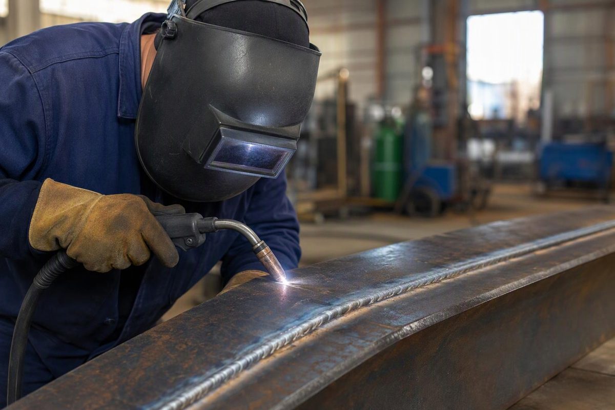
A weld cap, or cap pass, finishes the face of a multipass weld. Its job is to complete the specified weld size and profile while tying into both sides of the joint. It is not merely a decorative layer, and a tall cap does not automatically make a weld stronger.
Strictly, a cap pass is the final pass of a weld joint, as defined in Linde’s welding terminology reference. In shop and field usage, “the cap” may also describe the final layer, which can consist of one bead or several adjacent beads. The arrangement depends on groove width, position, process, filler metal and the welding procedure specification (WPS).
Prepare the weld before capping
Many cap problems begin in the fill layers. Before striking the cap:
- Check the governing requirements. Confirm the WPS process, filler classification and diameter, polarity, position, progression, preheat and interpass limits, permitted technique, parameter range and required final dimensions. A setting copied from another pipe, plate or electrode is not a substitute.
- Bring the fill to the intended level. The surface generally needs to be flush or slightly below flush, with enough of each groove edge visible to guide bead placement. A deep or uneven valley forces the cap to supply too much metal; an overfilled groove leaves nowhere to place the cap without excessive reinforcement. Lincoln Electric gives the same preparation advice in its vertical-down pipeline guide, while emphasizing that the exact procedure depends on the pipe, position and machine (see “Techniques for Welding Fill and Cap Passes”).
- Correct the surface instead of burying it. Remove high spots and feather starts and stops when the procedure permits. Use an approved fill or stripper pass for low areas rather than asking one cap bead to bridge an irregular surface.
- Clean every exposed surface. Remove slag, scale, oxide and loose spatter, paying particular attention to the toes and valleys between beads. Slag can be trapped by undercut, an uneven previous layer or inadequate overlap between adjacent beads. TWI recommends complete inter-run cleaning by suitable grinding, light chipping or wire brushing (slag-inclusion guidance).
Run the cap to the procedure and joint
There is no process-independent “weld cap amperage.” Current, voltage, wire-feed speed and travel speed must suit the process, consumable, material, joint and position—and remain within the applicable WPS range.
For example, Lincoln’s vertical-down SMAW pipeline guide uses lower current for the cap than for the fill. That can help control its stated electrode and final bead, but it is not a rule for vertical-up low-hydrogen electrodes, FCAW, GMAW or GTAW. Start with the WPS and consumable data, then make only permitted adjustments in response to the puddle.
Concentrate on these controls:
- Fill level: Establish it before the cap. The cap should finish the joint rather than rescue an underfilled groove.
- Arc length or voltage: Keep it consistent. An overly wide-spreading arc can melt a groove at a toe without depositing enough metal to refill it.
- Travel speed: Move slowly enough to fill and fuse the edges, but not so slowly that an oversized pool rolls onto unfused base metal.
- Work and travel angles: Keep the arc directed where fusion is needed. On fixed pipe, adjust as gravity’s effect on the pool changes around the joint.
- Edge control: With a procedure-approved weave, dwell only enough at each edge to establish tie-in, then cross the center without piling it high. With stringers, place each bead to remelt the required portion of the preceding bead without forming a slag-catching valley.
- Stops and restarts: Fill the crater, clean the stop and prepare the tie-in as the procedure requires. Do not cover a sharp crater or slag-coated restart with the next bead.
A wide weave is not automatically the right way to cover a wide groove. The WPS, consumable classification, alloy or position may restrict manipulation or favor multiple stringers. See why no welding pattern fits every weld before changing bead width merely to improve appearance.
Diagnose common cap problems
| Visible symptom | Likely mechanism | Check first |
|---|---|---|
| Undercut at one or both toes | The arc melts a groove that the puddle does not refill | Arc length or voltage, current, travel speed, angle and edge dwell |
| Rolled edge or overlap | A large, relatively cold pool flows onto the base metal without fusing | Pool size, travel speed, current, angle and surface scale |
| Cap too high or too convex | Excess deposition for the bead width and travel speed | Pre-cap fill level, deposition rate, travel speed and bead placement |
| Face below the required level | Insufficient deposited metal or excessive travel speed | Remaining groove depth, current or wire feed, and travel speed |
| Valley between cap beads | Poor bead placement or insufficient remelting of the preceding bead | Bead sequence, width and arc placement |
| Slag left at a toe or in a valley | Incomplete cleaning or a pocket formed by undercut or convex beads | Stop, remove the slag and correct the profile before continuing |
| Surface porosity | Gas becomes trapped as the pool solidifies | Contamination, moisture, shielding-gas coverage and arc length where applicable |
| Irregular tie-in or unfilled crater | The restart covered an unprepared stop, or the arc ended without filling the crater | Cleaning, feathering and crater-fill technique permitted by the WPS |
TWI describes excess weld metal as too much filler for the selected travel speed. It associates undercut with factors including an overly wide arc, inadequate fill, excessive speed, high current or poor manipulation, and overlap with a large, cold pool flowing over the surface without fusion (shape-imperfection causes). Change one permitted variable at a time so the result helps identify the cause rather than masking it.
Inspect the cap after cleaning
Remove slag and loose spatter before evaluating the weld face. Check:
- specified face width, location and weld size;
- cap height or reinforcement against the drawing and acceptance criteria;
- transitions at both toes;
- undercut, overlap, underfill, cracks, surface porosity and unfilled craters;
- consistent bead placement and restarts without visible imperfections;
- distortion and joint alignment where relevant.
Do not apply a generic reinforcement limit. Acceptance varies with the governing code or specification, joint geometry, thickness and service. TWI notes that excess cap metal seldom adds useful strength merely by being present, while a sharp toe transition creates a local stress concentration that is particularly important in fatigue service (cap-height discussion).
A smooth cap can still conceal lack of fusion, slag inclusions and other internal discontinuities. Visual examination therefore cannot establish weld soundness by itself. Use the inspection and nondestructive-testing requirements assigned to the job, and compare good versus bad welding by acceptance rather than appearance.
Keep eye protection on while cleaning the cap. OSHA’s eye-protection guidance for shipyard employment says that when slag chips, grinding fragments or wire-brush bristles may fly, the selected protection must cover the sides; a worker using a welding helmet also needs safety glasses with side shields or goggles for those hazards (OSHA fact sheet).