
How Tack Welds Hold Fit-Up Before the Final Weld
Localized welds preserve alignment and joint gap before final welding, then may be removed, completely remelted, or incorporated into the joint.
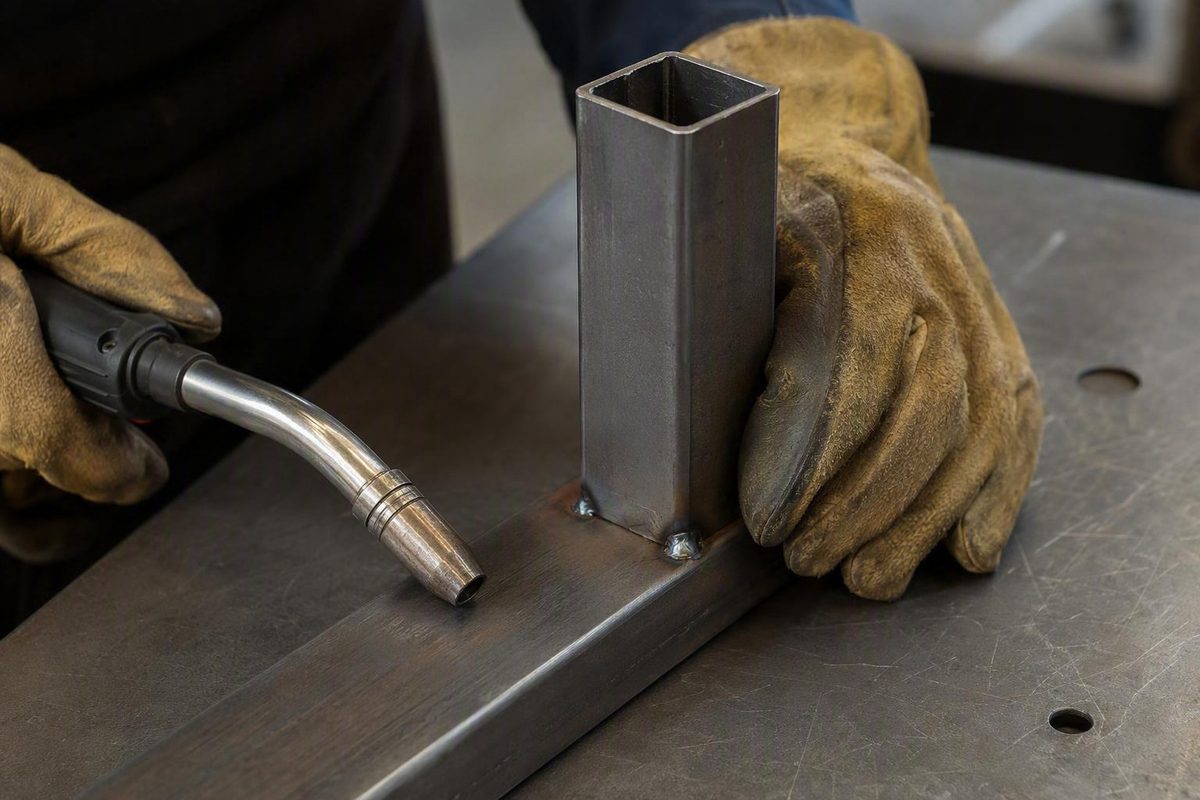
Tack welding means placing localized welds to hold fitted parts in the required position until final welding. The tacks preserve alignment, orientation, rigidity, and joint gap while the assembly is checked and completed. Although their positioning role is temporary, the deposited weld metal may later be removed, completely remelted, or incorporated into the finished joint.
Tack welding defined in plain language
A tack weld acts like a welded fixture. Instead of relying entirely on clamps, magnets, or jigs, the welder places welds at selected locations to keep components from shifting during measurement, handling, and final welding. TWI describes tack welds as temporary welds used to maintain the desired alignment and gap before the finished weld is made (TWI’s tack-welding guide).
Tack welding is a technique, not a separate welding process.
A tack is best identified by its fit-up function, not by a universal maximum length. Most tacks are visibly shorter than the completed weld, but appearance alone does not determine their classification.
Tack-weld definition
- Purpose: Hold components in position and preserve fit-up before or during final welding.
- Typical appearance: Localized beads distributed along or around a joint.
- Final disposition: Removed, completely remelted, or incorporated as permitted by the applicable procedure.
The basic tack-welding workflow
A process-neutral sequence looks like this:
- Clean the joint. Remove contaminants that could interfere with fusion or become trapped in the final weld.
- Fit the components. Establish the required joint gap, root opening, orientation, and alignment.
- Clamp or fixture the assembly. Prevent movement while making the first tacks.
- Place distributed tacks. Choose locations and a sequence suited to the joint and expected shrinkage.
- Recheck the assembly. Confirm dimensions, squareness, angular alignment, joint gap, and orientation.
- Correct the fit-up if needed. Make adjustments before longer welds restrict movement.
- Inspect and prepare the tacks. Clean them and address defects as required.
- Complete the final weld.
Remove clamps only after the tacks adequately stabilize the particular assembly. A few tacks that secure a small bench project may not be sufficient for a long frame, pipe spool, or flexible sheet-metal panel.
An incorrect tack can sometimes be removed and remade, but removal is not automatically harmless. Inspect and restore the affected area under the applicable repair procedure before retacking.
There is no process-neutral amperage, voltage, arc-time, or tack-length setting for every job. These choices depend on the process, material, thickness, joint geometry, position, consumables, and approved procedure.
Why tack welds help control movement and distortion
Clamps establish the initial fit, but they may obstruct access, require repositioning, or be removed before welding is complete. Tack welds preserve fit-up as clamps are adjusted and as final welding applies heat and shrinkage forces.
Weld metal and the surrounding heated material contract as they cool. Uneven contraction can pull a joint out of square, close a gap, change an angle, or warp a panel. Distributed tack placement and a planned sequence can balance restraint and reduce movement, but they cannot eliminate distortion.
Automotive sheet-metal example: A patch panel can be trimmed, clamped, and tacked at several locations around its perimeter. The welder then checks the contour and corrects high or low areas before finish welding. Additional short welds are distributed around the patch, with cooling intervals used to limit heat buildup. Miller’s repair example explains that metal around a weld shrinks as it cools and that thin sheet is particularly prone to warping (Miller’s sheet-metal welding guide).
That sheet-metal sequence is not a universal procedure for pipe, structural steel, pressure equipment or heavy fabrication.
How many tacks are needed—and how far apart?
There is no universal tack size, number, or spacing that works across all welding applications. Collectively, the tacks must maintain the required fit-up during the next operation, but they should not be treated as completed structural welds.
Plan tack placement by considering:
- Joint type and geometry
- Base material and thickness
- Length, width, and rigidity of the assembly
- Welding process and position
- Expected direction and amount of shrinkage
- Access for final welding, cleaning, and inspection
- Clamping and fixturing arrangements
- Forces created by handling or repositioning
- Required root opening and dimensional tolerances
- The applicable welding procedure specification (WPS), drawing, and inspection requirements
Long or flexible work may need more restraint than a compact assembly. A joint welded from one side may require a different sequence from one welded symmetrically. Pipe fit-up must account for root gap, internal alignment, and access around the circumference.
Do not transfer automotive spacing or generic shop ranges into unrelated structural, pipe, bridge, or heavy-fabrication work. A value that works in one example does not establish a safe or code-compliant rule elsewhere.
Nor should a tacked assembly automatically be considered safe to move, rotate, transport, or lift. Evaluate those forces under the project procedure and engineered handling plan before releasing fixtures or moving the work.
Remove, remelt, or incorporate the tack?
“Temporary” describes the tack’s positioning role. It does not necessarily mean the deposited metal must disappear from the finished joint.
| Disposition | When it may apply | Required approach |
|---|---|---|
| Remove the tack | The procedure excludes it, it is misplaced, or it is defective | Use an approved removal method, inspect the base metal, restore the joint preparation, and repair damage as required |
| Completely remelt the tack | The qualified final-welding process is designed to consume it | Meet the WPS conditions for placement, consumables, cleaning, penetration, and remelting |
| Incorporate the tack | The WPS permits it and its quality, profile, and compatibility are acceptable | Clean and inspect it, prepare its ends as required, and blend it soundly into the final weld |
An incorporated tack may require compatible filler metal, specified preheat, suitable cleaning, qualified personnel, and the quality controls established by the current WPS or governing code. Starts and stops may need to be ground or feathered so the final bead transitions smoothly into the tack instead of trapping slag or leaving lack of fusion.
A dated National Board technical article illustrates why pressure-equipment fabrication has historically treated tack welding as a controlled welding operation, including inspection and defect removal before final welding. Because that article was originally published in 1980 and requirements can change, it should not replace the current code or project WPS (National Board guidance on tack welding).
Tack-weld defects that can affect the final weld
A tack may be small, but its defects can become part of a much larger weld. Potential problems include:
- Cracks in the tack or heat-affected zone
- Slag or oxide trapped around the bead
- Porosity or unfilled craters
- Oil, paint, rust, moisture, or other contamination
- Poor fusion to one or both joint faces
- Spatter that obstructs welding or inspection
- A profile that the final bead cannot blend into
- Hard, brittle regions caused by rapid localized heating and cooling in susceptible materials
If an unsound tack is incorporated, inclusions or porosity may remain in the joint. Poor fusion can prevent the final weld from consuming the tack correctly, while cracking can persist or propagate during later passes. Simply covering a defective tack does not reliably repair it.
Before final welding:
- Visually inspect each tack.
- Remove slag, spatter, and surface contamination.
- Look for cracks, craters, porosity, and poor fusion.
- Confirm that the joint gap and alignment remain correct.
- Check that no tack obstructs the root or alters the joint preparation.
- Grind or feather tack ends when required for incorporation.
- Remove or repair unacceptable tacks rather than welding over them.
Exact acceptance limits are application-specific. The current WPS, drawing, governing code, and inspection plan determine whether a tack can remain, requires repair, or must be removed.
Tack welding versus spot welding and other preliminary welds
Weld terminology should reflect what the weld does within the joint—not merely its size or the fact that it was deposited first.
| Term | Primary function | Typical final role | Key distinction |
|---|---|---|---|
| Tack weld | Hold fit-up, alignment, orientation, or joint gap | Removed, remelted, or incorporated | Defined primarily by its positioning function before final welding |
| Resistance spot weld | Join overlapping material using electrical resistance heating and pressure | Normally remains as a permanent joint | A distinct resistance-welding process, not another name for a small tack |
| Root pass | Deposit the first weld pass at the root | Forms part of the completed weld | Being deposited first does not automatically make it a tack |
| Backing weld | Support or facilitate root deposition as specified by the joint design | Serves a defined role in the completed joint | Classified by its design and procedural function |
| Seal weld | Provide sealing for the specified application | Remains where the design requires sealing | Classified by its sealing function, not its place in the sequence |
Resistance spot welding commonly uses dedicated equipment to apply current and pressure through overlapping workpieces. Tack welding can use suitable arc-welding processes and is identified principally by its fit-up role.
A continuous alignment-holding weld presents a terminology question that cannot be settled by length alone. Depending on the joint design and governing requirements, it may be classified as a tack, root pass, backing weld, seal weld, or another specified weld. The WPS, drawings, and applicable standard control that determination.
Safety and code requirements still apply
A short tack presents the normal hazards of welding, including fumes and gases, ultraviolet and infrared radiation, electrical current, hot metal, fire, sparks, and potentially harmful noise. Begin with a task-specific hazard assessment, apply suitable engineering controls such as ventilation or fume extraction, establish required administrative controls, and then select appropriate eye and face protection, clothing, gloves, footwear, hearing protection, and respiratory protection. OSHA presents this control order for U.S. shipyard hot work, so its page should not be treated as the controlling rule for every industry or jurisdiction (OSHA shipyard hot-work guidance).
Coated metals need additional attention. Heating galvanized steel can create hazardous zinc-containing fumes, so the coating, ventilation, respiratory controls, and welding procedure require material-specific evaluation rather than ordinary assumptions (TWI’s material and safety considerations).
For structural steel, pipe, bridges, boilers, pressure equipment, and other regulated fabrication, follow the current WPS, drawings, governing code, inspection requirements, equipment manual, and site rules.
Practical rule: Clean and fit the parts, distribute sound tacks, verify alignment, inspect every tack, and then remove, remelt, or incorporate it only as the applicable procedure and handling plan permit.