
Match Your MIG Welder to the Job and Setup
Compare power, duty cycle and feeding requirements, then check MIG wire, gas, polarity and common faults before changing voltage or wire-feed settings.
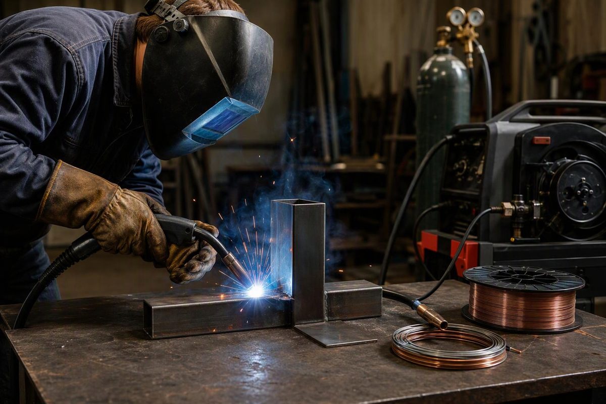
Choose a MIG welder by its operating range for your material and joint, its ratings on your available electrical supply, and its duty cycle at the output you need—not maximum amperage alone. Then match the wire, shielding gas, polarity and feed components. MIG, formally gas metal arc welding (GMAW), feeds a continuous wire electrode through a gun while external gas shields the weld pool; Miller’s mild-steel MIG guide explains how those components work together.
Select your intended welding process to see the setup requirements and what still needs checking.
MIG Setup Path
This identifies a setup path, not a compatible machine or a welding procedure.
Mild Steel: Short-Circuit Starting Setup
| Wire | ER70S-6 solid wire |
|---|---|
| Gas | 75% argon / 25% carbon dioxide |
| Polarity | DCEP: electrode positive, work negative |
| Gas Flow | 20–25 CFH starting guidance |
| Arc Settings | — Not established for your joint |
Checks Before Using This Setup
The gas combination is listed for Hobart BR-6 ER70S-6 wire in short-circuit welding. Miller gives the flow range for mild-steel MIG; it is not universal for every nozzle or application.
Match wire diameter, rolls, liner and contact tip. Confirm the machine's supply requirements and ratings, then use its chart or consumable guidance for thickness, gas and position. Make a representative test joint.
Aluminum: Verify the Feeding System
| Process | MIG with external shielding gas |
|---|---|
| Feed System | Check compatible spool-gun or push-pull options |
| Gas and Wire | — No aluminum specification supplied here |
| Arc Settings | — Use the applicable machine and consumable guidance |
Compatibility and Setup Limits
Soft aluminum wire is more prone to buckling in a conventional push-feed system. Do not assume a spool gun or push-pull gun works with your machine.
The mild-steel gas mix and flow guidance do not establish an aluminum setup. Confirm the alloy, joint, supply requirements, wire, gas and operating range before welding.
Self-Shielded Flux-Cored Is Not MIG
| Process | FCAW-S |
|---|---|
| External Gas | Not required for self-shielded wire |
| Polarity | — Check the specific wire instructions |
| Feed Parts | Match the specific wire and machine |
| Arc Settings | — No wire or joint parameters supplied |
Changeover Requirements
Some MIG machines support this process, but compatibility must be confirmed. Removing gas from solid-wire MIG does not make it self-shielded welding.
Follow the machine's isolation procedure before changing feed components or connections. Check the wire instructions for polarity and parameters.
Sources: Miller's mild-steel MIG, aluminum feeding and first-welder guides; Hobart BR-6 datasheet. Links are in the article. — means not established by the supplied guidance.
Choose a Machine for the Joint, Supply and Workload
Record the alloy, thickness range, joint type and welding position before comparing machines. Sheet-metal work and thick groove welds require different capabilities. Check the manufacturer’s operating range and whether the joint needs preparation or multiple passes. A thickness claim alone is not a welding procedure.
Verify input voltage, phase, circuit requirements and plug arrangement against the exact model’s manual. For a dual-voltage machine, compare its ratings on the supply you will actually use—not just its highest advertised output. The Millermatic 252 manual, revision OM-230 693L, for example, gives electrical-service and input-connection requirements for that machine. Those requirements do not establish what another model needs.
Compare rated output and duty cycle together. A 30% duty cycle at a stated output means three minutes of welding followed by seven minutes of cooling within a ten-minute period, under the specified conditions. Percentages measured at different outputs are not directly equivalent. Miller’s duty-cycle guide explains how to read the chart.
Confirm compatible wire diameters, spool sizes, gun options and shielding-gas equipment. Aluminum also needs a suitable feeding arrangement: soft aluminum wire is more prone to buckling in a conventional push-feed system. A compatible spool gun or push-pull system may be appropriate, but compatibility must be checked, not assumed. Miller’s aluminum feeding guidance describes these alternatives.
Budget for gas, consumables, protection and any electrical installation, not just the power source. No equipment prices or installed-cost figures are supplied here. For a project-based buying comparison, see MIG welders for beginners by project type.
“Gasless MIG” Uses a Different Process
Self-shielded flux-cored arc welding, FCAW-S, supplies shielding through the wire without an external gas cylinder. It is not MIG. Some MIG machines support FCAW-S, but the feeder components and polarity must match the specific wire.
Removing the gas from a solid-wire setup does not convert it to self-shielded welding. Miller’s first-welder guide distinguishes the processes; our gasless wire and setup guide covers the changeover.
Establish the Wire, Gas and Polarity Before Welding
Read the equipment’s safety instructions first. Disconnect input power before servicing feed components or connections, following the manual’s isolation procedures. Before striking an arc, establish suitable ventilation, wear welding PPE and remove or control fire hazards. The Millermatic 252 manual’s safety section details these precautions; use your own equipment’s instructions for its isolation procedure.
For short-circuit MIG welding of ordinary mild steel, ER70S-6 solid wire with 75% argon/25% carbon dioxide is a common starting combination. Hobart’s BR-6 consumable datasheet lists that gas for its ER70S-6 wire and includes short-circuit parameters. This is not a stainless-steel, aluminum or universal transfer-mode setup.
Work through the setup in this order:
- Prepare the joint and work connection. Clean the weld area to bare metal and establish sound metal-to-metal contact at the work clamp. Follow the required joint preparation rather than trying to bridge an unsuitable joint with a larger bead.
- Verify polarity. Conventional solid-wire MIG uses DC electrode positive, DCEP: electrode positive and work negative. Check the machine diagram and consumable instructions, especially after a process change.
- Match the feed path. Fit drive rolls, liner and contact tip suitable for the wire’s material and diameter. Set spool brake and roll pressure by the manual. Too much or too little tension can cause poor feeding.
- Check gas delivery. Confirm the gas, cylinder supply, hose condition and clear nozzle. Miller’s mild-steel guide gives 20–25 cubic feet per hour as a starting flow—not a universal value for every nozzle or application.
- Select starting parameters. Use the machine chart or consumable guidance for the actual wire diameter, gas, thickness and position. Make a test joint representative of the work before proceeding.
Miller’s mild-steel guide covers these preparation, polarity, tension and gas checks. For consumable selection, see choosing solid MIG wire.
Check Feeding and Shielding Before Adjusting the Arc
On a conventional constant-voltage MIG system, wire-feed speed largely determines welding current, while voltage controls arc length. Increasing wire speed generally increases current for the same wire and otherwise comparable conditions. Voltage and wire speed must remain balanced; travel speed and contact-tip-to-work distance also affect the result. Pulsed systems can use different control schemes. Lincoln Electric’s CC/CV explanation describes the conventional relationship.
An automatic setting feature supplies a starting point, not verification of joint quality. Keep technique consistent and change one variable at a time during test welds.
| Symptom | Check Before Changing Settings |
|---|---|
| Uneven feeding or wire tangles | Roll groove and size, spool brake, gun seating, contact tip and liner restriction. Do not simply tighten the rolls. |
| Wire feeds but no arc forms | Work-clamp contact, cable connections and contact tip; then the model’s troubleshooting instructions. |
| Pinholes or visible porosity | Gas supply, leaks, drafts, nozzle blockage and wire or joint contamination. More voltage will not restore missing shielding. |
| Excessive spatter or unstable arc | Polarity, clean wire and metal, steady feeding and connections; then voltage/wire-speed balance and electrode extension. |
These checks follow the general troubleshooting sections of the Millermatic 252 manual, revision OM-230 693L, sections 7 and 9. Use your own model’s manual for fault codes and service procedures. For connection problems, see the complete welding work-current path.
Keep Service Work Safe and Verify Weld Quality
Internal electrical diagnosis belongs with qualified service personnel. Disconnecting power does not necessarily remove stored electrical energy. Use appropriate helmet protection, safety glasses, dry welding gloves, flame-resistant clothing and protection for nearby people, as detailed in the equipment manual’s safety section.
Ventilation remains necessary even when shielding gas protects the weld. OSHA’s welding-fume guidance notes that outdoor welding does not guarantee adequate ventilation, describes local exhaust for removing fumes from the breathing zone, and identifies oxygen-displacement hazards from shielding gases.
A stable arc and tidy bead are diagnostic signs, not proof of complete fusion or certification. Assess welds against the applicable acceptance criteria, welding procedure and required inspection or testing—not appearance alone. The Millermatic 252 manual’s welding guidelines call for test welds that comply with specifications; TWI’s visual-inspection overview explains assessment against specified acceptance criteria.