
How to Read a Weld Bead Without Mistaking Pretty for Sound
Expect consistent size and placement, a controlled profile, smooth toe transitions, and no visible defects—but looks alone cannot prove weld soundness.
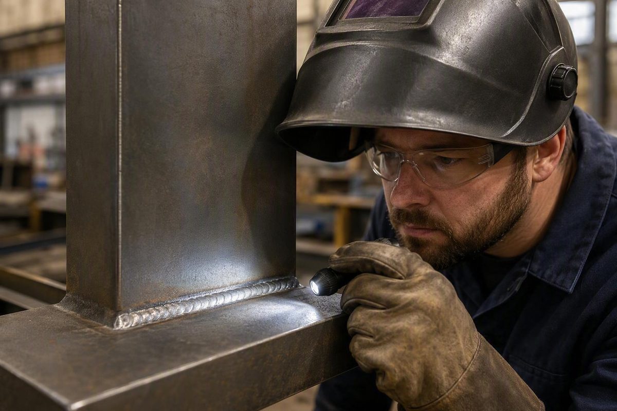
A good weld usually appears straight, consistently sized, and correctly positioned for the joint. Its profile is controlled, and both toes transition smoothly into the base metal. It should show no visible cracks, pinholes, cavities, undercut, overlap, underfill, surface slag, or abrupt changes in width.
That is only the first screen. A smooth bead does not prove fusion, penetration, strength, internal soundness, or compliance. Final acceptance comes from the applicable drawing, welding procedure specification (WPS), project specification, inspection plan, and governing code edition—not from a universal beauty standard (AWS guidance on weld-test preparation and acceptance).
The 30-second visual check
Start with the whole bead rather than its best-looking section. Scan from start to stop and ask:
- Placement: Is the bead centered or otherwise positioned as the joint requires?
- Size: Is its apparent size consistent, and does it match the specified weld?
- Profile: Is the face controlled rather than excessively tall, deeply concave, rope-like, or irregular?
- Toe transition: Does each edge blend smoothly into the adjacent base metal?
- Surface condition: Are there visible cracks, pinholes, cavities, undercut, overlap, underfill, slag, or other discontinuities?
- Starts and stops: Are craters, restarts, and tie-ins filled and blended rather than piled up, narrowed, or left hollow?
Even ripples can suggest steady travel and puddle control, but the “stacked dimes” look is optional. A smooth bead without prominent ripples may be suitable. An evenly rippled bead may still conceal incomplete fusion or penetration. Ripple pattern is not proof of quality.
There is also no universal ideal silhouette. Suitable size and contour depend on the process, joint design, material, welding position, drawing, and procedure. A fillet weld should not be expected to resemble a groove-weld cap, and a profile that is suitable for one application may be excessive in another.
The American Welding Society’s 2008 visual-inspection reference manual treats profile, dimensions, and visible surface discontinuities as inspection subjects while defining quality through conformance to the applicable specification. It is an educational reference, not a substitute for the project’s current code or edition (AWS visual-inspection reference manual).
Bench checklist
- Remove slag, loose spatter, scale, and debris that obstruct the surface.
- Illuminate the entire weld adequately.
- Scan the bead for changes in width, direction, and profile.
- Follow both toes continuously.
- Examine starts, stops, restarts, craters, and tie-ins.
- Measure every dimension identified by the drawing, WPS, or inspection plan.
Visible warning signs and what they mean
A visible discontinuity is a reason to evaluate the weld, not necessarily an automatic rejection. Its significance depends on its type, dimensions, location, and the governing requirements.
| Visible condition | What it looks like | Why it deserves attention | Next step |
|---|---|---|---|
| Undercut | A groove melted into the base metal beside a weld toe | It changes the local profile and may exceed the applicable limit | Measure it with a suitable gauge and compare it with the governing criteria |
| Overlap | Weld metal rolled onto the adjacent surface without a smooth transition | The rolled edge may indicate an unacceptable profile or questionable fusion | Mark its extent and seek disposition under the applicable procedure |
| Visible porosity | Pinholes, pits, or open cavities | It can point to contamination, shielding trouble, or another process problem | Document it, investigate likely causes, and apply the governing criteria |
| Crack | A linear break in the weld, crater, toe, or adjacent base metal | Surface cleanup alone cannot establish that the crack has been removed | Stop and escalate for inspection and authorized disposition |
| Underfill | The finished surface lies below the required joint profile | The weld may not contain the required deposited metal or contour | Measure it against the specified profile |
| Excessive reinforcement or convexity | An unusually high, steep, or bulky bead | The profile may exceed specified dimensions | Measure it rather than judging height by eye |
| Poor toe tie-in | A sharp edge, rolled lip, or abrupt transition | It may indicate poor wetting or fusion at the edge | Inspect both toes closely and escalate if fusion is in question |
| Rope-like or inconsistent bead | A narrow, tall, wandering, or abruptly changing profile | It points to unstable technique or setup and may conceal dimensional problems | Check dimensions before diagnosing the process |
| Visible slag inclusion | Dark or glassy material trapped at a toe or between deposited areas | Slag may remain trapped in or between weld passes | Clean the area, establish the visible extent, and follow the approved disposition |
| Irregular start or stop | A crater, pinhole, lump, narrow tie-in, or unfilled restart | Terminations can concentrate discontinuities | Inspect and measure the complete tie-in area |
| Spatter | Separate droplets deposited around the bead | It may reflect the process or setup but can be external to the weld itself | Remove it where required, then inspect the exposed bead |
AWS visual-inspection material identifies undercut, overlap, porosity, cracks, underfill, slag inclusions, excessive reinforcement or convexity, and irregular profiles as inspection subjects. It also emphasizes measurement and comparison with the applicable criteria rather than acceptance by appearance alone (AWS visual-inspection reference manual).
Treat spatter separately from the deposited weld. Some processes and transfer modes produce more spatter than others. Once removable spatter and slag are cleared, inspect the bead underneath; the absence of a polished finish is not itself grounds for rejection.
A good-looking weld is not automatically a sound weld
Keep three questions separate:
- Does the weld look consistent?
- Is it internally sound?
- Does it satisfy the governing acceptance criteria?
Visual inspection can answer part of the first question and part of the third. It can reveal surface cracks, open porosity, undercut, overlap, underfill, irregular profile, poor placement, and measurable dimensional problems.
It cannot by itself establish tensile strength, complete fusion, full root penetration, or fitness for service. A clean cap can conceal incomplete fusion between weld metal and base metal, incomplete penetration at the root, internal porosity, buried slag, or a crack that does not reach the viewed surface. Smooth-looking toe wetting is encouraging, but it does not prove fusion below the surface.
Formal acceptance requires the job documents. Check the drawing for weld type, location, and size; the WPS for qualified production requirements; the project specification and inspection plan for examination requirements; and the governing code, including its applicable edition, for acceptance criteria. Limits for undercut, porosity, reinforcement, concavity, underfill, and weld size vary among governing requirements (AWS guidance on weld-test preparation and acceptance).
Why good welds do not all look alike
MIG, TIG, stick, and flux-cored welds should not be held to one cosmetic template. Expected appearance changes with:
- Welding process and transfer mode
- Joint design
- Base material and filler metal
- Welding position
- Required weld size and contour
- Surface condition and fit-up
- Service and inspection requirements
A polished or nearly invisible seam is not automatically better. Surface finish and deposited-weld acceptance are separate questions unless the job documents connect them.
Flux-cored arc welding is a useful example. Both self-shielded and gas-shielded FCAW create slag over the completed weld, and that slag must be removed before evaluating the toes, placement, profile, dimensions, undercut, or visible trapped material. Because of the slag and cleanup involved, flux-cored welds may look less cosmetically refined than MIG welds (Miller’s flux-cored welding guide).
Process-aware inspection does not lower the standard. A flux-cored bead still needs the required placement, size, contour, and toe transitions without unacceptable undercut or slag entrapment. It simply should not be rejected because it lacks the finish associated with another process.
Joint type matters just as much. Evaluate a fillet weld against the specified fillet dimensions and contour. Evaluate a groove weld against its required fill, reinforcement, width, and tie-in. Comparing them as though they should share one shape is not useful.
Read the symptom, then check the likely causes
Bead appearance is diagnostic evidence, not a one-to-one fault code. A single symptom can have several causes, and multiple setup or technique problems can occur together.
| Symptom | Plausible causes to check | Practical checks |
|---|---|---|
| Tall or rope-like bead | Puddle too cold, travel too fast, unsuitable work or travel angle, unsuitable stickout | Confirm the procedure, observe the puddle, and verify angles and electrode extension |
| Poor toe wetting | Getting ahead of the puddle, inconsistent travel, unsuitable heat, angle, or wire delivery | Watch whether the puddle reaches both toes and check for stable feeding |
| Uneven width or wandering profile | Inconsistent travel, changing stickout, poor access, unstable arc, feed trouble | Check body position, gun or electrode control, contact components, and work connection |
| Undercut | Poor heat or travel control, unsuitable angles, failure to let the puddle fill at the toes | Inspect both toes, then compare technique and settings with the procedure |
| Visible porosity | Dirty base metal, contaminated filler, inadequate or disturbed shielding, poor fit-up | Clean the joint, inspect shielding where applicable, and check consumables |
| Excessive spatter in wire welding | Unsuitable shielding gas, unstable parameters, feed instability, contact-tip or liner trouble | Verify the specified gas and inspect the feed path and contact components |
| Erratic profile | Intermittent wire feeding, inconsistent arc length, loose connections, changing travel | Observe the arc and verify the setup against the procedure |
| Slag trapped at a toe or between passes | Incomplete cleaning, poor pass placement, restricted joint access, unsuitable technique | Remove slag between passes and preserve access for the following pass |
Manufacturer troubleshooting guidance connects rope-like beads, undercut, poor toe fusion, and inconsistent size with heat, travel, work angle, travel angle, stickout, shielding, and wire-delivery problems. It also identifies liners, contact tips, drive rolls, and drive-roll pressure as possible sources of unstable feeding (Miller’s weld-rework troubleshooting guide).
Keep corrections qualitative until the process and procedure are known. Do not copy a voltage, amperage, wire-feed speed, stickout, or angle from another joint or process. Parameter changes must follow the applicable WPS, filler-metal instructions, equipment manual, material, joint design, and welding position.
Inspect, measure, and escalate before repairing
When a weld looks questionable, use a controlled sequence:
- Identify the requirements. Locate the drawing, WPS, project specification, inspection plan, and governing code edition.
- Clean the surface. Remove slag, loose spatter, scale, and debris without concealing or altering the condition.
- Improve visibility. Use adequate light and a magnifier where appropriate.
- Inspect the complete profile. Follow both toes, then examine the face, starts, stops, craters, and adjacent base metal.
- Measure specified features. Suitable tools may include a machinist’s rule, caliper, undercut gauge, or specialized fillet-weld gauge.
- Document the condition. Record its location, length, orientation, and measured dimensions. Photographs can support the record.
- Obtain the authorized disposition. Accept the weld, escalate it to the responsible inspector or engineer, conduct required testing, or repair it under an approved method.
Additional examination may be required when visual inspection cannot answer the relevant question.
Visual inspection is strongest when planned before, during, and after welding. Before welding, check joint preparation, alignment, fit-up, cleanliness, and accessible root conditions. During welding, monitor pass placement and interpass cleaning. After welding, clean, inspect, and measure the completed joint. This sequence can catch conditions that a finished cap may hide.
Do not automatically cover a suspect area with another bead, grind it smooth, or reweld it. First establish the discontinuity’s extent, determine whether removal is required, identify the applicable repair procedure, and obtain any required authorization. A dated AWS forum discussion illustrates how covering undercut without restoring an acceptable profile can instead create overlap and further repair concerns; the discussion is informal and is not an official code interpretation (AWS forum discussion on undercut repair).
The reliable three-part test is simple: look for consistency and smooth toe transitions, measure what the job requires, and never mistake appearance for proof of internal soundness or formal acceptance. If a discontinuity is visible or the requirements are unclear, document it and consult the current WPS, drawing, code, or authorized inspector before repair or service.