
What to Know Before Buying, Setting Up, or Repairing Miller’s Older 212 MIG Welder
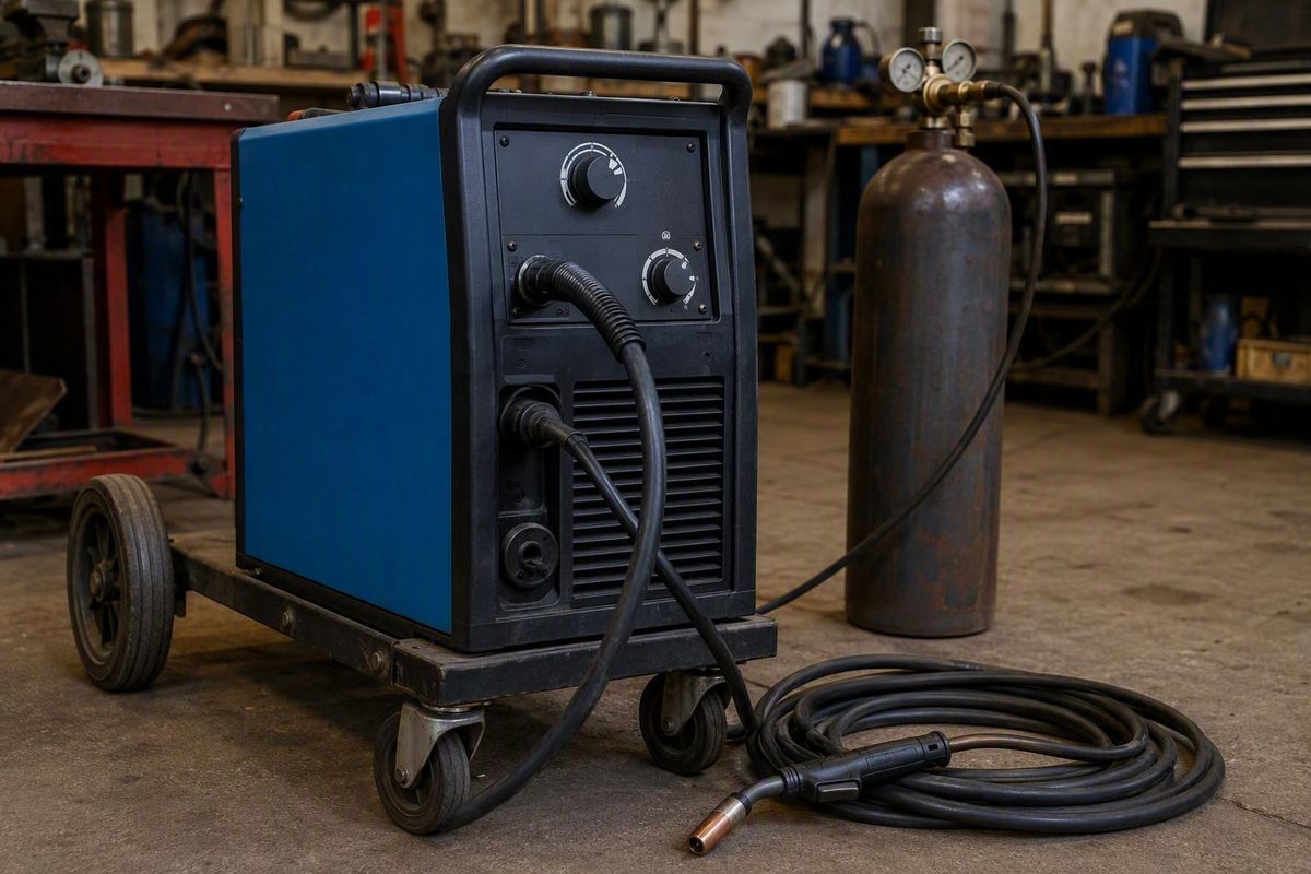
The Millermatic 212 Auto-Set is best evaluated as an older, shop-oriented MIG platform—not simply as a welder with an automatic setting feature. Its historical output, duty cycle, manual controls, and spool-gun options remain attractive, but age introduces questions about package variations, input-power configuration, accessory fit, parts availability, and control-system repair costs.
For a used buyer, the decisive test is not whether the machine powers on or whether the Auto-Set light illuminates. It is whether the exact unit, connected to a suitable supply and equipped with the installed gun, can produce a stable weld under load. For an existing owner, troubleshooting should begin with supply, configuration, wire delivery, polarity, gas, and work-circuit checks before escalating to expensive control components.
This is a historical buying, setup, and symptom-triage guide—not a substitute for an official owner or service manual. The available documentation includes reproduced Miller literature, retailer listings, generic Miller guidance, and owner discussions rather than an authenticated manual matched to every model and serial-number revision. Serial-specific documentation and qualified technical advice should control whenever they are available.
Millermatic 212 Auto-Set at a Glance
The Millermatic 212 Auto-Set is an older all-in-one power source for MIG and flux-cored welding. Historical literature describes it as a 208/230 V, single-phase, 60 Hz machine intended for fabrication, maintenance, repair, farm or home work, and light-industrial applications. Those categories describe its historical market positioning; they do not guarantee that every unit or setup can perform every job within those fields.
One retailer lists model 907405 as sold out and no longer available. The same listing advertised a 22-gauge-through-3/8-inch single-pass range and suggested the Multimatic 235 as a replacement. These are retailer statements, not independent confirmation of official discontinuation, current Miller support, universal thickness capacity, or an exact successor relationship. Review the archived retailer listing for model 907405.
Historical specifications
The following figures come from reproduced historical Miller literature rather than a current manufacturer product page. They help identify the machine’s original class and operating range, but the data plate and a manual matched to the specific model and serial number should govern an individual unit.
| Specification | Historical listing |
|---|---|
| Input power | 208/230 V, single-phase, 60 Hz |
| Rated output | 160 A at 24.5 VDC |
| Duty cycle at rated output | 60% |
| Output range | 30–210 A |
| Wire-feed-speed range | 50–700 IPM |
| Maximum open-circuit voltage | 34.5 V |
| Listed weight | 178 lb |
These figures, along with the historical application categories, appear in a reproduction of the Millermatic 212 Auto-Set brochure.
The 60% duty-cycle rating applies at the stated rated output of 160 A and 24.5 VDC. It does not mean the machine can weld for six minutes out of every ten at every available output setting or under every environmental and installation condition.
Historical literature also describes three supporting features:
- Line-voltage compensation: Intended to maintain more consistent output with approximately ±10% input variation.
- Fan-On-Demand: The cooling system runs when needed rather than continuously.
- Solid-state contactor: The electrode wire remains electrically cold until the gun trigger is pulled.
Line-voltage compensation should not be interpreted as permission to use an improper supply.
Because no authenticated, revision-matched installation manual is available in the supplied documentation, this guide does not prescribe a breaker size, conductor size, receptacle, or plug. Obtain those requirements from documentation matched to the machine’s complete model and serial number and have the installation evaluated by a qualified electrician where necessary.
How the 212’s Knob-Style Auto-Set Works
Auto-Set selects baseline welding parameters from two operator inputs: wire diameter and material thickness. On the Millermatic 212, this is a knob-based system rather than a modern digital interface.
The documented historical sequence is:
- Install a supported solid wire with the corresponding drive roll, liner, and contact tip.
- Connect the specified shielding gas.
- Turn the wire-speed control fully clockwise into the Auto-Set range.
- Select either
.030- or.035-inch wire. - Set the material-thickness control to the workpiece thickness.
- Confirm that the blue Auto-Set indicator is active.
Historical Miller product literature documents this sequence and limits the automatic combination to mild steel, the two supported solid-wire diameters, and C25 shielding gas. C25 commonly denotes a blend of 75% argon and 25% carbon dioxide. Review the historical Millermatic product guide.
Auto-Set compatibility boundary
| Application or setup | Documented knob-style Auto-Set | Manual setup |
|---|---|---|
Mild steel, .030-inch solid wire, C25 gas |
Yes | Optional |
Mild steel, .035-inch solid wire, C25 gas |
Yes | Optional |
| Aluminum | No documented support | Yes |
| Stainless steel | No documented support | Yes |
| Self-shielded or gas-shielded flux-cored wire | No documented support | Yes |
| Alternate shielding gases | No documented support | Yes |
| Other solid-wire diameters | No documented support | Yes |
| Any combination outside the documented steel setup | No | Yes |
That limitation matters when evaluating penetration.
The 212’s controls should not be confused with newer digital systems carrying the Auto-Set Elite name. Owner discussions of later machines may describe fine adjustment around automatically selected settings or a different interface. Those observations do not establish that the 212 has the same adjustment range, control logic, or behavior.
Owner experience is mixed. In a 2019 discussion started by a Millermatic 212 owner, some participants described Auto-Set as useful for reaching a starting point quickly, while the owner and others preferred deliberate manual adjustment. The discussion does not establish a model-wide defect or separate machine behavior from setup, maintenance, material preparation, and technique. Read the 2019 owner discussion about knob-style Auto-Set.
The practical approach is simple: use Auto-Set when the wire, gas, and material fall within the documented combination, then make and inspect a test weld. If the combination is unsupported—or the test does not produce an acceptable result—switch to manual mode and tune the machine deliberately.
Manual Mode, Wire Choice, and Bead-Based Fine-Tuning
Manual mode provides independently adjustable voltage and wire-feed speed. It is also useful when a supported mild-steel setup needs to be tuned for a particular joint, position, preparation, or travel technique.
In a brief 2019 forum discussion, an owner who had used a Millermatic 212 for several years reported that its panel shows marks rather than numerical voltage and wire-feed-speed values. The owner identified that interface as the reason for preferring a different machine. That is an individual workflow and repeatability preference—not evidence that the 212 cannot produce sound welds. See the owner’s description of the control panel.
For recurring work, document:
- Wire classification and manufacturer
- Wire diameter
- Shielding-gas mixture and flow setup
- Material type and thickness
- Joint type and preparation
- Welding position
- Polarity
- Voltage-knob position
- Wire-speed-knob position
- Contact-tip-to-work distance
- Travel angle and approximate travel speed
- Number of passes
- Bead profile and inspection result
A panel photograph may be more repeatable than a note such as “slightly above the third mark.” Keep the photograph with the wire, gas, material, joint, position, and technique information. Knob position alone does not define a complete welding procedure.
Choosing between .030- and .035-inch solid wire
Both documented Auto-Set wire diameters can be useful for general mild-steel work.
In a 2014 discussion about a Millermatic 212 used mainly on approximately 1/16- through 1/4-inch mild steel, many participants favored .030-inch wire for versatility and control. Others preferred .035 inch, particularly where greater deposition on thicker work was useful. These are owner preferences, not controlled performance findings or universal rules. Compare the owner opinions in the Millermatic 212 wire-size discussion.
A practical selection framework is:
- Choose
.030-inch wire when work frequently moves between thinner and moderate material or when lower-end control is important. - Consider
.035-inch wire when the workload is concentrated toward thicker material and greater deposition is useful. - Keep the wire diameter within the appropriate operating range for the intended current.
- Match the drive-roll groove, liner, contact tip, and Auto-Set selector to the actual wire.
- Do not assume that larger wire automatically produces better penetration. Feed stability, voltage, joint design, travel speed, and technique still govern the result.
Building a manual starting point
Miller’s general steel MIG-setting framework treats material thickness as an input for estimating amperage and then matches wire diameter to the intended amperage range. Wire-feed speed strongly influences amperage and penetration, while voltage affects arc length and bead width and height. Miller presents these relationships as starting guidance for steel with solid wire—not as final procedure settings for every machine or joint. See Miller’s general MIG parameter and bead-reading guidance.
When tuning, change one primary variable at a time and observe the result. Large simultaneous changes make it difficult to identify the actual cause.
| Symptom | General starting adjustment | Also inspect |
|---|---|---|
| Arc repeatedly stubs into the work | More voltage may be needed | Excessive wire speed, stickout, work connection, actual material thickness |
| Arc is erratic and wire burns back at the tip | Reduce voltage as a starting response | Restricted feeding, damaged tip, low wire speed, liner condition |
| Bead is tall and narrow | Reassess voltage, travel speed, and feed relationship | Torch angle, joint access, shielding |
| Bead is excessively wide or fluid | Reassess voltage and travel speed | Heat input, fit-up, position |
| Penetration appears weak | Confirm wire speed, voltage, travel speed, joint preparation, and work connection | Supply, polarity, gas, feed slippage |
| Feeding surges | Correct the mechanical feed problem before retuning | Drive-roll pressure, spool drag, liner, tip, gun routing |
The first two responses are general starting points, not universal corrections. Similar symptoms can have different causes.
Every setting—whether selected by Auto-Set, copied from a chart, calculated, or recovered from old notes—must be validated with a test weld. For consequential work, inspect the weld according to the procedure and acceptance criteria appropriate to the application rather than relying on appearance alone.
Material Capacity: What the Thickness Claims Do and Do Not Prove
Historical Miller literature lists 22 gauge as the minimum mild-steel thickness for the Millermatic 212 Auto-Set. That is a material-specific historical figure, not a guarantee that every operator can weld every 22-gauge joint without distortion or burn-through.
The retailer’s archived listing advertised a 22-gauge-through-3/8-inch single-pass range, but the upper figure lacks enough conditions to function as a universal rating. It does not fully define:
- Base-metal type or alloy
- Joint type and preparation
- Welding position
- Root opening
- Wire classification and diameter
- Shielding gas
- Transfer behavior
- Travel technique
- Required penetration
- Acceptance criteria
- Input-power conditions
Most importantly, the available evidence does not support interpreting the 3/8-inch claim as one-pass capacity on 3/8-inch aluminum.
Practical thickness capacity depends on the complete welding system. A prepared groove creates a different demand than an unprepared square butt joint. A flat-position fillet is not equivalent to an out-of-position weld. Root opening, bevel angle, cleanliness, gas, wire, polarity, travel speed, contact-tip-to-work distance, duty cycle, and pass count all matter. Where preheat is appropriate, it should be specified by the material and application procedure rather than used casually to force the machine beyond a documented process.
Multiple passes also change the question. “Can this machine weld the material?” is incomplete unless the seller or operator specifies whether that means a single-pass joint, multipass groove, fillet weld, or merely a bead deposited on the surface.
A 2009 forum case illustrates the variables that should be investigated when aluminum penetration appears weak. The owner reported using .035-inch wire, a Spoolmatic 30A, and 100% argon, and suspected an input-power problem. Participants suggested checking measured line voltage, circuit capacity, cable-run voltage loss, plug wiring, supply phase, and the machine’s input-jumper configuration. The discussion did not document a final diagnosis or repair. Review the unresolved weak-output aluminum discussion.
One participant offered an estimate of realistic aluminum capacity, but that opinion should not be treated as a Miller rating. The result would depend on alloy, joint geometry, preparation, spool-gun setup, wire, argon flow, position, available input power, and required weld quality.
For a used purchase, require a demonstration under conditions reasonably close to the intended work. If the goal is aluminum fabrication, test the actual alloy and thickness with the included spool gun, suitable wire, appropriate shielding gas, and the supply that will be available. If the goal is thicker steel, test a representative joint rather than accepting a surface bead as proof of penetration.
Guns, Spool Guns, Consumables, and Package Variations
Not every Millermatic 212 was necessarily sold with the same gun or accessory package. Reproduced older Miller literature lists a 15-foot M-25 MIG gun. That historical package description should not be assumed to identify the gun currently installed on a used machine.
A retailer describes model 907405 as including a later 15-foot, 250 A MDX 250 gun. This package difference matters because the correct tips, nozzles, liners, and related components depend on the gun actually fitted to the machine. See the retailer’s package description.
Before ordering parts, identify what is physically installed. Do not assume the power source’s front-panel model determines its gun consumables.
Record:
- The power-source model and serial number.
- The complete gun model shown on its label or handle.
- The rear connector and trigger-plug arrangement.
- The liner type and length.
- The contact-tip, nozzle, and related consumable family.
- Any adapter between the gun and power source.
Historical literature references the Spoolmate 200 and Spoolmatic 15A/30A as spool-gun options for the 212. It describes Gun-On-Demand as the ability to select between connected guns by pulling the trigger on the desired gun.
The historical Spoolmate 200 listing covers .030–.035-inch aluminum wire and .023–.035-inch steel or stainless wire. Those figures describe the gun’s historical wire range, not universal connection compatibility with every 212 revision. Verify the power-source serial number, gun connector, control arrangement, trigger wiring, speed control, and any required adapter before purchasing.
A distributor lists part MI1770037 as a 15-foot, 250 A, air-cooled gun for .030–.035-inch wire using AccuLock MDX consumables and includes the Millermatic 212 in its compressed compatibility list. Treat it as an option to investigate—not as proof of direct fit across every production revision. Check the distributor’s MI1770037 description.
Accessory-verification checklist
Before buying a gun, spool gun, or complete used machine, verify:
- Power-source identity: Exact model and serial number
- Primary gun: Model, cable length, rear connector, and trigger plug
- Consumable system: Tip, diffuser, nozzle, and retaining components
- Liner: Correct material, length, and wire-size range
- Drive rolls: Correct groove style and diameter range
- Wire: Classification, material, and diameter
- Polarity: Correct for the selected wire and process
- Spool-gun connection: Weld-current connector, trigger/control plug, and speed control
- Spool-gun support: Serial-specific confirmation of compatible controls
- Gas equipment: Suitable regulator or flow gauge, hose, and shielding gas
- Work circuit: Work lead, clamp, connector, and cable condition
- Running gear: Cart, cylinder rack, chains, axle, wheels, and hardware
- Other parts: Power cord, plug, thickness gauge, manuals, spare tips, and adapters
A cheap bare power source can become an expensive project after adding the correct gun, regulator, work lead, drive rolls, running gear, and spool-gun equipment. Price the welder as a complete operating system rather than as a cabinet with a power switch.
Used Millermatic 212 Inspection Checklist
Begin with identity and completeness before applying power.
1. Inspect the machine and package
Check the:
- Data plate
- Model and serial numbers
- Cabinet condition
- Signs of impact, corrosion, heat, or water exposure
- Power cord and plug
- Work lead and clamp
- Installed MIG gun
- Regulator or flow gauge and hose
- Running gear and cylinder restraint
- Drive rolls
- Spool hub and brake components
- Included spool gun, adapters, and controls
- Loose parts or undocumented modifications
Open only access doors intended for routine wire setup. Do not remove covers simply to conduct an informal energized inspection. A disconnected visual inspection by a competent person may reveal debris, damaged connectors, or modifications, but internal electrical diagnosis is a different task.
2. Confirm input configuration
Verify that the input-voltage jumper is configured for the actual supply. The permitted input range and exact configuration method should come from documentation matched to the model and serial number.
An unqualified buyer should not alter internal wiring or inspect energized components. Ask the seller to have the configuration confirmed before the test, or arrange for a qualified electrician or welding-equipment technician to do it.
Do not assume that an existing plug proves correct configuration. A plug may have been replaced without changing the internal jumper, and receptacle shape alone does not establish measured voltage or available circuit performance.
3. Test basic operation
With a suitable supply and safe setup, check:
- Normal startup
- Power-switch operation
- Indicator behavior
- Voltage- and wire-speed-control movement
- Gun-trigger response
- Contactor operation
- Stable wire feeding
- Gas-solenoid operation and gas flow
- Work-clamp condition
- Auto-Set engagement and blue indicator
- Manual-mode response
- Primary MIG gun operation
- Spool-gun operation, if included
- Gun-On-Demand selection, if configured
Because the machine has Fan-On-Demand, a fan that does not run continuously does not by itself prove a fault. Interpret fan behavior alongside trigger response, contactor operation, wire feed, output, indicator lights, temperature, and the loaded weld test.
4. Require a loaded weld test
A machine that powers on or feeds wire has not demonstrated that it welds correctly. Test it on clean material using known wire, suitable shielding gas, correct polarity, and a sound work connection.
Ideally, test both:
- A moderate setting that makes arc stability easy to assess
- A setting closer to the intended workload, without exceeding documented operating or duty-cycle limits
During the weld, watch and listen for:
- Stable or surging wire feed
- Repeated burnback
- Erratic arc output
- Unusually weak penetration
- Abnormal indicator lights
- Intermittent contactor behavior
- Overheating or unexpected shutdown
- Excessive heat at plugs, connectors, leads, or work-cable joints
- Gas leakage or unstable coverage
- Delayed or inconsistent trigger response
If a spool gun is included, test it with the appropriate wire and gas. A seller’s statement that it “worked last time” is not equivalent to a present demonstration.
5. Document the test conditions
Write down or photograph:
- Available supply and circuit description
- Line voltage confirmed through a qualified check
- Input-jumper configuration
- Wire classification and diameter
- Shielding gas
- Material and joint
- Knob positions
- Gun used
- Bead result
- Any indicator or shutdown sequence
This record helps separate machine behavior from setup problems and is especially valuable if the unit later goes to a repair shop.
Treat absent accessories as real replacement costs. Guns, regulators, work leads, carts, cylinder racks, spool guns, adapters, and consumables can materially change the total purchase. Historical retailer prices do not establish current used value, which varies with condition, region, accessories, demonstrated operation, and repair risk.
Troubleshooting Weak Output, Shutdowns, and Dead Wire Feed
Troubleshoot by symptom and risk level. Begin with external causes that can be checked safely; do not jump from unusual behavior directly to a main-board diagnosis.
Weak output or poor penetration
Start with the complete supply and welding circuit:
- Confirm that actual supply voltage is within the machine’s permitted configuration.
- Confirm that the input-voltage jumper matches the supply.
- Have circuit capacity and voltage drop checked where weak input power is suspected.
- Inspect the plug and power cord for damage, overheating, or loose connections.
- Verify polarity for the installed wire and process.
- Attach the work clamp to clean, bare metal near the weld.
- Inspect the work lead, clamp, and machine connection.
- Confirm the shielding gas and flow.
- Verify wire classification and diameter.
- Check drive-roll selection, pressure, liner condition, contact-tip size, spool drag, and gun routing.
- Clean and prepare the joint.
- Make a controlled test weld using documented settings and consistent technique.
The historical ±10% line-voltage-compensation feature may reduce output variation within its intended range. It cannot correct improper wiring, an unsuitable supply, excessive voltage drop, a damaged connection, or the wrong jumper configuration.
The work circuit can also imitate a power-source problem. Look for burned jaws, loose cable attachment, corrosion, unsuitable replacement parts, or a clamp attached over paint or heavy scale. Resolve an obvious work-circuit fault before condemning the power source.
Startup followed by an immediate shutdown
In a 2025 forum report, an owner described a sequence in which the contactor engaged, the blue and overtemperature lights illuminated, and the machine shut down about one second later. Participants suggested checking the power switch, wiring, input configuration, thermal-sensor circuit, front-panel board, and main board. Testing with a reported 230 V supply did not resolve the symptom, and the discussion ended without a confirmed diagnosis. See the unresolved one-second shutdown report.
That case supports a diagnostic list, not a replacement-parts conclusion. An overtemperature indication at startup may direct a technician toward the thermal circuit, but it does not identify the failed component.
For a similar symptom:
- Record the exact light, contactor, and shutdown sequence.
- Confirm supply and jumper configuration.
- With the machine disconnected, look for visibly damaged external wiring or connectors.
- Confirm that recently replaced parts match the model and serial-number revision.
- Discontinue repeated cycling if the machine continues behaving abnormally.
- Have the switch, thermal circuit, front-panel controls, and main board tested using appropriate service information.
Transformer hum with no fan, feed, or response
In another owner report, the transformer hummed while the fan, wire feed, and other normal functions remained inactive. The owner said the power switch, cord, gun, connections, jumper configuration, and trigger continuity had been checked. A later update stated that Miller had identified a board fault, but the thread supplied no diagnostic record and did not confirm that replacement or repair restored operation. Read the transformer-hum and reported board-diagnosis discussion.
The owner also reported measuring 53 V at the board. That number should not be treated as a valid specification or diagnostic threshold. Without an official schematic, identified test points, measurement conditions, expected waveform, meter requirements, and revision-specific service values, it does not prove that the supply or board is good or bad.
Before assuming a board failure, safely rule out external and mechanical causes such as:
- Damaged gun trigger or control lead
- Open trigger circuit
- Incorrect or loose gun connector
- Drive-roll slippage
- Wrong drive-roll groove
- Excessive spool tension
- Blocked, damaged, or incorrect liner
- Damaged contact tip
- Poor work connection
- Incorrect input-jumper configuration
- Visible loose, burned, or damaged connections while the machine is disconnected
- Recent modifications or mismatched replacement parts
These checks cannot eliminate every board fault, but they may prevent an expensive component from being ordered for a problem elsewhere in the system.
Safety boundary
Do not use this guide as a board-level repair procedure. Internal energized measurements, rewiring, thermal-sensor testing, contactor testing, and circuit-board diagnosis should be performed by a qualified welding-equipment technician using revision-matched service information.
Use appropriate welding PPE and ventilation, control fumes and ultraviolet exposure, and follow the equipment manual and site rules. As an editorial safety policy, Welder Facts states that equipment-specific instructions and site requirements override its general articles. Review the site’s safety and informational-use notice.
Is a Millermatic 212 Worth Buying or Repairing?
A working Millermatic 212 can still be useful, but its value depends more on verified operating condition and package completeness than on the Auto-Set badge.
Practical strengths
Historically, the machine offered:
- Rated output at a 60% duty cycle
- Automatic and manual operating modes
- Continuously adjustable manual voltage and wire feed
- Spool-gun options
- Gun-On-Demand capability in supported configurations
- Running-gear packages
- A conventional shop-oriented all-in-one format
- Fan-On-Demand cooling
- Line-voltage compensation
That combination can suit a shop that wants a dedicated MIG machine and does not require lightweight portability or a digital interface.
Important tradeoffs
The drawbacks become more consequential as the machine ages:
- Its historical listed weight is 178 lb.
- One owner reported marks rather than numerical voltage and wire-speed readouts.
- Documented Auto-Set use is limited to mild steel,
.030- or.035-inch solid wire, and C25 gas. - Guns and consumable systems can vary by package or later modification.
- Current factory support and critical-parts availability are unresolved.
- Board or control faults may create significant financial exposure.
- A seller may not know whether the input jumper, replacement gun, or internal parts match the machine.
- Repair downtime may exceed the time needed to obtain a better-supported alternative.
In February 2026, one owner reported estimated board-replacement costs of approximately $600–$1,000 and repair estimates of about $400 or more. These are anecdotal, time-sensitive figures, and the report did not document a completed successful repair. Actual cost can vary with board revision, supplier, core requirements, repair service, shipping, labor, and warranty. See the dated owner report and cost estimates.
Calculate the total exposure
Compare more than the asking price:
- Purchase price
- Diagnostic labor
- Electrical-installation needs
- Missing primary gun
- Missing regulator and hose
- Missing work lead or damaged clamp
- Drive rolls and consumables
- Running gear
- Spool gun and adapters
- Board repair or replacement
- Other unavailable parts
- Transportation or shipping
- Expected downtime
- Warranty on repair work
- Resale value after repair
- Price and support of an alternative machine
A low purchase price may justify diagnostic risk for a buyer who can source parts and tolerate downtime. It is less attractive for a production shop that needs predictable service.
Decision matrix
| Situation | Recommended decision |
|---|---|
| Machine passes a loaded weld test in the relevant modes, accessories are complete, and price reflects age | Buy |
| Machine welds properly in manual mode but Auto-Set is inconsistent, and manual operation meets the intended need | Consider buying at an adjusted price |
| Fault has been professionally identified, the exact part is available, and total cost is justified | Repair |
| Machine needs a known, inexpensive external component and otherwise passes inspection | Repair may be reasonable |
| Seller permits only a power-on or wire-feed demonstration | Treat as unproven or nonworking |
| Diagnosis is uncertain and an expensive board is merely suspected | Pause or walk away |
| Critical parts or serial-specific compatibility cannot be verified | Walk away or replace |
| Purchase, accessories, diagnosis, repair, and downtime approach the cost of a better-supported alternative | Replace |
| Intended work depends on an unverified 3/8-inch or aluminum-capacity claim | Require a representative weld test |
One retailer suggests the Multimatic 235 as a replacement, but that sales recommendation does not establish an exact successor relationship. Compare any alternative according to the process, output, duty cycle, gun configuration, input power, aluminum workflow, service support, and portability the work actually requires.
Before deciding, verify:
- Current Miller support for the complete model and serial number
- Serial-specific control-board and superseded part numbers
- Availability of the correct owner and service manuals
- Replacement-gun connector and trigger compatibility
- Consumable family for the installed gun
- Spool-gun controls and required adapters
- Local welding-equipment repair capability
- Diagnostic fees and repair warranty
- Availability and lead time for critical electrical parts
Frequently Asked Questions
Is the Millermatic 212 Auto-Set discontinued?
A retailer lists model 907405 as sold out and no longer available, while the supplied Miller literature describes an older product line.
It does not independently establish an official manufacturer discontinuation date or the present availability of every factory part, manual, or repair service. Verify current support directly with Miller or an authorized service provider using the complete serial number.
Can the Millermatic 212 Auto-Set weld aluminum automatically?
The supplied historical documentation does not support Auto-Set operation for aluminum. Its documented automatic combination is mild steel with .030- or .035-inch solid wire and C25 shielding gas.
The machine was historically offered with aluminum-capable spool-gun options, but aluminum should be set up in manual mode using a verified compatible gun, appropriate aluminum wire, suitable shielding gas, correct polarity, and settings validated by a test weld.
Does the Millermatic 212 display numerical voltage and wire-feed speed?
According to one longtime owner, the front panel uses marks rather than numerical voltage and wire-feed-speed readouts. That may make exact setting transfer less convenient, but it does not inherently determine weld quality.
For repeat work, record or photograph knob positions along with the wire, gas, material, joint, position, and technique. A panel photograph without the rest of the setup is incomplete.
Can the Millermatic 212 weld 3/8-inch material in one pass?
A retailer advertised a single-pass range extending to 3/8 inch, but the claim does not supply enough conditions to apply to every material, alloy, joint, position, wire, gas, or acceptance requirement. It should not be interpreted as evidence of one-pass capacity on 3/8-inch aluminum.
Require a representative test using the intended material, preparation, position, power supply, wire, gas, and technique. Distinguish a completed single-pass joint from a surface bead or multipass weld.
Does no wire feed or an immediate shutdown mean the control board has failed?
No. A failed board is one possibility, but these symptoms can also involve input configuration, the power switch, trigger circuit, wiring, thermal-sensor circuit, front-panel controls, connectors, or other components.
The cited owner reports do not establish one universal cause. One immediate-shutdown case ended without a confirmed diagnosis. Another owner later reported being told that a board was faulty, but provided neither a service record nor confirmation of a successful repair. Rule out safe external causes and obtain a serial-specific diagnosis from a qualified welding-equipment technician before ordering an expensive board.
The Millermatic 212 Auto-Set should ultimately be judged as an older shop-class MIG welder rather than by Auto-Set alone. A sound unit may remain useful because of its historical output, duty cycle, manual controls, and spool-gun options. Buyers should identify the exact configuration, test it under load, and account for missing accessories and repair uncertainty. Owners facing electrical or control symptoms should check safe external causes first and obtain a professional, serial-specific diagnosis before purchasing an expensive board or assuming replacement is necessary.